Vaillant auroCOMPACT VSC S/4 Series User manual

Installation and maintenance instructions
auroCOMPACT
VSC S ../4
AT, DE
Publisher/manufacturer
Vaillant GmbH
Berghauser Str. 40 D-42859 Remscheid
Tel. +49 21 91 18‑0 Fax +49 21 91 18‑2810
[email protected] www.vaillant.de

Contents
2Installation and maintenance instructions auroCOMPACT 0020181589_04
Contents
1 Safety.................................................................... 4
1.1 Action-related warnings ......................................... 4
1.2 Intended use.......................................................... 4
1.3 General safety information .................................... 4
1.4 Regulations (directives, laws, standards).............. 6
2 Notes on the documentation .............................. 7
2.1 Observing other applicable documents ................. 7
2.2 Storing documents................................................. 7
2.3 Validity of the instructions...................................... 7
3 Product description............................................. 7
3.1 Serial number ........................................................ 7
3.2 Information on the identification plate.................... 7
3.3 CE label ................................................................. 7
3.4 ÖVGW symbol....................................................... 7
3.5 DVGW mark........................................................... 8
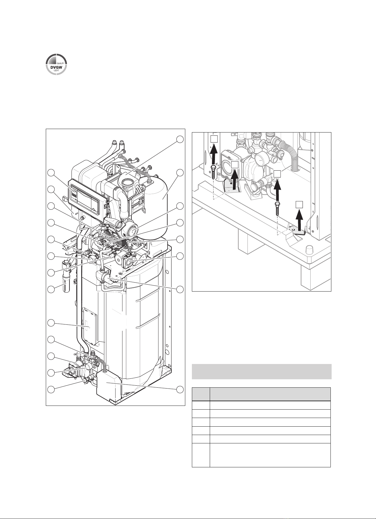
3.6 Functional elements............................................... 8
4 Set-up.................................................................... 8
4.1 Unpacking the product........................................... 8
4.2 Checking the scope of delivery.............................. 8
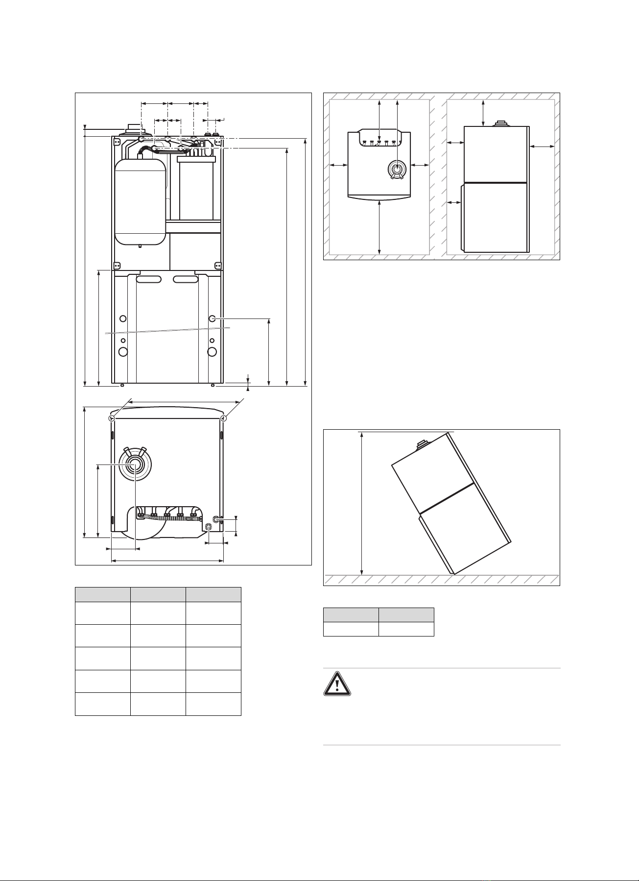
4.3 Unit dimensions ..................................................... 9
4.4 Minimum clearances.............................................. 9
4.5 Clearance from combustible components ............. 9
4.6 Unit dimensions for transport................................. 9
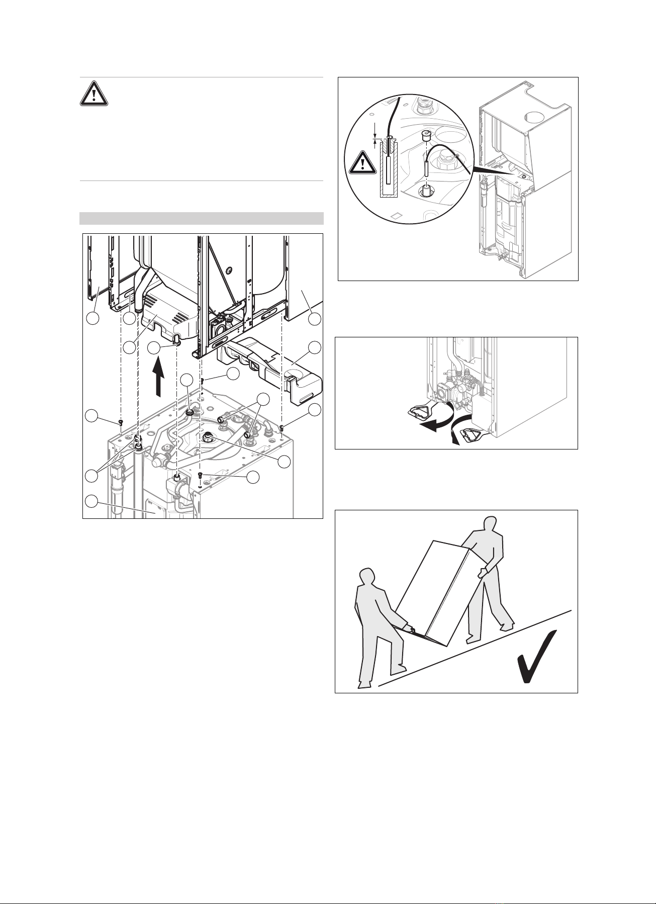
4.7 Transporting the unit.............................................. 9
4.8 Unit installation site.............................................. 11
4.9 Setting up the unit horizontally ............................ 11
4.10 Removing/installing the front casing.................... 11
4.11 Installing/removing the side casing...................... 11
4.12 Moving the electronics box into the lower or
upper position ...................................................... 11
4.13 Removing/installing the vacuum chamber's
front wall .............................................................. 12
5 Installation.......................................................... 12
5.1 Information on liquid gas operation ..................... 12
5.2 Checking the gas meter....................................... 13
5.3 Gas and water connections ................................. 13
5.4 Connecting the condensate drain pipework ........ 13
5.5 Solar connection.................................................. 14
5.6 Air/flue system ..................................................... 15
5.7 Electrical installation ............................................ 16
6 Operation............................................................ 19
6.1 Operating concept of the product ........................ 19
6.2 Live Monitor (status codes) ................................. 19
6.3 Test programmes................................................. 19
7 Start-up............................................................... 19
7.1 Auxiliary service equipment................................. 19
7.2 Checking the factory setting ................................ 20
7.3 Filling the condensate siphon .............................. 20
7.4 Filling the solar system ........................................ 21
7.5 Switching on the product ..................................... 22
7.6 Running the installation assistants ...................... 22
7.7 Restarting the installation assistants ................... 23
7.8 Calling up appliance config. and diagnostics
menu.................................................................... 23
7.9 Performing a gas family check ............................ 23
7.10 Using check programmes.................................... 24
7.11 Checking and treating the heating water/filling
and supplementary water .................................... 25
7.12 Reading off the filling pressure ............................ 26
7.13 Preventing low water pressure ............................ 26
7.14 Filling and purging the heating installation .......... 26
7.15 Filling and purging the hot water system ............. 26
7.16 Checking and adjusting the gas settings............. 27
7.17 Checking leak-tightness ...................................... 28
8 Adapting the unit to the heating
installation.......................................................... 28
8.1 Calling up diagnostics codes ............................... 28
8.2 Setting the maximum heating output ................... 29
8.3 Setting the pump overrun and pump operating
mode.................................................................... 29
8.4 Setting the maximum flow temperature ............... 29
8.5 Setting the return flow temperature control ......... 29
8.6 Burner anti-cycling time ....................................... 29
8.7 Setting the maintenance interval ......................... 29
8.8 Setting the pump output....................................... 30
8.9 Setting the domestic hot water temperature........ 32
8.10 Descaling the water ............................................. 32
8.11 Handing the product over to the end user ........... 32
8.12 Setting the hot water thermostatic mixer ............. 33
9 Inspection and maintenance ............................ 33
9.1 Checking the product for leak-tightness .............. 33
9.2 Observing inspection and maintenance
intervals ............................................................... 33
9.3 Procuring spare parts .......................................... 34
9.4 Using the function menu...................................... 34
9.5 Carrying out electronics self-tests ....................... 34
9.6 Removing the compact thermal module.............. 34
9.7 Cleaning the heat exchanger............................... 35
9.8 Checking the burner ............................................ 35
9.9 Cleaning the condensate siphon ......................... 36
9.10 Installing the compact thermal module ................ 36
9.11 Draining ............................................................... 36
9.12 Checking the pre-charge pressure of the
expansion vessel ................................................. 37
9.13 Checking the magnesium protection anode ........ 37
9.14 Cleaning the domestic hot water cylinder............ 37
9.15 Cleaning the heating filter.................................... 38
9.16 Inspection and maintenance................................ 38
9.17 Installation position of the safety cut-out ............. 38
10 Troubleshooting ................................................ 38
10.1 Contacting your service partner........................... 38
10.2 Calling up service messages............................... 38
10.3 Reading off the fault codes.................................. 39
10.4 Querying the fault memory .................................. 39
10.5 Resetting the fault memory.................................. 39

Contents
0020181589_04 auroCOMPACT Installation and maintenance instructions 3
10.6 Performing diagnostics ........................................ 39
10.7 Using check programmes.................................... 39
10.8 Resetting parameters to factory settings............. 39
10.9 Preparing the repair work .................................... 39
10.10 Replacing defective components......................... 39
10.11 Completing repair work........................................ 44
11 Decommissioning.............................................. 44
11.1 Decommissioning the product ............................. 44
12 Recycling and disposal..................................... 44
13 Customer service............................................... 44
13.1 Customer service................................................. 44
Appendix ............................................................................ 45
A Installer level menu structure –Overview....... 45
B Overview of diagnostics codes........................ 46
C Inspection and maintenance work –
Overview............................................................. 50
D Status codes –Overview .................................. 51
E Overview of fault codes .................................... 52
F Connection diagram.......................................... 55
G Gas adjustment values as set at the
factory................................................................. 56
H Gas adjustment values as set at the
factory................................................................. 56
I Technical data.................................................... 56
Index ................................................................................... 62

1 Safety
4Installation and maintenance instructions auroCOMPACT 0020181589_04
1 Safety
1.1 Action-related warnings
Classification of action-related warnings
The action-related warnings are classified in
accordance with the severity of the possible
danger using the following warning signs and
signal words:
Warning symbols and signal words
Danger!
Imminent danger to life or risk of
severe personal injury
Danger!
Risk of death from electric shock
Warning.
Risk of minor personal injury
Caution.
Risk of material or environmental
damage
1.2 Intended use
There is a risk of injury or death to the user or
others, or of damage to the product and other
property in the event of improper use or use
for which it is not intended.
The product is intended as a heat generator
for closed heating installations and for hot
water generation.
Depending on the unit type, the products
referred to in these instructions must only be
installed and operated in conjunction with the
air/flue pipe accessories listed in the other
applicable documents.
The use of the product in vehicles, such as
mobile homes and caravans, is not classed
as intended use. Units that are not classed
as vehicles are those that are installed in
a fixed and permanent location (known as
"fixed installation").
Intended use includes the following:
–observance of accompanying operating,
installation and servicing instructions for
the product and any other system compon-
ents
–installing and fitting the product in accord-
ance with the product and system approval
–compliance with all inspection and main-
tenance conditions listed in the instruc-
tions.
Intended use also covers installation in ac-
cordance with the IP code.
Any other use that is not specified in these in-
structions, or use beyond that specified in this
document shall be considered improper use.
Any direct use in industrial or commercial
processes is also deemed to be improper.
Caution.
Improper use of any kind is prohibited.
1.3 General safety information
1.3.1 Risk caused by inadequate
qualifications
The following work must only be carried out
by competent persons who are sufficiently
qualified to do so:
–Set-up
–Dismantling
–Installation
–Start-up
–Inspection and maintenance
–Repair
–Decommissioning
▶Proceed in accordance with current tech-
nology.
1.3.2 Risk of death from electric shock
There is a risk of death from electric shock if
you touch live components.
Before commencing work on the product:
▶Disconnect the product from the power
supply by switching off all power supplies
at all poles (electrical partition with a con-
tact gap of at least 3 mm, e.g. fuse or cir-
cuit breaker).
▶Secure against being switched back on
again.
▶Wait for at least 3 minutes until the capa-
citors have discharged.
▶Check that there is no voltage.
1.3.3 Risk of death from escaping gas
What to do if you smell gas in the building:
▶Avoid rooms that smell of gas.

Safety 1
0020181589_04 auroCOMPACT Installation and maintenance instructions 5
▶If possible, open doors and windows fully
and ensure adequate ventilation.
▶Do not use naked flames (e.g. lighters,
matches).
▶Do not smoke.
▶Do not use any electrical switches, mains
plugs, doorbells, telephones or other com-
munication systems in the building.
▶Close the emergency control valve or the
main isolator.
▶If possible, close the gas isolator cock on
the product.
▶Warn other occupants in the building by
yelling or banging on doors or walls.
▶Leave the building immediately and ensure
that others do not enter the building.
▶Alert the police and fire brigade as soon as
you are outside the building.
▶Use a telephone outside the building to
inform the emergency service department
of the gas supply company.
1.3.4 Risk of death from leaks if the
product is installed below ground
level
Liquid gas accumulates at floor level. If the
product is installed below ground level, liquid
gas may accumulate at floor level if there
are any leaks. In this case, there is a risk of
explosion.
▶Make sure that liquid gas cannot escape
from the product or the gas line under any
circumstance.
1.3.5 Risk of death due to blocked or
leaking flue gas routes
Installation errors, damage, tampering, unau-
thorised installation sites or similar can cause
flue gas to escape and result in a risk of pois-
oning.
What to do if you smell flue gas in the prop-
erty:
▶Open all accessible doors and windows
fully to provide ventilation.
▶Switch off the product.
▶Check the flue gas routes in the product
and the flue gas diversions.
1.3.6 Risk of poisoning and burns caused
by escaping hot flue gases
▶Only operate the product if the air/flue pipe
has been completely installed.
▶With the exception of short periods for
testing purposes, only operate the product
when the front casing is installed and
closed.
1.3.7 Risk of death due to explosive and
flammable materials
▶Do not use the product in storage rooms
that contain explosive or flammable sub-
stances (such as petrol, paper or paint).
1.3.8 Risk of death due to cabinet-type
casing
Cabinet-type casing can give rise to danger-
ous situations when used on a product which
is operated with an open flue.
▶Ensure that the product is supplied with
sufficient combustion air.
1.3.9 Risk of poisoning caused by
insufficient supply of combustion air
Conditions: Open-flued operation
▶Ensure that the air supply to the product's
installation room is permanently unobstruc-
ted and sufficient in accordance with the
relevant ventilation requirements.
1.3.10 Risk of death due to lack of safety
devices
The schematic drawings included in this doc-
ument do not show all safety devices re-
quired for correct installation.
▶Install the necessary safety devices in the
system.
▶Observe the applicable national and inter-
national laws, standards and guidelines.
1.3.11 Risk of being burned or scalded by
hot components
▶Only carry out work on these components
once they have cooled down.

1 Safety
6Installation and maintenance instructions auroCOMPACT 0020181589_04
1.3.12 Risk of death from escaping flue gas
If you operate the product with an empty con-
densate siphon, flue gas may escape into the
room air.
▶In order to operate the product, ensure that
the condensate siphon is always full.
Conditions: Permitted B23 or B23P unit
types with condensate siphon (third-party
accessory)
–Water seal level: ≥200 mm
1.3.13 Risk of injury due to the heavy weight
of the product
The product weighs over 50 kg.
▶Make sure that the product is carried by at
least two people.
▶Use suitable transport and lifting equip-
ment, in accordance with your risk assess-
ment.
▶Use suitable personal protective equip-
ment: Gloves, safety footwear, protective
goggles, protective helmet.
1.3.14 Risk of material damage caused by
frost
▶Do not install the product in rooms prone
to frost.
1.3.15 Risk of corrosion damage due to
unsuitable combustion and room air
Sprays, solvents, chlorinated cleaning
agents, paint, adhesives, ammonia com-
pounds, dust or similar substances may lead
to corrosion on the product and in the flue
system.
▶Ensure that the supply of combustion air is
always free of fluorine, chlorine, sulphur,
dust, etc.
▶Ensure that no chemical substances are
stored at the installation site.
▶If you are installing the product in
hairdressing salons, painter's or joiner's
workshops, cleaning businesses or similar
locations, choose a separate installation
room in which the room air is technically
free of chemical substances.
▶Ensure that the combustion air is not
routed through chimneys which have
previously been used with floor-standing
oil-fired boilers, or with other boilers,
which could cause soot to build up in the
chimney.
1.3.16 Risk of material damage caused by
leak detection sprays and fluids
Leak detection sprays and fluids block the
filter for the mass flow sensor on the Venturi,
thereby destroying the mass flow sensor.
▶During repair work, do not apply any leak
detection sprays or fluids to the covering
cap on the filter for the Venturi.
1.3.17 Risk of damage to the flexible gas
pipe
The corrugated gas pipe may become dam-
aged if weight is placed on it.
▶Do not suspend the compact thermal
module on the flexible gas pipe, for
example during maintenance work.
1.3.18 Risk of material damage caused by
using an unsuitable tool
▶Use the correct tool.
1.4 Regulations (directives, laws,
standards)
▶Observe the national regulations, stand-
ards, directives, ordinances and laws.

Notes on the documentation 2
0020181589_04 auroCOMPACT Installation and maintenance instructions 7
2 Notes on the documentation
2.1 Observing other applicable documents
▶You must observe all the operating and installation in-
structions included with the system components.
2.2 Storing documents
▶Pass these instructions and all other applicable docu-
ments on to the system operator.
2.3 Validity of the instructions
These instructions apply only to:
Product types and article numbers
Applicability: Germany
VSC S 146/4-5 150 0010015609
VSC S 146/4-5 150 (LL) 0010015610
VSC S 146/4-5 190 0010015611
VSC S 206/4-5 150 0010015612
VSC S 206/4-5 150 (LL) 0010015613
VSC S 206/4-5 190 0010015614
Product types and article numbers
Applicability: Austria
VSC S 146/4-5 190 0010015611
3 Product description
3.1 Serial number
The serial number is located behind a plate below the user
interface. It is also specified on the identification plate.
Note
The serial number can also be shown on
the display of the product (see the operating
instructions).
3.2 Information on the identification plate
The identification plate indicates the country in which the unit
is to be installed.
Information on the
identification plate
Meaning
Serial number For identification purposes; 7th to 16th
digits = product article number
VSC S… Gas-fired boiler for heating and hot water
generation
auroCOMPACT Product designation
2H, G20 - 20 mbar
(2 kPa)
Factory setting for type of gas and gas
connection pressure
Kat. (e.g. II2H3P) Approved gas category
Condensing techno-
logy
Efficiency class of the boiler in accord-
ance with EC Directive 92/42/EEC
Type (e.g. C13) Permissible flue gas connections
Information on the
identification plate
Meaning
PMS (e.g. 3 bar
(0.3 MPa))
Maximum water pressure in heating
mode
230 V 50 Hz Electrical connection –Voltage –Fre-
quency
(e.g. 100) W Max. electrical power consumption
IP (e.g. X4D) Degree of protection against water
Heating mode
DHW mode
Pn Nominal heat output range in heating
mode
P Nominal heat output range in hot water
handling mode
Qn Nominal heating load range in heating
mode
Qnw Nominal heating load range in hot water
handling mode
NLOutput characteristic figure in accord-
ance with the standard DIN 4708
Vs Water content in the domestic hot water
cylinder
PMW Maximum water pressure in hot water
handling mode
NOx NOx class for the unit
D Specific flow rate in domestic hot water
mode in accordance with EN13203-1
CE label Product complies with European stand-
ards and directives
Recycling the product in accordance with
the relevant regulations
Note
Check whether the product is compatible with the
type of gas available on site.
3.3 CE label
The CE label shows that the products comply with the basic
requirements of the applicable directives as stated on the
identification plate.
The declaration of conformity can be viewed at the manufac-
turer's site.
3.4 ÖVGW symbol
The ÖVGW symbol shows that the products comply with
all of the requirements for assigning the ÖVGW symbol in
accordance with the identification plate.

4 Set-up
8Installation and maintenance instructions auroCOMPACT 0020181589_04
3.5 DVGW mark
The DVGW mark documents that the products comply with
all of the requirements of the DVGW VP 112 (test basis from
the German Association for Gas and Water Industry Asso-
ciation for granting the DVGW quality mark) in accordance
with the identification plate.
3.6 Functional elements
1
5
73
1
2
21
20
319
4
18
517
6
16
15
714
13
12
11
10
89
1 Heat exchanger
2 Solar expansion vessel
3 Fan
4 Hot water air vent
5 Pump air vent
6 Heating pump
7 Hot water pump
8 Brine collecting con-
tainer
9 Hot water drain cock
10 Solar circuit pressure
gauge
11 Solar pump
12 Solar safety group
13 Solar circuit electronics
box
14 Condensate siphon
15 3-way valve
16 Thermostatic radiator
valve
17 Heating drain cock
18 Pressure sensor
19 Secondary heat ex-
changer
20 Heating expansion
vessel
21 Switch box
4 Set-up
4.1 Unpacking the product
1
5
73
A
B
A
B
1. Remove the packaging surrounding the unit.
2. Remove the front casing. (→Page 11)
3. Unscrew the four fixing tabs at the front and rear of the
pallet and remove them.
4.2 Checking the scope of delivery
▶Check that the scope of delivery is complete and intact.
4.2.1 Scope of delivery
Applicability: Germany
OR Austria
Quant-
ity Description
1Heat generator
1Enclosed documentation
1Bag with seals
1Gas conversion kit
1proKlima set
1 Bag for solar connection:
–Pipe fittings for the connection to the solar pipe
–Temperature sensor for the solar collector

Set-up 4
0020181589_04 auroCOMPACT Installation and maintenance instructions 9
4.3 Unit dimensions
599
G¾”
G¾”
G¾”
G¾”
G¾”
388
698
126
A35
B
C
D
E
140140
40
85
70 70
80
65
10-20
595
Unit dimensions
150L 190L
Dimension
(A) 1,640 mm 1,880 mm
Dimension
(B) 941 mm 1,182 mm
Dimension
(C) 770 mm 1,010 mm
Dimension
(D) 1,577 mm 1,816 mm
Dimension
(E) 1,627 mm 1,866 mm
4.4 Minimum clearances
C
D
C
A
B
D
E
F
G
A 160 mm
B 425 mm
C 20 mm; (≥300 mm)
D 600 mm
E 165 mm (air/flue pipe,
60/100 mm diameter)
275 mm (air/flue pipe,
80/125 mm diameter)
F 40 mm
G 70 mm
4.5 Clearance from combustible components
It is not necessary to maintain a clearance between the
product and components made of combustible materials that
goes beyond the minimum clearances (→Page 9).
4.6 Unit dimensions for transport
A
Unit dimensions for transport
150L 190L
1,760 mm 1,985 mm
4.7 Transporting the unit
Danger!
Risk of injury due to carrying heavy loads.
Carrying heavy loads can cause injuries.
▶When transporting heavy units, observe
all valid laws and other regulations.

4 Set-up
10 Installation and maintenance instructions auroCOMPACT 0020181589_04
Danger!
Risk of injury due to repeated use of the
carrying handles.
Due to material ageing, the carrying handles
are not designed to be reused during any
subsequent transportation.
▶Never reuse the carrying handles.
1. Remove the front casing. (→Page 11)
Conditions: The unit is too bulky or heavy for transport.
7
10
11
6
4
2
3
1
5
1
7
8
7
9
7
Disassembling for transport
▶Remove the side panels (1) to be able to use the carry-
ing handles (2).
▶Undo the nut (4) on the domestic hot water pump.
▶Remove the insulating elements (3) and (5).
▶Undo the nut (9) on the domestic hot water cylinder.
▶Remove the upper hose from the condensate trap.
▶Remove the power plug from the cylinder temperature
sensor.
▶Remove the two power plugs 2 of the domestic hot wa-
ter pump.
▶Remove the 2 power plugs of the solar PCB (10) from
the unit's main PCB.
▶Undo the nuts (6) and (8).
▶Undo the nuts (11) of the solar circuit.
▶Remove the four screws (7).
▶When assembling the unit, carry out the steps described
above in reverse.
0
▶Install the cylinder temperature sensor as shown in the
figure.
2. To transport the unit safely, use the two carrying
handles on the two front feet of the unit.
1
5
73
3. Turn the carrying handles under the unit so that they
face forwards.
4. Ensure that the feet are screwed in fully so that the car-
rying handles are held properly.
5. Always transport the unit as illustrated above.

Set-up 4
0020181589_04 auroCOMPACT Installation and maintenance instructions 11
6. Never transport the unit as illustrated above.
1
5
73
7. After you have set up the unit, cut off the carrying
handles and dispose of them in accordance with the
relevant regulations.
8. Refit the unit's front casing.
4.8 Unit installation site
Danger!
Risk of death from leaks if the product is
installed below ground level!
If the product is installed below ground level,
propane will accumulate at floor level if there
are any leaks. In this case, there is a risk of
explosion.
▶Make sure that propane cannot escape
from the product or the gas line under
any circumstances. Install an external
solenoid valve, for example.
▶Do not set up the unit in a room that has a very dusty
atmosphere or in a corrosive environment.
▶Do not set up the unit in rooms in which sprays, solvents,
chlorinated cleaning agents, paint, adhesives, ammonia
compounds or other similar substances are stored or
used.
▶Take the weight of the unit, including the water content,
into account. Look up information on this in the technical
data.
▶Ensure that the room in which you want to set up the unit
is sufficiently protected against frost.
▶Do not route the combustion air via the smoke outlet on
an old oil-fired floor-standing boiler as this may lead to
corrosion.
▶If the air in the room in which you want to install the
unit contains aggressive vapours or dust (during con-
struction work, for example), ensure that the unit is
sealed/protected.
4.9 Setting up the unit horizontally
▶Use the adjustable feet to set up the unit horizontally.
4.10 Removing/installing the front casing
4.11 Installing/removing the side casing
1
5
73
A
B
C
A
▶Refit the components in the reverse order.
4.12 Moving the electronics box into the lower or
upper position
Note
Moving the electronics box into the lower or upper
position makes it easier to access the unit's vari-
ous components.

5 Installation
12 Installation and maintenance instructions auroCOMPACT 0020181589_04
A
B
B
1
1. Push the electronics box (1) upwards and pull it up to-
wards you.
2. Move the electronics box into the required position.
4.13 Removing/installing the vacuum chamber's
front wall
1
5
73
C
B
D
A
▶Refit the components in the reverse order.
5 Installation
Danger!
Risk of scalding and/or risk of material
damage due to incorrect installation lead-
ing to escaping water.
Mechanical stresses in connection cables
can cause leaks.
▶Install the connection cables voltage-free.
Caution.
Risk of material damage caused by
residues in the pipelines.
Welding remnants, sealing residues, dirt or
other residues in the pipelines may damage
the product.
▶Flush the heating installation thoroughly
before installing the product.
Caution.
Risk of material damage caused by
changes to the pipes that have already
been connected.
▶Only bend connection pipes if they have
not yet been connected to the product.
Caution.
Risk of material damage due to heat trans-
fer during soldering.
▶Only solder connectors if the connectors
are not yet screwed to the service valves.
5.1 Information on liquid gas operation
In the as-supplied condition, the product is preset for opera-
tion with the gas group indicated on the data plate.
If you have a product that has been preset for operation with
natural gas, you must convert it to run on liquid gas. You will
need a conversion set for this. The conversion procedure
is described in the instructions supplied with the conversion
set.
5.1.1 Purging the liquid gas tank
If the liquid gas tank is not purged properly, this may result in
ignition problems.
▶Ensure that the liquid gas tank has been purged properly
before installing the product.
▶If required, contact the filler or the liquid gas supplier.
5.1.2 Using the correct gas type
Using the incorrect gas type may cause fault shutdowns in
the product. Ignition and combustion noise may occur in the
product.
▶Only use the gas type listed on the data plate.

Installation 5
0020181589_04 auroCOMPACT Installation and maintenance instructions 13
5.2 Checking the gas meter
▶Make sure that the existing gas meter is capable of
passing the rate of gas supply required.
5.3 Gas and water connections
Caution.
Risk of material damage due to the gas
leak-tightness test.
At a test pressure of >11 kPa (110 mbar), gas
leak-tightness tests may cause damage to
the gas valve.
▶If, during gas leak-tightness tests, you
also place the gas lines and the gas valve
in the product under pressure, use a max.
test pressure of 11 kPa (110 mbar).
▶If you cannot limit the test pressure to
11 kPa (110 mbar), close any gas isolator
cocks that are installed upstream from the
product before you carry out the gas leak-
tightness test.
▶If, during gas leak-tightness tests, you
have closed the gas isolator cock that is
installed upstream of the product, relieve
the gas line pressure before you open this
gas isolator cock.
Caution.
Risk of material damage caused by corro-
sion
Due to non-diffusion-tight plastic pipes in the
heating installation, air gets into the heating
water. Air in the heating water causes corro-
sion in the heat generator circuit and in the
product.
▶If you use non-diffusion-tight plastic pipes
in the heating installation, ensure that no
air gets into the heat generator circuit.
Note
In order to keep heat losses to a minimum, we re-
commend that you provide the water pipe spigots
to the floor-standing boiler outlet and to the install-
ation with heat insulation.
1. Check that the volumetric capacity of the expansion
vessel is sufficient for the system volume.
◁If the volume of the expansion vessel is insufficient
for the installation, install an additional expansion
vessel, connected as close to the product as pos-
sible, in the heating return.
2. Install an expansion relief valve and a stopcock on the
heating return.
3. Install a domestic hot water safety group and a stop-
cock on the cold water pipe.
4. Install a filling device between the cold water pipe and
the heating flow.
5. Install a stopcock on the heating flow.
6. Install a stopcock on the gas pipe.
7. Blow or flush the supply pipes thoroughly prior to install-
ation.
2
3
4
5
1
1 Gas connection, G3/4
2 Hot water connection,
G3/4
3 Heating return connec-
tion, G3/4
4 Heating flow connec-
tion, G3/4
5 Connection for the cold
water supply line, G3/4
8. Connect the water and gas connections in accordance
with the applicable standards.
–Loss of pressure between the gas meter and the
product: ≤1 mbar
9. Purge the gas pipe before start-up.
10. Check whether the connections (→Page 28) are leak-
tight.
11. Water can escape from the expansion relief valve. You
should therefore ensure that the drain hose opposite
the outdoor air remains open.
12. Actuate the drainage device on the expansion relief
valve regularly in order to remove any scale deposition
and ensure that the device is not blocked.
5.3.1 Checking the gas line for leak-tightness
▶Check the entire gas line properly for leak-tightness.
5.4 Connecting the condensate drain pipework
Danger!
Risk of death from escaping flue gases!
The siphon's condensate drain pipework
must not be connected to waste-water piping
because, otherwise, the internal condensate
siphon may be drained fully and flue gas may
escape.
▶Do not connect the condensate drain
pipework tightly to the waste-water pip-
ing.
Note
Follow the instructions listed here and observe
directives and local regulations on condensed
water discharge.

5 Installation
14 Installation and maintenance instructions auroCOMPACT 0020181589_04
CC
2
1
1
2
B
A
Clearances for connecting the siphon
150L 190L
Max. dimension
(A) 720 mm 960 mm
Dimension (B) 770 mm 1,010 mm
Max. dimension
(C) 300 mm 300 mm
Condensed water forms during combustion. The condensed
water discharge pipe routes this condensed water to the
waste water connection via a tundish.
▶Use PVC or another material that is suitable for draining
the non-neutralised condensed water.
▶Only use corrosion-resistant piping material for removing
condensate.
▶If it cannot be guaranteed that the materials are suitable,
install a system for neutralising the condensed water.
▶Connect the condensed water discharge pipe (1) to a
suitable drain siphon (2).
▶Ensure that the condensed water in the drain line is
drained properly.
5.5 Solar connection
5.5.1 General information
Caution.
Risk of voltage surge.
Overvoltage may damage the solar plant.
▶Earth the solar circuit to provide equipo-
tential bonding and overvoltage protec-
tion.
▶Secure earthing pipe clamps to the solar
lines.
▶Connect the earthing pipe clamps to a
busbar using 16 mm²copper cable.
Note
If there is a fault in the solar system or if the solar
system is connected at a later point, this unit can
be used without being connected to the solar cir-
cuit.
In this case, set diagnostics code d.200 to 1.
▶Purge the system completely before carrying out main-
tenance work or starting up the unit –the presence of air
in the system would significantly impair its efficiency.
▶You must make sure that the diameter of the lines is not
over-dimensioned. This would slow down the system op-
eration and thereby reduce the efficiency of the system.
▶Set up the system in such a way that guarantees an even
volume flow which matches the required nominal flow.
▶Ensure that the thermal insulation of the lines is sufficient
to prevent excessive heat losses.
–The outside lines are exposed to the weather and ul-
traviolet radiation and are pecked by birds, making
them particularly vulnerable; select effective protec-
tion against these risks.
▶Solder all of the pipelines.
▶Do not use plastic lines.
▶Only use press connections if the temperature that is
permitted by the manufacturer is 200 °C.
Conditions: The building has a lightning conductor.
▶Connect the solar collectors to the lightning conductor.
5.5.2 Material for the solar pipes
Caution.
Risk of material damage caused by mech-
anical deformation or burst lines.
Due to the extremely high temperatures that
the solar fluid can reach from time to time,
plastic lines (e.g. PE pipe) may deform or
burst.
▶Do not use plastic lines.
▶It is preferable to use copper pipes.
Selecting a suitable line diameter has a great influence on
the solar system's efficiency.
To keep the pressure losses in the solar circuit as low as
possible, ensure that the solar fluid does not flow through the
line at more than 1.5 m/s.
5.5.3 Maximum length of the solar pipes
Note
To prevent energy losses, the hydraulic lines must
be provided with heat insulation that complies with
the applicable thermal insulation regulations.

Installation 5
0020181589_04 auroCOMPACT Installation and maintenance instructions 15
H
L1
L2
L3
The total pipe length between the solar collectors and the
cylinder must not be greater than 20 m in the inflow and 20
m in the return. (L) =(L1) +(L2) +(L3) = 40 m max.
Note
These values apply for a height (H) of 12,5 m and
an installation that has a (DN 16) solar pipe.
▶Observe the information in the table below.
System configuration
Solar flat col-
lector
Vacuum solar
collector
150L One
sensor
Without accessor-
ies
With expansion
vessel and/or buf-
fer vessel
Two
sensors
Without accessor-
ies
With expansion
vessel and/or buf-
fer vessel
190L One
sensor
Without accessor-
ies
With expansion
vessel and/or buf-
fer vessel
Two
sensors
Without accessor-
ies
With expansion
vessel and/or buf-
fer vessel
Three
sensors
With expansion
vessel and/or buf-
fer vessel
With expansion
vessel and/or buf-
fer vessel
Note
If there is a lack of solar fluid in the installa-
tions, fault F.1355 may occur. Check the pres-
sure in the solar circuit and, if required, top it
up with fluid.
5.5.4 Solar connection
Note
The unit has the following components as stand-
ard:
- Solar pump
- Safety group with pressure gauge
- Expansion vessel
- Air vent
- Brine collecting container
2
1
1 Solar return connection
(from the collector), G
3/4
2 Solar flow connection
(to the collector), G 3/4
1. Consult the installation instructions for the solar system
when setting up the hydraulic connection.
2. Connect the solar circuit's flow and return pipes to the
floor-standing boiler.
5.6 Air/flue system
5.6.1 Installing the air/flue pipe
▶Install the air/flue pipe as described in the separate set-
up instructions for the air/flue pipe.
5.6.2 Changing the connector for the air/flue pipe
Note
The products are fitted with a 60/100 mm dia-
meter connector as standard.
A
B
C
1. Insert a screwdriver into the slot between the test
points.

5 Installation
16 Installation and maintenance instructions auroCOMPACT 0020181589_04
2. Carefully exert pressure on the screwdriver (A).
3. Turn the connector anti-clockwise (B) as far as it will go
and then remove it by pulling it upwards (C).
4. Insert the new connector. In doing so, pay attention to
the latching lugs.
5. Turn the connector clockwise until it clicks into position.
5.6.3 Information and specifications for installing
the B23P
Applicability: Germany
Pipe lengths in the B23P installation
The flue gas system must at least correspond to the classi-
fication T 120 P1 W 1 in accordance with EN 1443.
The maximum pipe length (straight pipe only) corresponds to
the maximum permitted flue gas pipe length without any el-
bows. If elbows are used, the maximum pipe length must be
reduced in accordance with the dynamic flow characteristics
of the elbows. Elbows must not be connected directly after
one another as this method dramatically increases pressure
losses.
In particular, if the flue pipe is installed in cold rooms or out-
side of the building, the freezing point on the surface of the
inside of the pipe may be reached. A proven design in ac-
cordance with EN 13384-1 for a maximum boiler load at a
flue gas temperature of 40 °C must be used to prevent this
problem. The product must not be connected to a cascade
flue gas system that is being used by other units.
▶Observe the applicable international, national and local
regulations for flue gas systems, in particular for installa-
tions in living rooms. Inform the operator how to correctly
operate the product.
5.7 Electrical installation
Only qualified electricians may carry out the electrical install-
ation.
Danger!
Risk of death from electric shock!
Touching live connections may cause serious
personal injury. Since mains connection ter-
minals L and N remain live even if the on/off
button is switched off:
▶Switch off the power supply.
▶Secure the power supply against being
switched on again.
Danger!
Risk of death from electric shock as a res-
ult of an improper electrical connection!
An improper electrical connection may neg-
atively affect the operational safety of the
product and result in material damage or per-
sonal injury.
▶Only carry out the electrical installation if
you are a trained competent person and
are qualified for this work.
▶Observe all applicable laws, standards
and directives in the process.
▶Earth the product.
5.7.1 Opening/closing the electronics box
5.7.1.1 Opening the electronics box
1. Remove the front casing. (→Page 11)
A
A
B
C
1
2
3
2. Hinge the electronics box (1) forwards.
3. Undo the four left- and right-hand clips (3) from the re-
tainer.
4. Fold up the cover (2).
5.7.1.2 Closing the electronics box
1. Close the back panel (2) by pressing downwards on the
electronics box (1).
2. Ensure that all four clips (3) audibly click into the re-
tainer.
3. Fold the electronics box upwards.

Installation 5
0020181589_04 auroCOMPACT Installation and maintenance instructions 17
5.7.2 Carrying out the wiring
24V / eBUS 230V
24V / eBUS
230V
2
1
1 Route of the cables on
the electronics box
2 Route of the cables on
the back panel of the
product
1. Route the connection cables of the component to be
connected through the grommet to the electronics box.
2. If required, shorten the connection cables.
30 mm
≤
3. Strip the flexible line as shown in the figure. In doing so,
ensure that the insulation on the individual conductors
is not damaged.
4. Only strip inner conductors just enough to establish
good, sound connections.
5. To avoid short circuits resulting from loose individual
wires, fit conductor end sleeves on the stripped ends of
the conductors.
6. Screw the respective plug to the connection cable.
7. Check whether all conductors are properly fastened
to the connection terminals of the plug. Remedy this if
necessary.
8. Plug the plug into the associated PCB slot.
5.7.3 Establishing the power supply
Caution.
Risk of material damage due to high con-
nected voltage.
At mains voltages greater than 253 V, elec-
tronic components may be damaged.
▶Make sure that the rated voltage of the
mains is 230 V.
≤ 30
mm
1. Observe all valid regulations.
2. Open the electronics box. (→Page 16)
3. Set up a fixed connection and install a partition with
a contact gap of at least 3 mm (e.g. fuses or power
switches).
4. Use a flexible line for the mains feed line, which is
routed through the grommet into the product.
5. Carry out the wiring. (→Page 17)
6. Screw the supplied plug to a three-core power supply
cable that complies with the relevant standards.
7. Close the electronics box. (→Page 16)
8. Make sure that access to the power supply is always
freely available and is not covered or blocked by an
obstruction.
5.7.4 Installing the product in protective area 1 or 2
Danger!
Risk of death from electric shock!
If you install the product in protective area 1
or 2 and you use the standard connection
cable with an earthed plug for this, there is a
risk of death from electric shock.
▶Connect the product using a fixed connec-
tion and a partition with a contact open-
ing of at least 3 mm (e.g. fuses or power
switches).
▶Use a flexible line for the mains feed line,
which is routed through the cable duct into
the product.
▶Observe all valid regulations.

5 Installation
18 Installation and maintenance instructions auroCOMPACT 0020181589_04
1. If you install the product in protective area 2, it must be
operated as room-sealed. Installation method B53P is
not permitted in this case.
2. Open the electronics box.
3. The mains connection cable selected must meet the
requirements of the protective area.
4. Carry out the wiring.
5. Close the electronics box.
5.7.5 Connecting the solar sensor
1
1. To install the solar sensor, follow the installation instruc-
tions for the solar collector.
2. Route the cable for the solar sensor (1) from the col-
lector to the product's solar plug.
1
2
3. Connect the cable for the solar sensor (1) to the solar
plug (2).
5.7.6 Connecting controllers to the electronic
system
–+
24V=
RT BUS
Burner
off
1. Open the electronics box. (→Page 16)
2. Carry out the wiring. (→Page 17)
Conditions: If you are connecting a weather-controlled eBUS controller or
a room-temperature-controlled eBUS controller:
▶Connect the controller to the BUS plug.
▶Bridge the plug 24 V = RT if it has not been bridged
already.
Conditions: If you are connecting a low-voltage controller (24 V):
▶Connect the controller to the 24 V = RT plug instead of
the bridge.
Conditions: If you are connecting a safety thermostat for underfloor heat-
ing:
▶Connect the thermostat to the Burner off plug instead of
the shunt.
3. Close the electronics box.
4. To trigger the Comfort pump operating mode (pump
runs permanently) using a multi-circuit controller,
change the diagnostics code D.018 Pump operat-
ing mode (→Page 29) from Eco (3) (pump runs
intermittently) to Comfort (1).
5.7.7 Connecting additional components
The following components can be actuated:
–Hot water circulation pump
–External heating pump
–Cylinder charging pump (not activated)
–Extractor hood
–External solenoid valve
–External fault signal
–Solar pump (not active)
–eBUS remote control (not active)
–Legionella protection pump (not active)
–Solar valve (not active).

Operation 6
0020181589_04 auroCOMPACT Installation and maintenance instructions 19
5.7.7.1 Using the auxiliary relay
1. Connect an additional component directly to the integ-
rated auxiliary relay using the grey plug on the PCB.
2. Connect the wiring in the same way as described in the
section "Installing the control (→Page 18)".
3. To start up the connected component, select the com-
ponent using diagnostics code D.026, see Calling up
diagnostics codes (→Page 28).
5.7.7.2 Using the VR 40 ("2 in 7" multi-functional
module)
1. Install the components in accordance with the respect-
ive instructions.
2. Select D.027 (→Page 28) to actuate relay 1 on the
multi-functional module.
3. Select D.028 (→Page 28) to actuate relay 2 on the
multi-functional module.
5.7.7.3 Actuating the circulation pump according to
requirements
1. Connect the connection cable for the external button
using terminals 1 (0) and 6 (functional drawing) on
the X41 edge connector, which is supplied with the con-
troller.
2. Plug the edge connector into the PCB slot X41.
3. Press the external button to make the circulation pump
to run for five minutes.
5.7.7.4 Actuating a circulation pump with an eBUS
controller
1. Select a hot water programme (preparation).
2. Parametrise a circulation programme on the controller.
◁The pump runs during the time period specified in
the programme.
6 Operation
6.1 Operating concept of the product
The operating concept and the display and setting options of
the end user level are described in the operating instructions.
An overview of the display and setting options of the installer
level can be found in the section "Overview of the menu
structure –Installer level" (→Page 45).
6.1.1 Calling up the installer level
Caution.
Risk of material damage caused by incor-
rect handling.
Incorrect settings at installer level may cause
damage and operating faults to the heating
installation.
▶You must only access the installer level if
you are an approved competent person.
Note
The installer level is protected against unauthor-
ised access using a password.
1. Press and ("i") simultaneously.
◁The following menu appears in the display.
2. Use the or button to scroll until the Installer
level menu point appears.
3. Press (OK) to confirm your selection.
◁In the display, the text Enter code appears along
with the value 00.
4. Use or to set the value 17 (code).
5. Press (OK) to confirm your selection.
◁The installer level appears with a selection of menu
points.
6.2 Live Monitor (status codes)
Menu →Live Monitor
Status codes in the display provide information on the pro-
duct's current operating status.
Status codes –Overview (Applicability: Germany)
(→Page 51)
Status codes –Overview
6.3 Test programmes
As well as the installation assistants, you can also call up the
test programmes for start-up, service and troubleshooting.
Menu →Installer level Appliance config.
There you will find the Check programs (→Page 24), in
addition to the Function menu, an Electronics self-test
and the Gas family check.
7 Start-up
7.1 Auxiliary service equipment
Applicability: Germany
OR Austria
The following test and measuring equipment is required for
start-up:
–CO2measuring instrument
–Digital or U tube manometer
–Flat blade screwdriver, small
–2.5 mm Allen key

7 Start-up
20 Installation and maintenance instructions auroCOMPACT 0020181589_04
7.2 Checking the factory setting
Caution.
Risk of material damage caused by mak-
ing unauthorised settings.
▶Never modify the factory setting of the gas
pressure regulator of the gas valve.
Note
Each destroyed seal must be restored.
1
Note
Some units are equipped with gas valves that
have no pressure regulator (1).
Caution.
An incorrect gas group setting may cause
operating faults or a reduction in the ser-
vice life of the product.
If the product design does not match the local
gas group, malfunctions will occur or you will
have to replace product components prema-
turely.
▶Before you start up the product, compare
the gas group information on the data
plate with the gas group available at the
installation site.
The product's combustion has been factory tested and is
preset for operation with the gas group indicated on the iden-
tification plate.
Conditions: The product design is not compatible with the local gas
group
▶Do not start up the product.
▶Change the type of gas in accordance with your system.
Conditions: The product design is compatible with the local gas group
▶Proceed as described below.
7.3 Filling the condensate siphon
Danger!
Risk of poisoning due to escaping flue
gas.
An empty or insufficiently filled condensate
siphon may allow flue gas to escape into the
room air.
▶Fill the condensate siphon with water be-
fore starting up the product.
1
1. Remove the lower section of the siphon (1) by turning
the bayonet fitting anti-clockwise.
2. Fill the lower section of the siphon with water up to 10
mm below the upper edge.
3. Screw the lower section back onto the condensate si-
phon correctly.
This manual suits for next models
12
Table of contents
Other Vaillant Refrigerator manuals