Vantage Hearth InFusion IMPE-2-IC Series User manual

©Vantage, 8/15/2016 / IS-0536-B InFusion Power Enclosure — MODEL: IMPE-4(2)-IC36(24) & ISPE-4(2)-IC page 1 of 6
INSTALLATION
VANTAGECONTROLS.COM VANTAGE INSTALL GUIDES
2168 West Grove Parkway, Suite 300, Pleasant Grove, UT. 84062 USA
Telephone: 801 229-2800 ●Fax: 801 224-0355 InFusion Power Enclosure — MODEL: IMPE-4(2)-IC36(24) & ISPE-4(2)-IC
Overview
Vantage’s InFusion Main Power Enclosure (IMPE) and InFusion
Secondary Power Enclosure (ISPE) are electrical enclosure
centers composed of high voltage, low voltage
communication, and control devices. All IMPE and ISPE
enclosures contain dimming modules and/or relay modules in
any combination. When setup as a Main power enclosure, in
addition to modules, it contains a Main Enclosure Terminal
Board (36V or 24V version) making it ready to receive an
InFusion Controller. When setup as a Secondary power
enclosure, in addition to modules, it contains a Secondary
Enclosure Terminal Board. High voltage and low voltage
connections inside enclosures are made via clearly labeled
screw terminals. High voltage and low voltage are kept
separate by a built-in barrier in the enclosure’s design.
Main and Secondary Power enclosures are designed to fit
perfectly between conventional framing, however, the
enclosures may also be surface mounted. There are four Main
Power enclosure models and two Secondary Power enclosure
models available.
Enclosure Models
Main Models Description
IMPE-4-IC36 Up to 4 Modules
Main Enclosure Terminal Board (36V)
IMPE-4-IC24 Up to 4 Modules
Main Enclosure Terminal Board (24V)
IMPE-2-IC36 Up to 2 Modules
Main Enclosure Terminal Board (36V)
IMPE-2-IC24 Up to 2 Modules
Main Enclosure Terminal Board (24V)
Secondary Models Description
ISPE-4-IC Up to 4 Modules
Secondary Enclosure Terminal Board
ISPE-2-IC Up to 2 Modules
Secondary Enclosure Terminal Board
Specifications
Specifications IMPE-2-ICxx / ISPE-2-IC IMPE-4-ICxx / ISPE-4-IC
Cabinet Dimensions
HWD
35” x 14.5” x 4”
88.9cm x 37cm x 10cm
52” x 14.5” x 4”
132cm x 37cm x 10cm
Door Dimensions
HWD
36” x 15.5” x 0.13”
91.4cm x 39.4cm x 3.3mm
53” x 15.5” x 0.13”
134.6cm x 39.4cm x 3.3mm
Weight 29 lbs / 13.1 kg 42 lbs / 19.1 kg
Number of Modules Up to 2 Up to 4
Line Feed Terminals
(breaker feeds) Up to 17 Up to 33
Load Out Terminals Up to 24 Up to 48
Neutral Terminals Up to 33 Up to 65
Ground Bar Terminals Up to 36 Up to 72
*Flash Memory (via controller)
Color / Finish Nickel / Powder Coated
Cover vented, hinged
Wire copper wire, minimum of 80°C / 176°F insulation
Ventilation maintained 36” front clearance
Ambient Operating
Temperature 0-40°C / 32-104°F
Ambient Operating
Humidity 5-95% non-condensing
UL, CUL, and CE listed yes
* InFusion enclosures do not have a flash memory chip built
into the enclosure’s terminal board, instead the InFusion
controller has an MMC/SD flash card port for memory backup
of the project. The project can be backed up to the SD card
when programmed from Design Center software.
Enclosure Features
Identical features for both four and two module models
include:
1. Hinged door, screws down to lock, allowing easy access
when servicing while helping to prevent unauthorized
access;
2. Metal flex-tabs to help prevent enclosure from warping
when mounted to uneven framing;
3. Cut out window in door for easy viewing of controller
status;
4. Vented for natural convection cooling;
5. Extra room at the top for high voltage wiring;
6. Extra room at the bottom for low voltage and high
voltage wiring;
7. Metal isolation barrier for low voltage wiring (Low voltage
barrier is displayed in transparent format for illustration
only);
8. Convenient ground terminals;
9. Screw panel boards for easy connection of new AC
terminal boards via a single screw;
10. Controller or Secondary Enclosure components cage.
Installation / Enclosure Mounting Instructions
Installation of Vantage products should be performed or
supervised by a Certified Vantage Installer. Installation and
maintenance of high voltage devices should only be performed
by licensed, qualified, and competent personnel having
appropriate training and experience.
CAUTION: Turn Breakers OFF and Check that no Power is ON
at the AC Terminal Boards when working in the
enclosure or working on lighting fixtures
connected to the Module’s Loads, etc. Do not
allow trimmed wire cuttings to fall into enclosure
components as they may cause damage when
power is restored. Damage from this type of short
will void the warranty.
1. Do not mount enclosures in attics, garages, or
crawlspaces, unless room is properly conditioned to
conform to ambient room temperature and humidity
requirements.
2. Mount enclosure a minimum of 18” from ceiling or floor.

I N S T A L L A T I O N
©Vantage, 8/15/2016 / IS-0536-B InFusion Power Enclosure — MODEL: IMPE-4(2)-IC36(24) & ISPE-4(2)-IC page 2 of 6
3. National Electrical Code requires a minimum frontal
clearance of 36” for the enclosure.
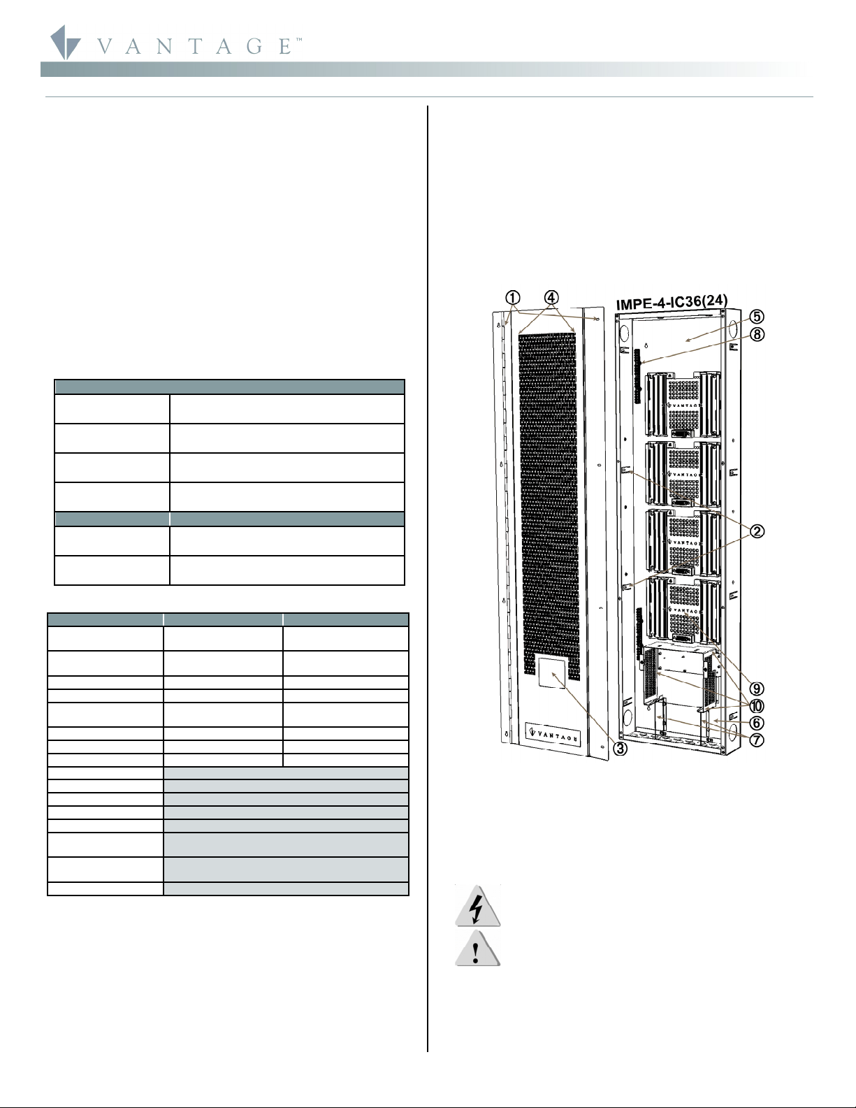
4. Use eight 1 ½” screws for mounting IMPE-4 or ISPE-4.
5. Use four 1 ½” screws for IMPE-2 or ISPE-2.
6. The enclosure door has a 1/2" lip that extends past the
enclosure sides, concealing the edge of the enclosure next
to the wall. When surface mounting the enclosure leave
sufficient space between multiple enclosures to allow the
doors to be installed and swing free from each other.
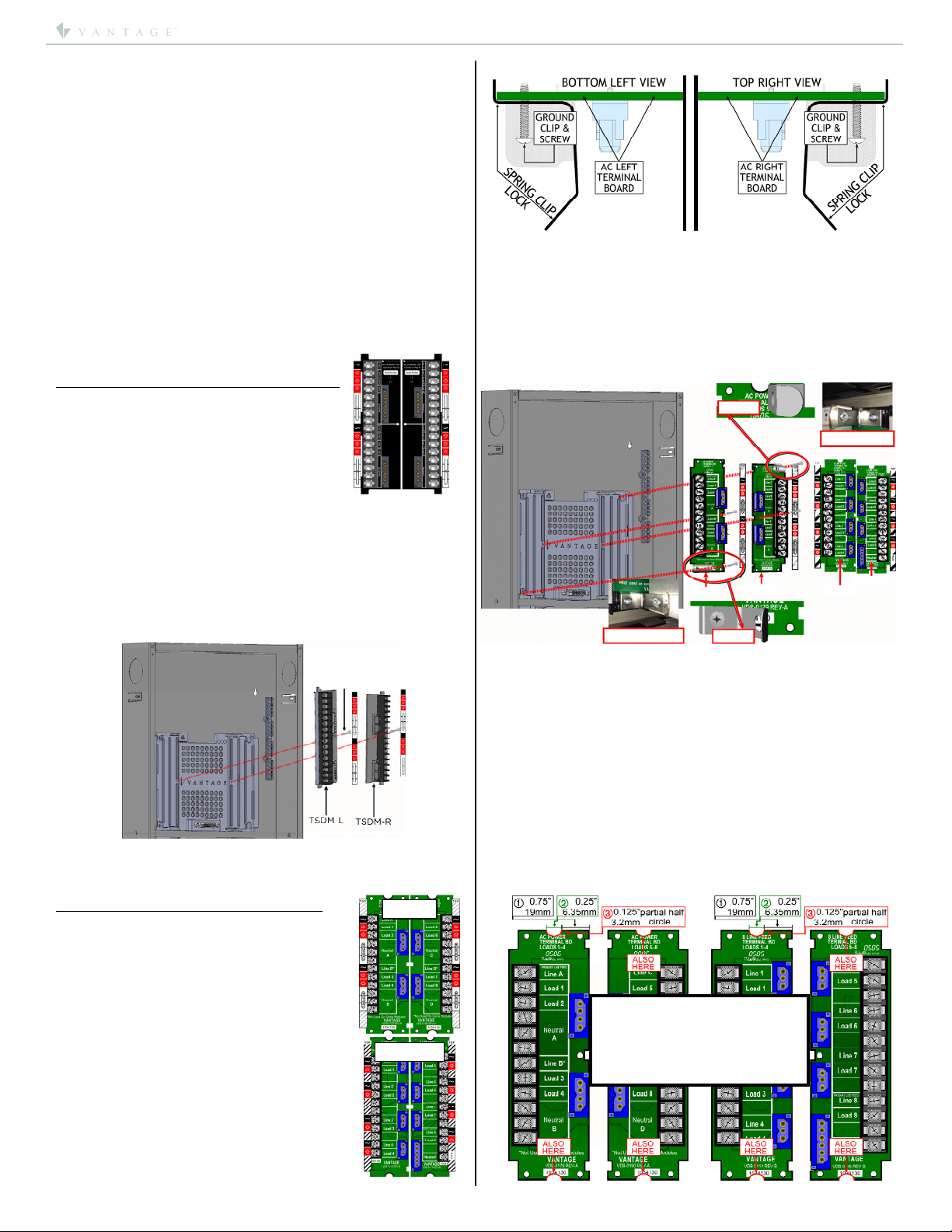
General Wiring
Enclosure conduit knockouts: Top and Bottom; 25 - 1/2"
knockouts (50 total) for wiring in the top and bottom. In the
bottom center of the enclosure, seven of the knockouts are
separated by a low voltage barrier and must only be used for
low voltage. This isolates all low voltage runs from high
voltage runs. A metal cage surrounds the Controller area of the
enclosure and is adjacent to the low voltage barrier. Left and
Right; 2 - 2” knockouts (4 total) for wiring high voltage
between enclosures through the left and right sides. Typically
these knockouts are only used in surface mount installations.
Breaker Feeds to Controllers:
Vantage recommends that the Main Controller’s power be
wired to a dedicated circuit breaker. When multiple enclosures
containing controllers are in close proximity to one another, it
is recommended to share the same breaker to all Main
Controllers; no more than nine controllers may be connected to
a 20amp breaker – allow up to 200W@120VAC per InFusion
Controller. Do not share the same breaker with controllers and
modules.
Vantage Station Bus Wire Specification
Vantage wire, part #VDA-0113 – 2C, 16AWG / 1.31mm2, twisted,
non-shielded, <30pF per foot. Separate a minimum of 12" /
30.5cm from other parallel communication and/or high voltage
runs.
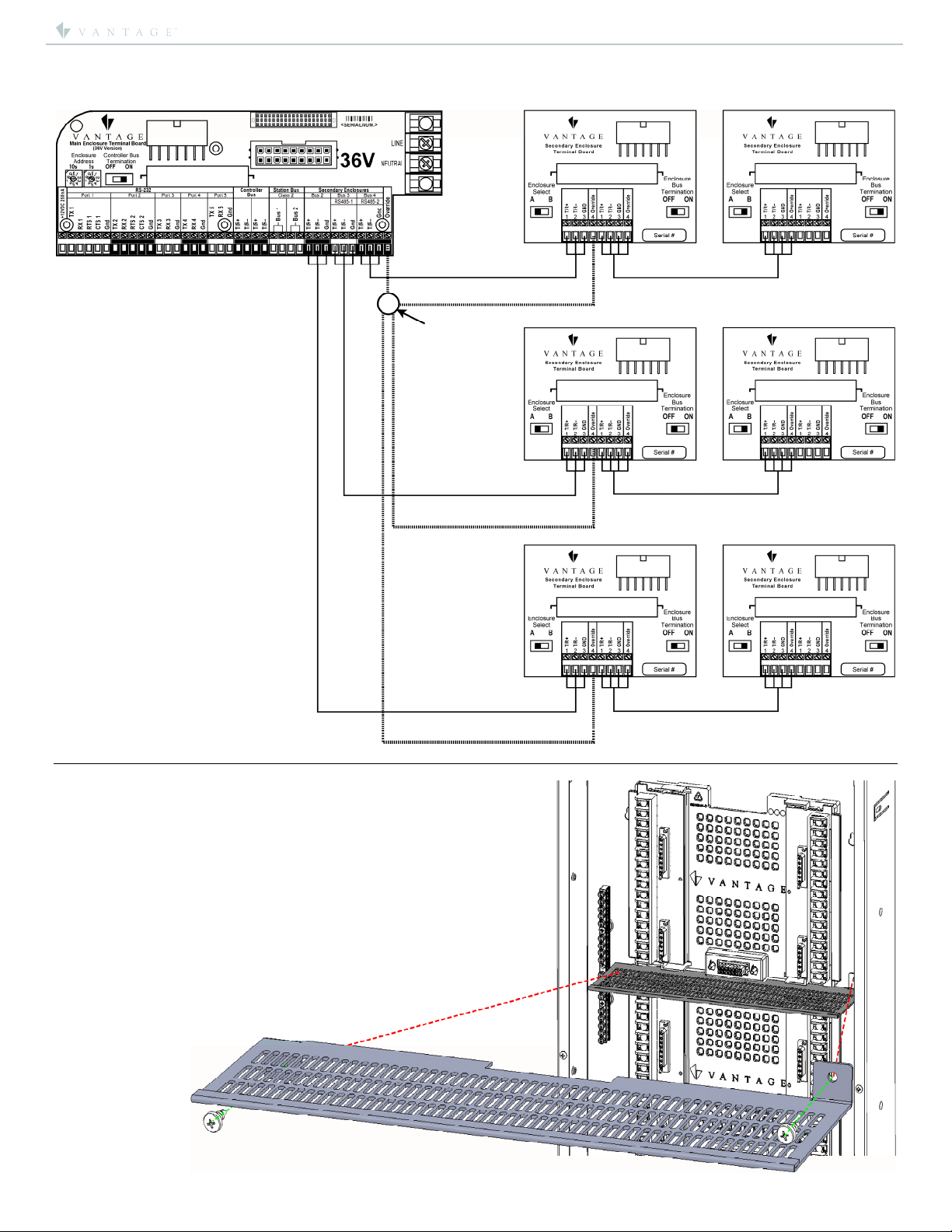
Main Controller to Main Controller Wiring
When connecting multiple Main enclosures via the Main
Enclosure Terminal Board’s Controller Bus screw terminals,
Vantage recommends their own or an equivalent wire, (see
Vantage Station Bus Wire Specification above) be used in runs
between Main enclosures. This is a polarized connection with
two “+” and two “–” screw terminals for in and out wire runs.
The maximum wire length for all controllers connected
together on one bus should not exceed 2,000ft. using the
above wire specification.
NOTE: InFusion Systems may also use Ethernet connections
for Controller to Controller communication. Please see the
InFusion Controller instruction sheet for additional information.
Station Bus Wiring
WireLink stations connect to the Station Bus screw terminals
on the Main Enclosure Terminal Board. Use Vantage station bus
wire, (above). Maximum total station bus wire for each run =
2,000 feet with no station more than 1,000 feet from enclosure
(typically the second half of the station bus loops back to
enclosure with only one end connected). Station Bus should be
separated a minimum of 12" from other parallel communication
and/or high voltage runs.
Main & Secondary Enclosure to Secondary Enclosure Wiring
Connecting a Main enclosure to a Secondary enclosure or
Secondary enclosure A to Secondary enclosure B, requires
16/18-gauge 4-conductor twisted, non-shielded wire. Three of
the wires are always used to connect a Main enclosure to a
Secondary enclosure and chained secondary enclosures. This is
a polarized connection with “+”, “–” and “Gnd” screw terminals
for communication. The 4th wire is for Manual Override and is
optional. Each Secondary enclosure bus can support two
Secondary enclosures for a maximum of six Secondary
enclosures (see InFusion wiring below) per Main enclosure.
Maximum wiring distance from Main enclosure to Secondary
enclosure is 200ft including an A/B Secondary system (e.g.,
100ft from Main enclosure to Secondary enclosure A and an
additional 100ft from Secondary enclosure A to Secondary
enclosure B).
Main Terminal Board Terminator
If only one or two Main enclosures are used, the Controller Bus
Termination switch must be ON. This switch is located on the
Enclosure Terminal Board. If more than two Main enclosures
are used ONLY the first and last Enclosure Terminal Boards on
each controller bus should have the Network Termination
switch set to ON. Example: In a five Main enclosure system,
Main Controllers 1 and 5 may not be the first and last
Controllers. The daisy-chain “wiring” order could be 2-1-3-5-4.
In this example, Main enclosures 2 and 4 are the first and last
Controllers, so only these two would have the Network
Termination switch ON, the other three must be set to OFF.
RS-232 (Ports 1-5) for Main Enclosures
The Main Enclosure Terminal Board has five RS-232 ports. Use
these ports to connect any device that uses RS-232
communication. Only connect one RS-232 device at a time to
an RS-232 port. If additional RS-232 ports are needed, Vantage
also manufactures an RS-232 Station or, some products like
the IRX II, have built-in RS-232 ports.
Vantage typically uses RX, TX and GND for communication but
does have RTS and CTS for some applications on RS-232 Ports
1 and 2. RS-232 Ports 3-5 only have TX, RX and GND., however,
all five ports can use software flow control. The default
communication protocol may be changed through Design
Center software.
Communication protocol parameter settings:
Standard baud rates 1200 – 115.2K
7-8 Data Bits
Even, Odd, Forced or No Parity
200ft. maximum wiring distance
Default protocol for RS-232 communication is:
Baud: 19200
Parity: None
Total bits: 8
Stop bits: 1
RS-485 Connections
The Main Enclosure Terminal Board has two RS-485 ports.
These ports are connected to the same screw terminals used
for Secondary enclosure ports 3 and 4. The ports may not be
used for Secondary enclosure support and RS-485 support
simultaneously. However, if Secondary enclosure bus ports 3
and/or 4 are free they may be used as RS-485 communication
ports. The RS-485 ports are half-duplex, meaning that each
port can transmit and receive but not at the same time.
Maximum wiring distance for RS-485 ports is 200ft.
Possible Ground Loop Issues
All RS-232/RS-485 connections between third party
equipment and RS-232/RS-485 connections on the Main
Enclosure Terminal Board may produce a ground loop. Most
often, the connected RS-232/RS-485 device is not using the
same power source or is far away from the Vantage enclosure
resulting in a possible ground loop that may produce a data
noise condition. If this condition is suspected, Vantage
recommends a third party RS-232/RS-485 Opto (optical)
Isolation Module. Opto Isolation provides a communications
link and is an important consideration if a system uses different
power sources, has noisy signals or must operate at different
ground potentials.
Auxiliary Power
The enclosure, Main Enclosure Terminal Board has a 12VDC
auxiliary power connection. The 12VDC connection is typically
used for one RFE1000 RadioLink Enabler or one RFLC-V232
Enabler. Total power is limited to 250ma. NOTE: Do not

I N S T A L L A T I O N
©Vantage, 8/15/2016 / IS-0536-B InFusion Power Enclosure — MODEL: IMPE-4(2)-IC36(24) & ISPE-4(2)-IC page 3 of 6
TLM-KIT
T8LRM-KIT
N
O
TE:
Top Right Clip
Top Right Scre
w
VSUB172
CLOSE UP
Top Right Clip
CLOSE UP
VSUB173
VSUB160
VSUB161
Bottom Left Clip
N
O
TE:
Bottom Left Clip
Bottom
Left Scre
w
CAUTION: In step #3, do not
cut the depth of the notches
more than 0.125” / 3.2mm
deep. The AC Boards should
fit tight from top to bottom.
connect more than one auxiliary device at a time to this power
source. If additional powered devices are needed they must be
separately powered with an external, isolated type (usually no
ground prong), power transformer.
Manual Override
In the unlikely event of a Main Controller failure, the Manual
Override can be used to turn selected loads ON. If the system
is in override, individual loads can be controlled by dip-
switches located on each module in the enclosure. Manual
Override control can be extended to other enclosures. It is
common to extend Manual Override between a Main enclosure
and its Secondary enclosures. It is not recommended to extend
Manual Override between Main enclosures.
Enclosure AC Terminal Board Types
AC Terminal boards are sold and installed separately. This
allows the installer to use different module models inside the
enclosure. Below are the different types of AC terminal boards
that may be installed in this enclosure.
Terminal Boards For SDM12 Series Modules:
Order kit part #TSDM-KIT
12 Load AC Boards TSDM-L (left) and TSDM-R
(right). Be sure to install the LEFT board’s
center screw for this module’s ground
connection.
Installing SDM12 Module Load Boards – left and TSDM-R right:
1. Insert AC terminal boards– TSDM-L left and TSDM-R right
to panel board and secure using 1, VHD-0082, #6-32 X
7/8" PHILLIPS PAN HEAD THREAD FORMING screws
(TYPE-F) on each board.
a. Left board is also the ground connection for the
SDM12-EM module – it must connect to the
enclosure – be careful not to strip self-tapping
threads or damage AC terminal board.
2. Place module load labels on left and right sides of the AC
panel board using care to align with screw terminals.
3. Enclosure section is now ready for wiring.
AC Terminal Boards For Legacy Modules:
Order Kit part #TLM-KIT
MDS8RW101/102 Dim
MDR8RW101/102 Relay
EDIMMOD Electronic Dim
FANMOD Ceiling Fan
SD4008A-120 Dim
SD9008A-277 Dim
AR8008-120 Relay
Order Kit part #T8LRM-KIT
MDR8CW301 Commercial 8-Linefeed, Relay
Be sure to use top left and bottom right
outside screws with all Legacy sets to
accommodate the top and bottom steel-spring
module clips.
Installing Legacy Module Load Board Clips:
Insert AC terminal boards to panel board and secure using
2, VHD-0082, #6-32 X 7/8" PHILLIPS PAN HEAD THREAD
FORMING screws (TYPE-F) on each board. The bottom left
and top right screws should also include the module
spring-clip to lock the module in and provide the module’s
ground source.
NOTE: IMPORTANT, The bottom left and top right
spring-clips and screws are ground connections for the
module. Note the orientation of the clip locks!
Enclosure section is now ready for wiring.
*NOTE: If using a slightly older version of the VSUB172 (left)
and VSUB173 (right) or the VSUB160 (left) and VSUB161 (right)
AC Boards, it will be necessary to cut a slight notch out at the
top and bottom of the board as illustrated below. This will
allow the AC terminal boards to fit into the new Terminal
Board Module Platform, part number 103160.
How To Notch Old Terminal Boards For Use In New Enclosures
STEPS:
1. From the AC Board’s (blue) connectors side measure in
0.75” / 19mm and mark;
2. From that mark measure another 0.25” / 6.35mm and mark;
3. Cut a 0.25” / 6.35mm X 0.125” / 3.2mm partial half-circle
notch out of the board on the top and bottom of both the
left and right hand AC boards as illustrated on next page.
Notching Old AC Terminal Boards
Ground
Screw!

I N S T A L L A T I O N
©Vantage, 8/15/2016 / IS-0536-B InFusion Power Enclosure — MODEL: IMPE-4(2)-IC36(24) & ISPE-4(2)-IC page 4 of 6
Main Enclosure
Multi-View
Shipping may
have loosened
Wiring Harness
Pins. Please
make sure they
are securely
inserted into the
proper holes.
TORQUE: 20 INCH
POUNDS
PROPER: Wire not forced
in screw terminal too far.
PROPER: Insulation
not cut back too far.
Make a small notch at the top and bottom as illustrated using
directions on previous page
Wiring AC Terminal
Boards
Keep breaker and load
wire runs organized
and managed as
illustrated.
Neutrals
Run a separate NEUTRAL for each load connected to dimming
devices. Failure to do this may cause loads, sharing the same
neutral, to flicker slightly while ramping or dimming a load. The
potential for flickering occurs with all dimming systems due to
the changing load level coupling to the fixed load through the
neutral.
Proper High Voltage Terminations / Proper Torque:
CONNECTOR TORQUE WIRE RANGE
MODULE TERMINAL 20 INCH POUNDS 14-10 AWG*
CONTROLLER POWER 20 INCH POUNDS 14-10 AWG*
*MUST MATCH BREAKER WIRE GAUGE
Enclosure Drawings

I N S T A L L A T I O N
©Vantage, 8/15/2016 / IS-0536-B InFusion Power Enclosure — MODEL: IMPE-4(2)-IC36(24) & ISPE-4(2)-IC page 5 of 6
Torque: 20 inch pounds
Wire Range: 14-10 AWG*
(*Must match breaker wire gauge)
The InFusion Controller Plugs into the
Main Enclosure Terminal Board after
all connections have been made.
Wiring Key
1. RS232 Ports + Flow Control
2. RS232 Ports – Flow Control (software Flow Control through Design Center)
3. Previous Controller Bus
4. Next Controller Bus
5. Station Bus Run-1
6. Station Bus Run-2
7. To Secondary Enclosure Board (A) Switch
8. RS485 Ports (If not used for Secondary Enclosure Bus)
(See maximum wire lengths above)
CAUTION: For retrofit jobs, this board is also available in a 24V version for the IC-24-1
Controller. NEVER connect stations that do not display a circle symbol on the
Serial Number sticker to an IC-36-1 System.
Wire Types Key
6C 18-24AWG
2C 18-16AWG
4C 18AWG
InFusion Main Enclosure Terminations:
InFusion Secondary Enclosure Terminations:
InFusion Override Wiring Examples:
To InFusion
Enclosure Board
(4C 16-18AWG)
To InFusion Secondary
Enclosure Board Switch-B
(4C 16-18AWG)

I N S T A L L A T I O N
©Vantage, 8/15/2016 / IS-0536-B InFusion Power Enclosure — MODEL: IMPE-4(2)-IC36(24) & ISPE-4(2)-IC page 6 of 6
InFusion Main Enclosure
to Secondary Enclosure
Wiring Overview
Note the position of the Enclosure Selec
t
switch and the Enclosure Bus Termination
switch on each Secondary Enclosure
Terminal Board. All “A” boards are
homerun to the Controller board and all “B”
boards are homerun to its Parent, “A”
board. The termination switch is OFF for all
“A” boards only if they have a “B” board
connected. The termination switch is On
for all “B” boards.
Junction for all
Overrides
It is also possible to
extend Override from
one Secondary
Enclosure to the next
Secondary Enclosure,
as long as it daisy-
chains back to the
Main Enclosure.
Enclosure High Voltage Divider
If an Enclosure is using two different voltages (e.g., 120Volts and 277Volts),
use the InFusion Power Enclosure Voltage Divider, part number IPEVD.
This barrier is installed between modules with self-tapping screws as
illustrated. The different voltages must enter the enclosure from the correct
side of the IPEVD. Because the Controller does not support 277Volts, it is
recommended that the 277V enter through the TOP of the Enclosure and
the 120V enter from the BOTTOM left and right sides. Remember the
bottom center section is only for Low-Voltage connections to the
controller. Build the enclosure in Design Center to best accommodate this
part when different high voltages will enter the enclosure.
Detail Wiring InFusion Main Enclosures to
InFusion Secondary Enclosures
(See wire specifications above)
InFusion Enclosure High Voltage Divider, Part Number IPEVD
This manual suits for next models
8
Other Vantage Hearth Enclosure manuals
Popular Enclosure manuals by other brands

Streak
Streak Ultra ETORQUE X1 user manual

LEGRAND
LEGRAND CHIEF PAC527L Series installation instructions

Macpower & Tytech
Macpower & Tytech Pleiades USB/LAN User manual & installation guide

StarTech.com
StarTech.com InfoSafe IDECASE35U2 instruction manual

LST
LST LAT288-1 Specification sheet

BARTEC FEAM
BARTEC FEAM ESA Series Instructions for use