Vega Absolute MT-5 CAN User manual

www.vega-absolute.ru
GNSS TRACKER
VEGA MT-5 CAN
User Manual
REVISION NUMBER FIRMWARE VERSION
04 0.10b rc41.8

Vega MT-5 CAN / User Manual
2
Revision № 04 of 01 July 2022
CONTENTS
INTRODUCTION............................................................................................................................................................................ 3
1 DESCRIPTION AND OPERATION ............................................................................................................................................. 4
Device description .................................................................................................................................................................... 4
Functionality .............................................................................................................................................................................. 4
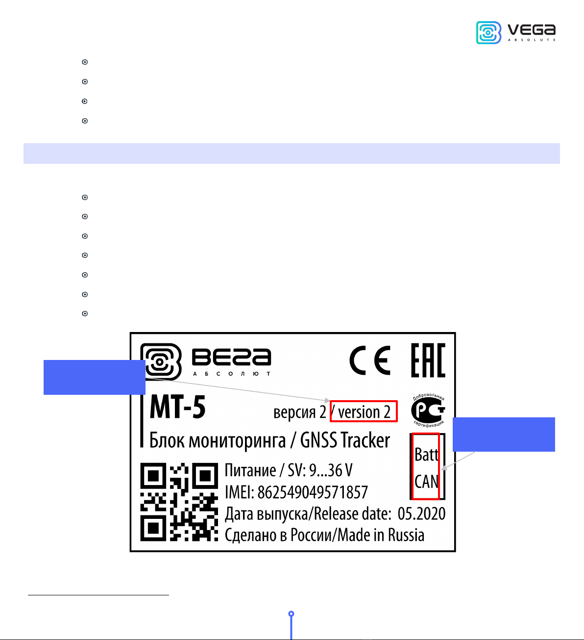
Marking........................................................................................................................................................................................ 5
2 SPECIFICATION........................................................................................................................................................................... 6
3 OPERATION BEGINNING .......................................................................................................................................................... 7
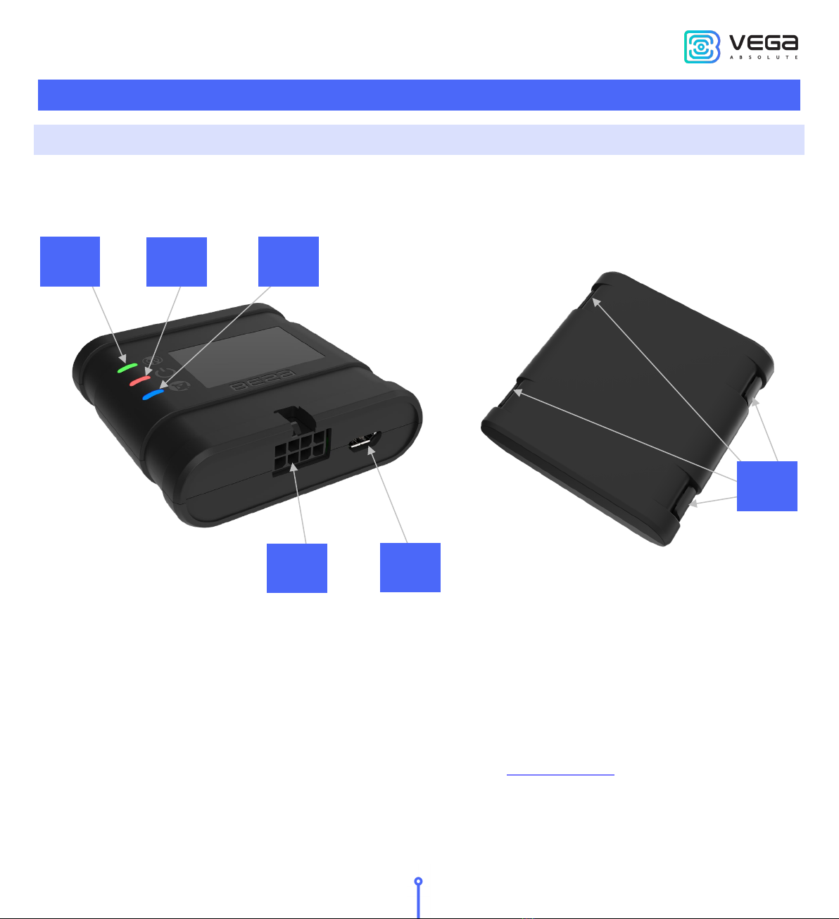
Device appearance ................................................................................................................................................................... 7
Contacts description ................................................................................................................................................................ 8
Device indication....................................................................................................................................................................... 9
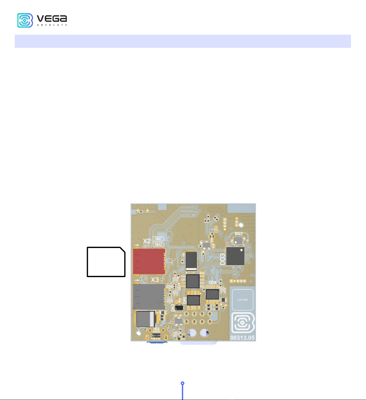
SIM installing ............................................................................................................................................................................ 10
Mounting recommendations................................................................................................................................................ 12
4 EXTERNAL EQUIPMENT CONNECTION............................................................................................................................... 14
Dallas temperature sensors................................................................................................................................................... 14
Authorized Dallas keys ........................................................................................................................................................... 15
Switching inputs CAN/RS-485.............................................................................................................................................. 16
Fuel level sensors .................................................................................................................................................................... 16
Extension unit .......................................................................................................................................................................... 17
Actuators................................................................................................................................................................................... 17
Inputs......................................................................................................................................................................................... 19
BLE-sensors.............................................................................................................................................................................. 20
5 COMMUNICATION PROTOCOLS.......................................................................................................................................... 21
6 MANAGING USING SMS-COMMANDS ................................................................................................................................. 22
7 STORAGE AND TRANSPORTATION REQUIREMENTS........................................................................................................ 26
8 CONTENT OF THE PACKAGE................................................................................................................................................. 27
9 WARRANTY ................................................................................................................................................................................ 28

Vega MT-5 CAN/ User Manual
3
Revision № 04 of 01 July 2022
INTRODUCTION
This manual is designated for Vega MT-5 CAN series GNSS tracker (hereinafter – the device)
manufactured by Vega-Absolute OOO and provides information on powering and activation procedure,
control commands and functions of the device.
This manual is targeted at specialists which familiar with installation and repairing procedures rules for
motor transport and had holding of professional knowledges in the field of electronic and electrical
equipment of different vehicles.
The device shall be installed and adjusted by qualified specialists to ensure
proper operation of the device
For successful using of the device, you should learn monitoring system principle of operation in
complex and understand the function of every its part.
Vega-Absolute OOO reserves the right to make changes to the manual related to the improvement of
equipment and software, as well as to eliminate typos and inaccuracies, without prior notice.

Vega MT-5 CAN / User Manual
4
Revision № 04 of 01 July 2022
1 DESCRIPTION AND OPERATION
DEVICE DESCRIPTION
Vega MT-5 CAN device is designed for monitoring of vehicles by the using of GLONASS/GPS
positioning systems including the determination of vehicle placement, speed, and motion direction as well as
for transmitting of collected data through GSM.
Vega MT-5 CAN uses the processor with a supporting up to three CAN-buses that allows to get a full
information about vehicle.
The vehicle route is recorded as individual points in time (track). Along with the track, information is
recorded coming into the device from internal and external sensors, as well as from an additional equipment.
Non-volatile memory allows to store information about events and statuses of the device in the absence of
power supply. Support of several servers allows to send information about vehicle status on the four servers
simultaneously.
You can configure the device by SMS commands or through the “Configurator” application while the
device connected with USB or by the air with TCP connection. Application also allows update a firmware and
carry out the finest tuning such as operation scenarios for external equipment or CAN bus, features of fixing,
recording, and transmitting of packets and many other. You can download application on the site in
“Software” section and there is a Manual for work with “Configurator”. Go to the program page.
FUNCTIONALITY
Vega MT-5 CAN provides the following functionality:
Wialon IPS, Wialon Combine, VEGA protocols supporting
Simultaneous operation with four servers through any of supported protocol
Device activity can be programming by the “Scenarios” function
Configuration through GPRS, USB
Firmware updating through GPRS, USB
Remotely configuring and monitoring of status through free engineer server
Driver identification by the I-Button keys
Temperature control at the engine compartment and the car salon with an external 1-Wire
sensors
Manage of actuators by the commands and by the events

Vega MT-5 CAN/ User Manual
5
Revision № 04 of 01 July 2022
Built-in black box holding up to 50 000 entries
GPS-odometer
Trip counter
Remotely diagnostic of the device status
MARKING
Device marked with sticker that contain the following information:
Device name (МТ-5);
Device version (for example version 2);
Device model (for example, CAN1, CAN Batt etc.);
Power supply nominal;
IMEI – individual number is used as device ID – is placed on sticker as number and QR-code;
Release Date;
Country of origin, trademark.
Sticker located in three places – on device case, in factory certificate and on the packing box.
1For models with the corresponding sticker, software selection of the CAN or RS-485 interface is provided
Device model
Device version

Vega MT-5 CAN / User Manual
6
Revision № 04 of 01 July 2022
2 SPECIFICATION
Parameter Value
Batt CAN Batt CAN
Housing dimensions, mm
59 х 60 х 18
Ingress protection rating
IP53
External power, V 9…36
Consumption current, mА
- in sleep mode
- in active mode
up to 5
40…300
Operating temperatures, °С
─
40…+85
Built-in battery
no
yes
no
Interfaces RS-485 CAN or RS-485 software
interface selection
Multifunctional inputs
1
Digital output
1
1-Wire 1
Ignition control input
1
Built-in accelerometer
Yes
GSM and GLONASS/GPS antenna Built-in
GSM/GPRS and GNSS module
SIM868E
GSM: 850/900/1800/1900 MHz
GPRS class 12 85.6 Kbit/sec
GNSS: GLONASS/GPS/Galileo/QZSS
Sensibility: -166dBm
Bluetooth
BT3.0 + BLE
SIM 2 SIM cards
USB
micro-USB, type B
Built-in black box
up to 50 000 entries

Vega MT-5 CAN/ User Manual
7
Revision № 04 of 01 July 2022
3 OPERATION BEGINNING
DEVICE APPEARANCE
Vega MT-5 CAN is represented in black plastic case which has four screws and mounting eyelets. On
the case there are LED indicators signed by pictograms, wire connector and USB. Depend on device version
there might be connectors for external antennas GSM and GNSS.
1 – LED indicator of GSM connection (green)
2 – LED indicator of power (red)
3 – LED indicator of GNSS module (blue)
SIM slots are placed on the PCB inside the case (see part «SIM installing»).
1 2 3
6
4 5
4 – wire connector
5 –USB connector
6 – mounting eyelets

Vega MT-5 CAN / User Manual
8
Revision № 04 of 01 July 2022
CONTACTS DESCRIPTION
2Software selection of CAN or RS-485 interface for models marked "CAN" in the sticker
3Software selection of CAN or RS-485 interface for models marked "CAN" in the sticker
Contact
Wire color
Description
1
Black Ground -
2
White + dark blue Multifunctional input
3
Orange 1-Wire
4
Black + white CAN1 Low2/ RS-485 A
5
Red Power +
6
Yellow Input of ignition control
7
Dark blue Digital output
8
Black + red CAN1 High3/ RS-485 B

Vega MT-5 CAN/ User Manual
9
Revision № 04 of 01 July 2022
DEVICE INDICATION
The device has three LED indicators. Blue indicator shows the navigation receiver status. Red
indicator shows the presence of an external power. Green indicator shows GSM-connection status.
LED signal Meaning
Blue glowing Navigation receiver in the mode of
sputnik tracking. Location determined.
Blue flashing one
per second
Location determination in progress.
Red glowing External power supplying on.
Red flashing External power supplying off.
Green not glowing GSM-signal absent.
Green glowing The device is in range of a GSM
network.
Green flashing GSM data exchange in progress.

Vega MT-5 CAN / User Manual
10
Revision № 04 of 01 July 2022
SIM INSTALLING
To use the Vega MT-5 CAN GNSS tracker, you need a nano-SIM with support of SMS and GPRS
functions. There must be cash on the account. PIN protection must be disabled.
The device supports the ability to use two SIM cards. In this case, one of them will perform the reserve
function, and will be used only if it is not possible to send data from the first main SIM.
The devices have their own algorithm for SIM-card switching from main to reserve and back:
1) The device cannot join to the network for the 5 minutes while it operates with main or reserve SIM-
card;
2) If 16 unsuccessful attempts were made to establish a TCP connection to each server (not disabled
in the settings);
3) If a TCP connection is established, but there is no data at the application level from the servers for
the 5 minutes.
The location of the primary and secondary SIM slots is shown in the figure below, the primary slot is
highlighted in red.
SIM

Vega MT-5 CAN/ User Manual
11
Revision № 04 of 01 July 2022
To avoid damage and malfunction, it is recommended to perform all
manipulations with the PCB when it is de-energized
To install the SIM you must perform the following steps:
1) remove the top cover of the device and de-energize the PCB by carefully disconnecting the
battery;
2) remove the PCB – SIM holders are located on the reverse side of the PCB;
3) insert the SIM into the holder;
4) assemble the device.

Vega MT-5 CAN / User Manual
12
Revision № 04 of 01 July 2022
MOUNTING RECOMMENDATIONS
Before installing the block on an object, it is necessary to perform basic connection settings to be
able to connect to the block remotely via TCP. Connection settings are:
monitoring servers’ settings (protocol, IP-address and port);
network settings (SIM access point settings);
settings for transmitting readings (information that will be transmitted to the server).
Initial configuration is carried out through USB-port with Configurator application. For this you
should do the following steps:
1. Install the main SIM-card (see part "SIM Installing").
2. Connect the device to a PC through USB-port located on the front panel.
3. Run the Configurator application on the PC, press “Connect” button and choose the connection
method like “Connect through USB”.
4. On the left menu choose “Settings”.
5. Make connection settings.
Pay attention to the settings for connecting to the engineering server using the
VEGA protocol. These parameters will be used when connecting to the device
remotely through the Configurator program
6. After setting connection parameters press the “Save” button.
7. Disconnect USB-cable.
8. Try test connection through the air for checkup of the connection parameters.
9. If the connection is successfully done, then the device is ready for installing on a vehicle.
For mounting you will need:
wires and fuse which are included in a package;
fuse;
wire stripper;
laptop.

Vega MT-5 CAN/ User Manual
13
Revision № 04 of 01 July 2022
Step by step mounting is as follows:
1. De-energizing the connected equipment and the vehicle's on PCB power.
2. Connection of Ignition wire4to tracker (input 6).
3. Connection of external power wires according to the scheme through a fuse.
4. Power ON.
5. Connection of an external equipment, sensors, and configuration of them (see part "External
equipment connection").
6. Device configuration, CAN bus operation if it is needed.
7. By the laptop you can make sure that the device is successfully configurated and sends the
correct data.
8. Mounting of the device with zip ties.
General recommendations for the placement of antennas boil down to two rules: avoid covering the
GSM antenna with metal parts of the vehicle and, if possible, provide a line of sight to satellites (i.e.,
open skies).
4Connecting the Ignition wire is a necessary step for the functions of monitoring and charging battery

Vega MT-5 CAN / User Manual
14
Revision № 04 of 01 July 2022
4 EXTERNAL EQUIPMENT CONNECTION
DALLAS TEMPERATURE SENSORS
Vega MT-5 CAN GNSS tracker allows to connect is up to ten Dallas temperature sensors through 1-
Wire interface. Connection scheme is on the picture below. If connected temperature sensor has three
contacts instead of two, then you should close “Power” with “Ground”.
For the device to recognize the connection of a new sensor, it is necessary to connect to the device
through the "Configurator" program, go to the “Settings” menu -> "Inputs/outputs" tab and select the "Dallas
temperature sensors" setting item.
To distinguish sensors after connection, it is recommended to connect them one at a time. Having
connected the first sensor according to the diagram above, click the "Add sensors" button. An information
window will appear.
Click “OK” - the sensor number will be added to the free field. After that you can connect the next
sensor in the same way.

Vega MT-5 CAN/ User Manual
15
Revision № 04 of 01 July 2022
You can also connect several sensors in turn, while the add window is open, in this case, after clicking
the "OK" button, the sensors will be put into free fields in the order in which they were connected.
After connecting all temperature sensors, you must click the “Save” button to put information about
sensors into device memory.
AUTHORIZED DALLAS KEYS
Vega MT-5 CAN GNSS tracker allows you to connect an I-Button authorized key reader to a 1-Wire
pin. The connection scheme is shown in the figure below. The number of authorized keys can reach ten. To
add a key, you need to connect to the device through the "Configurator" program and go to the “Settings”
menu -> "Security" tab.
In the "Security" tab, expand the "Authorized Dallas keys" settings item and click the "Add Dallas keys"
button. A dialog box will appear.
Attach the key to the reader as during authorization - the device will remember the key number - and
click "OK". The key number appears in the free field. If several keys are added at the same time, it is allowed
to attach them to the reader in turn, while the add window is open, and only then click “OK” - the numbers of
all keys will be added to the free fields in the order in which they were applied to the reader.
Click the “Save” button to put information about keys into device memory.

Vega MT-5 CAN / User Manual
16
Revision № 04 of 01 July 2022
SWITCHING INPUTS CAN/RS-485
GNSS tracker MT-5 version 2 with CAN-bus support by default uses outputs 4 and 8 to work with CAN.
To use inputs 4 and 8 as RS-485 interface you need to connect to the device through the
“Configurator” program and go to the “Settings” menu -> “Inputs/Outputs” tab.
Find the settings item "Additional interface settings" and check the box "Use CAN as RS-485".
FUEL LEVEL SENSORS
GNSS tracker allows you to connect fuel level sensors via the RS-485 bus and operates with them
using the LLS protocol.
To do this, you need to connect to the device through the “Configurator” program and go to the
“Settings” menu -> “Inputs/Outputs” tab. For each connected fuel level sensor, it is necessary to select “Sensor
Type” - RS-485 and specify the sensor address on the bus in the “Bus Address” field. The specified address
must match the address specified when the sensor programming (see instructions for the used sensor).
Up to four fuel level sensors can be connected simultaneously.

Vega MT-5 CAN/ User Manual
17
Revision № 04 of 01 July 2022
Click the “Save” button to put information about sensors into device memory.
EXTENSION UNIT
The Vega MT-5 CAN GNSS tracker allows you to connect the Vega BR-1 expansion unit via the RS-485
interface. Vega BR-1 has 15 multifunction inputs and 15 digital outputs.
To configure the inputs, you must connect to the device through the “Configurator” program, go to
the “Settings” menu -> “Inputs/Outputs” tab and select the “Input/output extension unit”. Next, you need to
select the connection interface - RS-485. After that, you can configure multifunctional inputs in accordance
with the desired tasks.
To configure the outputs, it is necessary to connect to the device through the “Configurator” program,
go to the “State” menu -> “Input/output expansion unit” tab. At the very bottom of the I/O list of the expansion
unit are the digital output controls - the “On” and “Off” buttons.
ACTUATORS
Actuators are connected to the device via digital output which are of the type “Open collector”.
So, for example, you can connect a relay for blocking the engine/petrol pump/ignition, etc. After
connecting the relay according to the scheme, you can send commands to the device to block or unblock
the relay (see the section "SMS commands", command setout).
Permissible load on each digital output 0.5 A

Vega MT-5 CAN / User Manual
18
Revision № 04 of 01 July 2022
To increase the load on the outputs of the device, you must use an external relay. The relay connection
diagram is shown below.
By default, after a device reboot, the state of the digital output is reset to 0, that is, "off". In the settings,
it is possible to save the state of the device output and digital outputs of the connected extension unit.
To do this, you need to connect to the device through the “Configurator” program, go to the “Settings”
menu -> “Inputs/Outputs” tab and select the “Restoring output states after reboot”. Opposite the desired
output, select "restore" in the drop-down menu. Then, after a reboot, this digital output will be restored to the
state that was written to the non-volatile memory of the device before the reboot.
Writing of statuses into non-volatile memory carried out at every 30 seconds

Vega MT-5 CAN/ User Manual
19
Revision № 04 of 01 July 2022
INPUTS
Vega MT-5 CAN GNSS tracker has three multifunctional inputs that can operate in four modes:
Analog;
Digital;
Frequency;
Pulse.
In analog mode, the input voltage is measured. Such an input can be used for sensors whose readings
vary in a certain range.
In digital mode, the input signal level (0 or 1) is measured. Such an input can be used for logic sensors,
the readings of which are determined by two states (on/off).
In frequency mode, the frequency of the pulse signal is measured. Such an input, for example, is
convenient to use for a car tachometer.
In pulse mode, the number of pulses at the input is counted. Such an input can be used for flow rate
sensors, for example, fuel consumption.
In the settings of multifunctional inputs in the “Configurator” program, in addition to selecting a mode
for each input, there is a parameter called “Active Level”. It can take the value “low” and “high” and
characterizes the magnitude and direction of the input tightening.
Input type
Low active level
High active level
Analog Pull-down to the ground 240 kOhm Pull-down to the ground 240 kOhm
Digital
Pull-up to external power 44 kOhm
Pull-down to the ground 240 kOhm
Pulse
Pull-up to external power 44 kOhm
Pull-down to the ground 240 kOhm
Frequency Pull-up to external power 44 kOhm Pull-down to the ground 240 kOhm
Pull-up to external power cannot be carried out while battery powered device
When the device is restarted, the multifunction input is pulled to the ground

Vega MT-5 CAN / User Manual
20
Revision № 04 of 01 July 2022
BLE-SENSORS
Bluetooth does not work without a SIM card and whenever if the GSM modem is
disconnected
Up to 5 sensors can be connected. For this it is necessary to connect to the device through the
“Configurator” program and go to the «Settings» -> tab «Settings BT/BLE». There you can make Bluetooth
scanning and create sensor from the list of discovered sensors because of scanning by context menu or
button “Create BLE-sensor”.
Supported types of BLE-sensors.
BLE beacon – MAC binding tag;
Neomatika ADM31/ADM35 – sensor of temperature, humidity, ambient light level;
Neomatika ADM32 – angle sensor;
Escort TD-BLE – fuel level sensor;
Escort TT-BLE – temperature sensor;
Escort TL-BLE – sensor of temperature, ambient light level;
Escort DU-BLE – angle sensor;
Escort TH-BLE – sensor of temperature, humidity, ambient light level, pressure.
Table of contents
Other Vega Absolute GPS manuals