Velatia Ormazabal ormaSET-M Instruction manual

ormaSET-M
General Instructions
IG-199-EN, version 03; 6/11/2013
Prefabricated metallic transformer substation

Legal Deposit: BI-1401/2013
CAUTION!
When medium-voltage equipment is operating, certain components are live, other parts may be in movement, and some may reach high
temperatures. Therefore, the use of this equipment poses electrical, mechanical and thermal risks.
In order to ensure an acceptable level of protection for people and property, and in compliance with applicable environmental
recommendations, Ormazabal designs and manufactures its products according to the principle of integrated safety, based on the
following criteria:
· Elimination of hazards wherever possible.
· Where elimination of hazards is neither technically nor economically feasible, appropriate protection functions are
incorporated in the equipment.
· Communication about remaining risks to facilitate the design of operating procedures which prevent such risks, training
for the personnel in charge of the equipment, and the use of suitable personal protection equipment.
· Use of recyclable materials and establishment of procedures for the disposal of equipment and components so that once
the end of their service lives is reached, they are duly processed in accordance, as far as possible, with the
environmental restrictions established by the competent authorities.
Consequently, the equipment to which the present manual refers complies with the requirements of section 11.2 of the forthcoming
IEC standard 62271-1. It must therefore only be operated by appropriately qualified and supervised personnel, in accordance with the
requirements of standard EN 50110-1 on the safety of electrical installations and standard EN 50110-2 on activities in or near electrical
installations. Personnel must be fully familiar with the instructions and warnings contained in this manual and in other recommendations
of a more general nature which are applicable to the situation according to current legislation.
The above must be carefully observed, as the correct and safe operation of this equipment depends not only on its design but also on
general circumstances which are in general beyond the control and responsibility of the manufacturer. More specifically:
· The equipment must be handled and transported appropriately from the factory to the place of installation.
· All intermediate storage should occur in conditions which do not alter or damage the characteristics of the equipment or
its essential components.
· Service conditions must be compatible with the equipment rating.
· The equipment must be operated strictly in accordance with the instructions given in the manual, and the applicable
operating and safety principles must be clearly understood.
·Maintenance should be performed properly, taking into account the actual service and environmental conditions in the
place of installation.
The manufacturer declines all liability for any significant indirect damages resulting from violation of the guarantee, under any
jurisdiction, including loss of income, stoppages and costs resulting from repair or replacement of parts.
Guarantee
The manufacturer guarantees this product against any defect in materials and operation during the contractual period. In the event that
defects are detected, the manufacturer may opt either to repair or replace the equipment. Improper handling of this equipment and its
repair by the user shall constitute a violation of the guarantee.
Registered Trademarks and Copyrights
All registered trademarks cited in this document are the property of their respective owners. The intellectual property of this manual
belongs to the manufacturer.
In view of the constant evolution in standards and design, the characteristics of the elements contained in this manual are subject to
change without prior notification.
These characteristics, as well as the availability of components, are subject to confirmation by Ormazabal.

3
ÍndiceGeneral Instructions
ormaSET-M
IG-199-EN version 03
ÍNDICE
1 Description and main characteristics 4
1.1 Switchgear and control gear . . . . . . . . . . . . . . 4
2 Service conditions 6
3 Dimensions and weights 7
4 Transport 8
4.1 Road transport . . . . . . . . . . . . . . . . . . . . . . . . 8
4.2 Sea transport . . . . . . . . . . . . . . . . . . . . . . . . . . 8
4.3 Packing . . . . . . . . . . . . . . . . . . . . . . . . . . . . . . 8
5 Installation 9
5.1 Location . . . . . . . . . . . . . . . . . . . . . . . . . . . . . . 9
5.2 Planning . . . . . . . . . . . . . . . . . . . . . . . . . . . . . 9
5.3 Preparing the ground . . . . . . . . . . . . . . . . . . . 9
5.4 Handling . . . . . . . . . . . . . . . . . . . . . . . . . . . . 10
5.5 Cable access and sealing . . . . . . . . . . . . . . . 10
5.6 Earthing circuit connection . . . . . . . . . . . . . . 10
5.6.1 Earth Circuit . . . . . . . . . . . . . . . . . . . . . . . . . 11
5.6.2 Service Earth (Neutral) . . . . . . . . . . . . . . . . . 11
6 Replacement electrical equipment 12
6.1 Medium voltaje switchgears and low voltage
switchboard substitution . . . . . . . . . . . . . . . . 12
6.2 Transformer substitution . . . . . . . . . . . . . . . 12
7 Operation 13
8 Substation maintenance 14

4 Description and main characteristics General Instructions
ormaSET-M
IG-199-EN version 03
1 Description and main characteristics
Ormazabal's ormaSET-M is a kiosk-type Metallic
Prefabricated Transformer Substation, installed on surface
and externally operated, with reduced dimensions,
standard-built, factory tested and supplied from the factory
as a unit.
ormaSET-M Transformer Substation complies with the
requirements established in standard IEC 62271-202.
ormaSET-M is designed for end-user networks with rated
voltages Urup to 36 kV and a rated power of 1000 kVA.
Ormazabal's ormaSET-M Transformer Substation is made
up of the following main components:
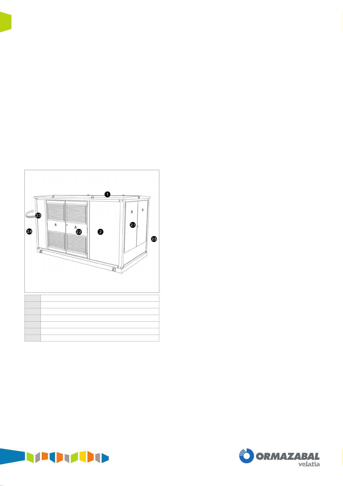
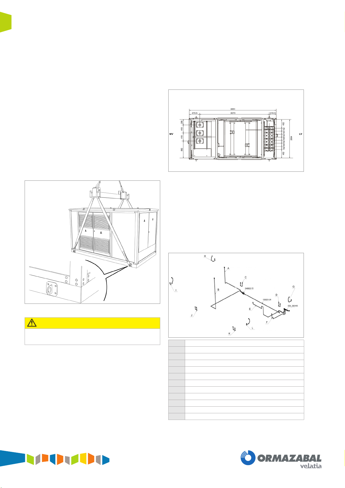
Fig. 1.1: Main Components of ormaSET-M
It is characterised by the incorporation of medium voltage
(MV) equipment for public distribution networks up to
36 kV. It has independent accesses for the medium voltage
switchgear compartment, for the transformer compartment
and for the low voltage switchboard compartment.
Made up of:
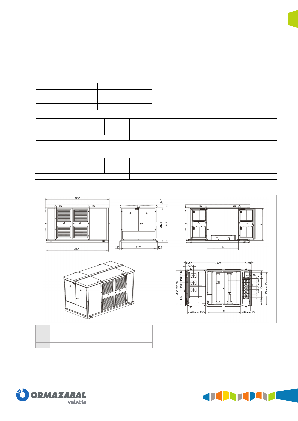
►Metal prefabricated enclosure.
►Removable roof dimensions 4046 x 2275 mm.
►Access doors to the electrical switchgear:
□Double access doors and dimensions of
997 x 1400 mm in the medium voltage area and
low voltage board area. Folding doors at 90º and
180° on the outside wall, hinged, with a two fixing
point and a fastening rod to hold them open
preventing untimely closures.
□Snow panel below medium voltage and low
voltage doors, dimensions 1997 x 486 mm.
□Access doors to the Transformer: Two accesses
to the transformer, one on either side, made up of
double doors of 963 x 1890 mm, folding at 90º
and 180° on the outside wall, hinged, with a two
fixing point and a fastening rod to hold them open
preventing untimely closures.
►Air intake and exhaust grille for natural ventilation,
fitted with a grille of 6 x 6 mm.
►Optionally, a closing system for the medium voltage
input cables in the lower part of the enclosure. Up to
3 input cables for 3 x 1 x 240 mm2XLPE 18/
30 kV H16. Maximum single core cable diameter
90 mm.
►Optionally, a closing system for the low voltage
input cables in the lower part of the enclosure. Up to
8 input cables for 4 x 1 x 240 mm2XZ1 0.6/1 kV.
Maximum single core cable diameter 90 mm.
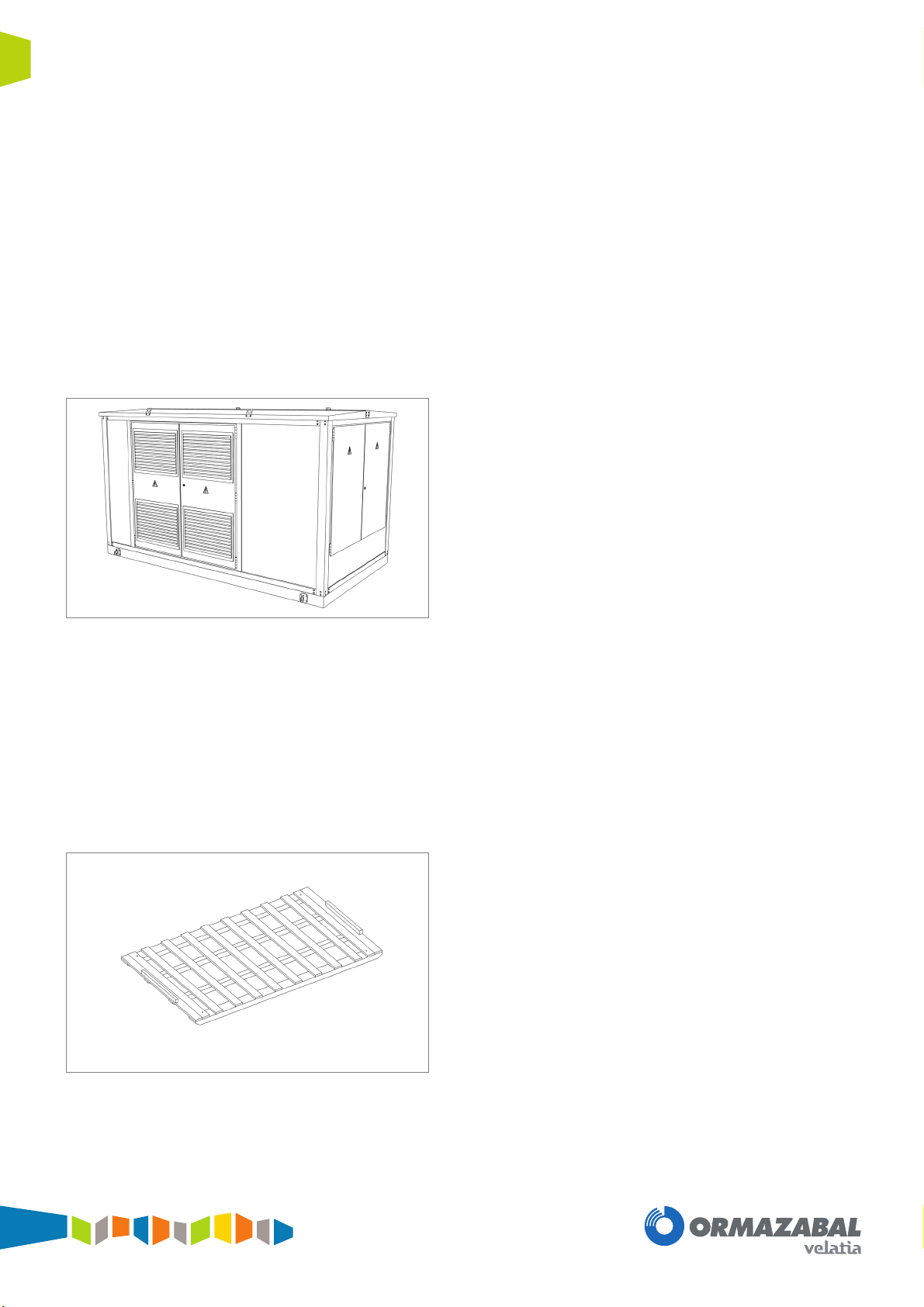
►Base frame manufactured with laminated profiles
UPE 140
►Optionally, an oil collection pit made of galvanised
sheet metal, with a capacity of 600 litres.
►Optionally protective earth disconnection box and
service earth disconnection box can be supplied,
located in the low voltage compartment on the left
and right of the low voltage switchgear.
►Earth circuit, copper conductor cross section
50 mm2.
►Document holder for general instructions relating to
the transformer substation.
►Lighting in the medium voltage, low voltage and
transformer compartments supplied.
►Optionally, emergency lighting of 50 Lm 1h NM,
IP42, IK04 1 x 6W, class II, 230 V 50/60 Hz.
According to standard IEC 60598-2-22.
►Physical separation between the medium voltage
compartment, power transformer and low voltage
compartment.
1Roof of prefabricated substation
2Enclosure of prefabricated substation
2.1 Medium voltage switchgear door
2.2 Power distribution transformer door
2.3 Low voltage switchboard door
2.4 Medium voltage cable inter-connection
2.5 Low voltage cable inter-connection

5
Description and main characteristicsGeneral Instructions
ormaSET-M
IG-199-EN version 03
1.1 Switchgear and control gear
Anchored to the inside of the enclosure is the switchgear,
made up of the following elements:
►Medium voltage (MV) switchgear with full SF6
insulation up to 36 kV, according to IEC 62271-200.
The following models can be installed:
□CGMCOSMOS 12 and 24 kV, 400/630 A.
□CGM.3 36 kV, 400/630 A.
►MV/LV distribution transformer, according to
IEC 60076-1, oil filled and hermetically sealed, fully
equipped with medium voltage solid insulated
bushings up to 1000 kVA 36 kV.
►Low voltage (LV) board, according to IEC 61439-1
with up to 8 outputs for NH 2 size fuses.
►Medium voltage inter-connection: HEPRZ1
3 x 1 x 95/16mm212/20 kV or 18/30 kV Al.
►Low voltage inter-connection: XLPE 3 x 4x 240 mm2
XZ1 0.6/1 kV.

6 Service conditions General Instructions
ormaSET-M
IG-199-EN version 03
2 Service conditions
ormaSET-M prefabricated substation is designed to be
used under normal outdoor service conditions according to
IEC 62271-1.
Inside the enclosure it is assumed that normal indoor
conditions prevail according to IEC 62271-1.
►Medium voltage functional unit:
□IEC 62271-200
►MV / LV transformer functional unit
□IEC 60076 series
►Low voltage functional unit
□IEC 61439 series
Air temperature
►Minimum: - 5 ºC
►Maximum: + 40 ºC
►Average daily value: + 35 ºC
►Maximum average annual temperature: + 20 ºC
Average relative humidity value, measured in a 24 hour
period, must not exceed 95%.
►Vapour Pressure average (1 month) = 22 mbar.
Altitude
The altitude of the place of installation must not exceed
1000 m.
For working conditions that differ from those given or that
are not mentioned in these instructions, it is necessary to
define what they are and to study how they affect the
design.
In the event of special conditions of use, please consult
Ormazabal.
Degree of pollution
The pollution does not exceed pollution level II (medium),
according to Table 1 of IEC 60815.
Solar radiation
Solar radiation up to a level of 1000 W/m2on a clear day at
noon is considered.
Ice coating
The ice coating shall be considered in the range from 1 mm
up to but not exceeding 20 mm.
Wind speed
The wind speed does not exceed 34 m/s.

7
Dimensions and weightsGeneral Instructions
ormaSET-M
IG-199-EN version 03
3 Dimensions and weights
The dimensions and weights of ormaSET-M, including
transformer 1000 kVA, are:
(1) Compact assembly CGMCOSMOS-2LP and CGM.3-2LP.
Fig. 3.1: Dimensions of ormaSET-M
MODEL ormaSET-M
Height on level zero [mm] 2301
Length [mm] 3936
Depth [mm] 2126
24 kV Weights [kg]
Empty
Enclosure Cover LVB MV
Switchgear(1) Transformer
1000 kVA TOTAL
ormaSET-M 2100 150 310 2400 4960
36 kV Weights [kg]
Empty
Enclosure Cover LVB MV
Switchgear (1)
Transformer
1000 kVA TOTAL
ormaSET-M 2100 150 487 2500 5237
ATransformer side gap (1900 mm)
BTransformer side gap (1940 mm)
CTransformer top space (1930 mm)
DTransformer top space (1890 mm)

8 Transport General Instructions
ormaSET-M
IG-199-EN version 03
4 Transport
4.1 Road transport
During transport ormaSET-M must be firmly fixed to the truck
by the four lifting devices provided on the base frame. Two
transport support beams (20 mm height x 100 mm width x
2000 mm length) must be placed under ormaSET-M at the
partition walls.
Two straps must be placed on the four lifting devices on
the roof with covers to avoid damage during transport.
Fig. 4.1: ormaSET-M
4.2 Sea transport
ormaSET-M can be transported completely assembled in a
standard High Cube (HC) 40” feet container. In order to
prevent damage to the transformer substation, it is
recommended to take into account:
1) A container sea transport wooden base must be
placed under ormaSET-M and fixed to it by four
screws placed on the corners of ormaSET-M base
frame.
Fig. 4.2: Container sea transport wooden base
2) Once ormaSET-M is in the container, will be
secured by straps or airbags to immobilize it on the
base.
3) The two lifting points of figure 5.3 must be placed on
the front of the base frame in order to permit the
extraction out of the container.
4) ormaSET-M must be wrapped in aluminum
vacuum-packed covers (MIL-B-131-H). Dehydrating
salts must be placed inside. After air is removed the
thermal-sealed covers must be sealed.
4.3 Packing
ormaSET-M is delivered unpacked from the factory as
standard. If sea transport is required, protective measures
such as wooden corners, plastic films and covered
ventilation openings must be demanded. These must be
removed on-site before installation.

9
InstallationGeneral Instructions
ormaSET-M
IG-199-EN version 03
5 Installation
When installing ormaSET-M on-site, local building
regulations must be followed. Instructions given in this
general instructions document must be taken into account.
The pressure exerted on the ground by ormaSET-M and its
switchgear and transformers, must not exceed 0.1 kg/cm2.
5.1 Location
The site location should be precisely defined, indicating the
levels of alignment and height of the reference points, such
as: roads, kerbs, milestones, fences, pavilions, pylons, etc.
On the location sketch or drawing, mark out the spaces
available for the crane and the transport truck.
The existence of any circumstance or object that could
impede or obstruct the smooth operation of the installation
must be indicated (posts, cables, ditches, walls, pipelines,
etc.), marking their positions on the drawing with the
corresponding measurements.
Attached is a table of values for the different crane powers,
taking into consideration that these are provided as a guide
and that it is necessary to confirm each case with
Ormazabal.
Fig. 5.1: Unloading operation
5.2 Planning
On the location sketch or drawing, mark out the spaces
available for the crane and the transport truck.
The existence of any circumstance or object that could
impede or obstruct the smooth operation of the installation
must be indicated (posts, cables, ditches, walls, pipelines,
etc.), marking their positions on the drawing with the
corresponding measurements.
Attached is a table of values for the different crane powers,
taking into consideration that these are provided as a guide
and that it is necessary to confirm each case with
Ormazabal.
MAXIMUM DISTANCE "D" FOR SELF-PROPELLED
CRANE, ormaSET-M - 36 kV
(*)The rated power is in t at 3 m
(**) Weight with transformer of 1000 kV
MAXIMUM DISTANCE "D" FOR TOW-TRUCK,
ormaSET-M - 36 kV
(*)The rated power is in t at 1 m
(**) Weight with transformer of 1000 kV
5.3 Preparing the ground
Ormazabal recommends the installation of a concrete slab
cast on-site. ormaSET-M must be firmly fixed to the
concrete slab by four M12 screws placed on the corners of
the base frame. The concrete slab must have medium
voltage and low voltage cable entries.
Fig. 5.2: Recommended concrete foundation
AExcavation
2Crane
MODEL WEIGHT**
[t]
POWER RATING OF THE CRANES*
30 45 50 60 70 80
ormaSET-M 5.2 17 m 25 m 28 m 34 m 40 m 45 m
MODEL WEIGHT**
[t]
POWER RATING OF THE CRANES*
16,5 21,9 26 35 47 58
ormaSET-M 5.2 3 m 4 m 5 m 6 m 9 m 11 m

10 Installation General Instructions
ormaSET-M
IG-199-EN version 03
►Grounds at Risk of Flooding
In this case, the base of ormaSET-M should be
raised 100 mm above the predicted flood level.
5.4 Handling
ormaSET-M has four lifting points on the base with a
diameter of 60 mm, which enable correct handling with a
lifting beam (ref. 395204-06), slings and properly hooking
them for the purpose of guaranteeing a balanced hoisting.
Longitudinal levelling is performed using slings or double
chain leg adjustable slings with safety hooks. The lifting
beam should be anchored directly from the bottom of the
sling. In the event of using "WITH RING", the anchoring is
performed using the ring to lengthen the two branches from
the side of the lifting beam.
Fig. 5.3: Lifting process for ormaSET-M
For transversal balancing, the lifting beam has a series of
numbered holes at its end.
5.5 Cable access and sealing
Optionally, ormaSET-M can be supplied with a lower
closing system, fitted for accessing cables in the medium
voltage area and the low voltage area.
The transformer substation has three cables inputs in the
medium voltage compartment, each one up to a single
cable diameter of 90 mm. In the low voltage compartment
there are 8 outgoings, each one up to a single cable
diameter of 90 mm.
Fig. 5.4: Cable access
5.6 Earthing circuit connection
ormaSET-M has a main earthing conductor system
provided to connect to the earth all metallic parts of the
prefabricated substation not belonging to the main and/or
secondary/auxiliary circuits of the equipment. It consists in
a main 50 mm2cooper earthing conductor on which each
component is connected through a single circuit.
Fig. 5.5: Earthing circuit connection
DANGER
For safety reasons, it is not allowed to carry out any
other type of handling. AMedium voltage cubicles earthing (length: 4100 mm)
BMedium voltage cables earthing (length: 2630 mm)
CTransf. doors earthing (length: 240 mm)
DTransf. doors earthing (length: 240 mm)
ETransf. earthing (length: 2150 mm)
FLVB earthing (length: 850 mm)
GLow voltage doors earthing (length: 315 mm)
HMedium voltage doors earthing (length: 315 mm)
IMedium voltage doors earthing (length: 315 mm)
JTransf. doors earthing (length: 240 mm)
KTransf. doors earthing (length: 240 mm)
LLow voltage doors earthing (length: 315 mm)

11
InstallationGeneral Instructions
ormaSET-M
IG-199-EN version 03
5.6.1 Earth Circuit
A main earthing conductor system is provided to connect to
the earth all components of the prefabricated substation:
►The enclosure of the prefabricated substation.
►The enclosure of the medium-voltage switchgear
and control gear.
►The metal shields and the earthing conductors of
the medium-voltage cables
►The transformer tank.
►The frame and/or enclosure of the low-voltage
switchgear.
►The earthing connection of automatic controls and
remote-control devices.
Optionally this earth circuit can be connected to the
protective earth disconnection box fitted to the inner side of
ormaSET-M Transformer Substation, to the left of the
access door for the low voltage board, using a bare copper
cable with a cross-section of 50 mm2.
The metallic parts of ormaSET-M prefabricated substation
enclosure is designed to carry 30 A (d.c.) from themselves
to the prefabricated substation main earthing point, with a
voltage drop of maximum 3 V. Installer or final user shall
provide adequate earthing measures around the
prefabricated substation in order to prevent dangerous
touch and step voltages.
The torques to be observed are as follows:
Fig. 5.6: Disconnection protection box
5.6.2 Service Earth (Neutral)
Optionally, an earthing feeder (neutral) can be supplied
that connects the neutral busbar of the distribution
transformer to the disconnection box fitted on the right side
of the low voltage compartment.
This connection is made using an insulated copper cable of
0.6/1 kV with a cross-section of 50 mm2.
Fig. 5.7: Neutral disconnection box
METRIC
TORQUE [Nm]
Steel
8.8 Stainless steel A2
M8 21
M10 38
M12 60

12 Replacement electrical equipment General Instructions
ormaSET-M
IG-199-EN version 03
6 Replacement electrical equipment
6.1 Medium voltaje switchgears and
low voltage switchboard
substitution
To replace the electrical equipment inside ormaSET-M,
follow the next procedure:
1) Remove power supply in the medium voltage and
low voltage incomings to ormaSET-M transformer
substation. Follow the electric utility company
procedure and the local electrical safety
regulations.
2) Open the doors to access the medium voltage (MV)
and low voltage (LV) areas.
3) Remove the medium voltage cable incomings and
the low voltage outgoings as indicated in the
general instructions of the corresponding
equipment.
4) Disconnect the earth connections of the equipment
to the earth circuit of the substation, using a 13 mm
spanner.
5) Remove equipment as indicated in the
corresponding equipment general instructions.
6) In order to recommission ormaSET-M transformer
substation, the above procedures must be carried
out in inverse order.
6.2 Transformer substitution
To replace the transformer, follow the procedure below:
1) Remove power supply in the medium voltage and
low voltage incomings to ormaSET-M transformer
substation. Follow the electric utility company
procedure and the local electrical safety
regulations.
2) Open the doors to access the transformer area.
both sides are accessible.
3) Unscrew the fixing points of the transformer to the
enclosure. Use a 13 mm spanner.
4) Remove the medium voltage cable incomings and
the low voltage outgoings of the transformer as
indicated in the general instructions of the
corresponding equipment.
5) Disconnect the earth connections of the equipment
to the earth circuit of the substation, using a 13 mm
spanner.
6) Remove the transformer through the door as
indicated in the general instructions of the
corresponding equipment.
7) In order to recommission ormaSET-M Transformer
Substation, the above procedures must be carried
out in inverse order.

13
OperationGeneral Instructions
ormaSET-M
IG-199-EN version 03
7 Operation
Clean the substation of all dirt from the storage, transport
and installation. If the paint has been damaged, it must be
repaired according to Ormazabal instructions. Please
contact Ormazabal.

14 Substation maintenance General Instructions
ormaSET-M
IG-199-EN version 03
8 Substation maintenance
The substation must be fully maintained according to local
regulations. When performing maintenance, local electric
safety regulations must be taken into account.
Maintenance actions generally include cleaning and
inspection of the equipment. Maintenance procedures of
the equipment must be fulfilled according to the general
instructions of the manufacturer.


Subject to changes
without prior notice.
For more information,
contact Ormazabal
Ormazabal
Distribución Secundaria
IGORRE
Spain
www.ormazabal.com
Table of contents
Other Velatia Enclosure manuals
Popular Enclosure manuals by other brands

Win4NET
Win4NET WinTera-1000 manual

AirClean systems
AirClean systems POWDERSAFE AC794BE Operator's manual

Eaton
Eaton Box 1 Instructions and operation

Safe-t-Cover
Safe-t-Cover 1000 Series Assembly instructions

Phanteks
Phanteks Enthoo Evoly series user manual

Icy Box
Icy Box IB-235-U3 Quick installation guide