Velká Bíteš Turbojet Engine TJ20A User manual

PP-42A
OPERATION AND MAINTENANCE MANUAL
GUARANTEE CERTIFICATE
TURBOJET ENGINE TJ20A
První brněnská strojírna Velká Bíteš, a.s.
December 2014

PP-42A
2
CONTENTS OF TECHNICAL SPECIFICATION
1. SAFETY INSTRUCTIONS.....................................................................................................3
1.1 Definition....................................................................................................................................3
1.2 General safety provision.............................................................................................................3
1.3 Safety warning............................................................................................................................4
1.4 Warning ......................................................................................................................................5
1.5 Guarantee....................................................................................................................................6
2. TECHNICAL PARAMETERS...............................................................................................7
2.1 Technical parameters..................................................................................................................7
3. DESCRIPTION.........................................................................................................................9
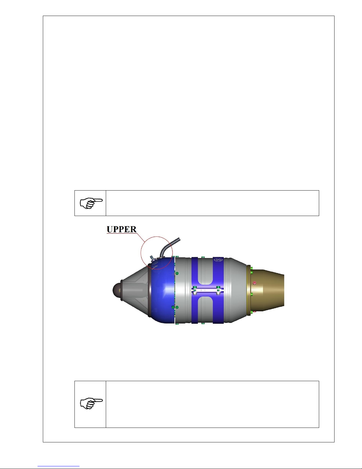
3.1 Description of engine..................................................................................................................9
3.2 Wiring of harness........................................................................................................................9
3.3 Connect of fuel supply................................................................................................................9
3.4 Starting instructions..................................................................................................................10
3.5 Connection scheme...................................................................................................................11
3.6 Recommended accessories .......................................................................................................13
4. EDT STATUS DISPLAY (ENGINE DATA TERMINAL) ................................................14
Menu A –Control Unit Modes ..........................................................................................................15
Menu B - Data....................................................................................................................................15
5. MAINTENANCE OF ENGINE ............................................................................................28
5.1 Check-up of rotating parts ........................................................................................................28
5.2 State of fuel filter pollution.......................................................................................................28
5.3 Stocking instructions.................................................................................................................28
6. CONTENT OF ENGINE IS PACKAGE..............................................................................28
7. EXHAUST PIPE FOR THE TJ20A TURBOJET ENGINE ..............................................29
8. TURBOJET ENGINE TJ20A DIMENSIONAL DRAWING............................................30

PP-42A
3
1. SAFETY INSTRUCTIONS
1.1 Definition
In this manual relevant steps are preceded by WARNINGS or CAUTIONS. For WARNINGS
and CAUTIONS contained at this manual apply these definitions:
1.1.1 Warning
Caution!
Operating procedures or maintenances jobs, methods, circumstances or
instructions, whose non-observance could cause injury or death of personnel
or can cause long-time health hazard.
Caution!
This symbol warns of hot objects and surfaces.
Any violation of the corresponding restrictions may affect the health of the
user.
Attention!
Fire or explosion hazard!
1.1.2 Caution
Operating procedures or maintenance jobs, methods, circumstances or
instructions, which non-observance could cause damage or destruction of
equipment.
1.2 General safety provision
Following the description of general safety provision, which does not relate to any specific
activity and therefore is not mentioned in other parts of this manual. This is general
recommendation, which should be understand and observed by the maintenance personnel in
course of relevant phases of operation and maintenance.

PP-42A
4
1.3 Safety warning
The operator of turbojet engine TJ20A (below only engine) must during engine testing
and operation take into account the following safety risks:
a) Aspiration of foreign objects
The engine needs a large amount of air for its function, which may result in
suction of foreign objects in the space of the compressor inlet, if are not
fixed sufficiently. You must remove all free objects near of suction chamber
(sweat rag, screws, nut, harness and other materials) before starting of this
engine. Before first starting of model with this engine you must check that
no free object is at suction chamber as chippings, screws or some metal
turnings from production of model. This object can damage the turbine.
b) Single-direction thrust
The engine generates more than tenfold axial thrust in relations to its own
weight, during test it must be fixed sufficiently against movement.
c) Exhaust gas temperature
Never look to the output nozzle and never touch it by hands. Exhaust gases
exit the engine with high speed achieve at nozzle temperature up to 780 °C.
The operator must take necessary precautions against risk of fire.
d) Noise level
Operating of this engine causes high noise level. You must use appropriate
sound protection facilities.
e) Lubrication
This engine has not its lubricating system. Bearings of this engine are
lubricating by fuel where must be add 3 % of turbine oil.
Fully synthetic oils for two-stroke engines are not suitable and must not be
used.
f) Fuel cleanness
The operator must guarantee to be into engine fuel system supply fuel
without any impurities.
g) Law-abidingness
Inquire about law-abidingness concerning operation of this kind of engine.
Please, make sure that you will comply all law of country where will be
operate this engine.

PP-42A
5
h) Dangerous zone
For safety reason a presence of persons is forbidden in the zone of radius
R1= 12 m on sides and behind the engine in the zone of radius R2=1 m.
Operator can be at these zone only with sound protection facilities.
You are responsible for the protection of people against injury. When
operating the model, maintain safety distance of 1.5 km from populated
areas to protect persons, animals and property. Maintain safe distance from
overhead lines. Don't fly the model in bad weather, especially in case of
low-level clouds and fog. Never fly directly against the sun as you may lose
visual contact with the model. To prevent collision with a real aircraft,
whether manned or unmanned, immediately land the model, if such aircraft
gets near.
1.4 Warning
Turbojet engine TJ20A was designed purely for using inside aircraft model
and it is not suitable for any other purpose. Never use this turbojet engine
for persons, object or vehicles, only for well designed model of aircraft,
every other using can cause hurt or death.
Any deviation from specifications of this manual, using of uncertified parts,
materials, systems design modification or setting can have negative effect for
function and safety of this engine.
You can not operate this engine without presence or assistance of other
person, which can undertake assistance anytime.
PBS Velká Bíteš, a.s. cannot control observation of this manual for operation and
maintenance or installation, operation, using and maintenance of this engine. This is the
reason, why PBS Velká Bíteš, a.s. has not responsibility for losses, claims or costs cause
by wrong using and operation of this engine.
Operation of this engine can be realize purely for own risk of operating person!

PP-42A
6
1.5 Guarantee
The guarantee relating purely to positive manufacturing or material defects arise during the
guarantee period. Any other claims are eliminated. All costs regarding packing and transport
will pay the seller. We will not guarantee waste during the transport. The guarantee is with no
validity when is defect of the product caused by some accident, bad operating or modification
of this product.
Serial number of engine ………………………………………… guarantee 2 years
Date …………………………

PP-42A
7
2. TECHNICAL PARAMETERS
2.1 Technical parameters
* hold for standard conditions t0= 15°C, p0= 101,325 kPa, v0= 0 km/hod
*Max. thrust
[N]
200
5
5
Max. outsider diameter
[mm]
121
Length including starter
[mm]
315±1
Engine weight
(without battery)
[kg]
< 2,2
Range of operating speed
[RPM]
35 000 ÷ 122 000
Compressor
radial
*compressor compression k
[-]
3,5
*intake air quantity
[kg/sec]
0,4
*SFC at max. trust
[kg/Nh]
0,165
Fuel consumption at idle
ml/min
126,6
Maximal fuel consuption
ml/min
650,0
Fuel
Jet A1 or equivalent + 3 % turbine oil
Cleanness of fuel must match to class
10-11 according GOST 17216-71 or 7-8
according NAS 1638.
Turbine
axial
*Temperature of intake air
[°C]
max. 780
Bearings
hybrid (lubricated by fuel)
Supply voltage rating
[V]
12 V DC (insulated from ground)
Operating range of outdoor
temperature
[°C]
-20 °C ÷ + 50 °C
Flight speed range
[M]
0 ÷ 0,6
Altitude range
[m AMSL]
0 ÷ 6000
2.1.1 Sensor of this engine:
- temperature of intake air t11x TC1047A
- temperature of output air t31x thermocouple kind K
- engine speed 1x Hall sensor
2.1.2 Inside fittings of this engine:
a).electronic board containing circuits for measure and control function
b).booster with break-in clutch (SE)
c).electro valve for fuel starting circuit (SV)
d).electro valve for operation fuel circuit (FV)
e).heating pencil 11,4 V
f). fuel pump

PP-42A
8
2.1.3 Connection of engine with control electronic
See picture at clause 3.5
2.1.4 Accessories of this engine which is delivery separately:
-Fuel filter fuel input to hose Js 4
fuel output to hose Js 4
-Engine Data Terminal
-Hose D6,5 0,4 m
-Engine clamp optional accessories
-Suction screen optional accessories
2.1.5 Time to overhaul:
-total operation time 50 hours or 500 starts, whichever happens first
2.1.6 Connection dimensions of TJ20A engine
According to customer’s request the TJ 20A engine can be supplied with optional vertical or
horizontal clamp for its fixation.
Connection dimensions of TJ20A engine are mentioned at clause 8.
This engine must be installed in model with fuel supply with up direction,
swing from vertical axe of model can be ±5°.
2.1.7 Required parameters of power supply
Battery 12 V/ 2500 mAh, or 3 Li-Pol battery cell can ensure power supply of this engine.
The battery must be able provide 30A during start of the engine.
The breaker connected downstream the battery must be rated for 30 A.
Ensure the battery is optimally charged to provide enough power for the
start of the turbine, which is very demanding.
Electronic system of engine aborts starting sequence for safety reasons of
engine during flight if voltage drops under 10 V during start.
Also keep in mind that the full battery capacity is not available at low
temperatures, especially when using a LiPol battery.

PP-42A
9
Caution!
The battery must be disconnected from the model during charging.
Attention!
Fire hazard! Li-Pol type batteries can explode if charging parameters are set
incorrectly. Always observe the instructions provided by the manufacturer of
the charger. When charging, the batteries must be under constant
supervision.
CAUTION
Supply voltage of 4,8V from the engine is brought on red wire of RC connector.
For example this supply voltage can be used as power supply of control. Maximal
current drain from the engine is 0,3 A. In case you do not need this additional supply
voltage, don´t wire it!!!!
3. DESCRIPTION
3.1 Description of engine
Turbojet engine TJ20A is single-shaft engine with single-stage radial compressor, annular
combustion chamber, single-stage axial turbine and output nozzle.
At the compressor suction is located booster with break-in clutch enabling starting of this
engine from the cockpit net.
Induced air is compressed at radial compressor wheel, pass through radial and axial diffuser to
the combustion chamber, where is blend with evaporate fuel at evaporating piping. Hot gases
caused by fuel burning at combustion chamber expand through single-stage axial turbine and
exhale by high gear from output nozzle to the atmosphere and cause the thrust of this engine.
Axial turbine provides gear of the compressor. Rotor of this engine placed at 2 axial bearings
lubricated by fuel. Part of this engine is electronic board, this board process data from speed
sensor, exhaust gas temperature sensor and input air temperature sensor. Operation of this
engine is control by control unit. Control unit will check all connected accessories after
receipt of start direction and run starting of this engine automatically. Control unit take control
of starter, fuel sensor, starting and main fuel valve following data from all sensor. After
finishing of engine running will automatically start aftercooling with cyclical switching of
starter as long as temperature of exhaust gases will not drop below stated value.
Control unit works on the principles of model technology (variable width of pulse 1 –2 ms
with recurrent frequence 50 Hz).
3.2 Wiring of harness
Harness of engine connected according picture at clause No: 3.5.
Attention!
Cable connection to battery must be red wire to +, black wire to -.
Opposite (wrong) connection results in destruction of electronics!!!
3.3 Connect of fuel supply
After installation of engine to the application and harness connection follow fuel insertion.
Connect the fuel pipe from filter to the engine fuel input. See picture at clause No: 3.5.

PP-42A
10
Attention!
Fire hazard! Observe all applicable regulations for the transport and storage of
fuels (kerosene /jet fuel /etc.).
Don't use open fire when mixing fuels with oil or handling the fuels
(refuelling, draining, etc.).
Ensure that the fuel does not spill or leak into the soil.
3.4 Starting instructions
After connection of engine with EDT, RC, fuel supply and power supply must be made record
of control instructions (stop, idle thrust, maximum) send out from superior system (acceptor)
into the engine control unit by the help of setting data terminal (display). It must be fullfiled
the fuel supply pipe and removed air from whole fuel way before the first start. By using
register 55: FUELPUMPING fill the fuel supply. See the filling and after fulfillment stop the
FUEL PUMPING. Do not pump the fuel into the engine.
Engine is ready for using after disconnection of setting data terminal (display).
During start of the engine take attention to keep horizontal position of the engine and fuel
supply at vertical position.

PP-42A
11
3.5 Connection scheme
Input Signal of
RC Control
ORANGE
Input for RC signal from the control
RED
auxiliary power +4,8 VDC for RC Control
BROWN
GND
Engine Data Terminal
EDT
Switch
PC
Connector service
Hose ø 6,5/ø 4
Hose ø 6,5ø 4
Battery
12V 2500 mAh
Filler neck
Falling suction
+
-
Tank Breathing
Connector
core
Connector
pin
20 ms
0,852,1 ms
Emergency Fuel
Tank
Main Fuel Tank
RC
EDT
ORANGE
Data
RED
Power supply +4,8VDC for EDT
BROWN
GND
Fuel filter
neck

PP-42A
12
ENGINE DATA TERMINÁL
BATTERY
FUEL TANK
FUEL FILTER
CONNECTOR OR SWITCH
CONNECTOR PC
ENGINE
THROTTLE
E

PP-42A
13
3.6 Recommended accessories
3.6.1 Suction screen
The engine can be provided with a suction screen to prevent suction of foreign objects into
the compressor.
Put the suction screen on the engine
starter in such way, so that the grooves
on the screen fit onto the protrusions on
the starter. Insert the cotter pin into the
opening in the starter and bend its ends
apart along the starter circumference.
3.6.2 Engine clamp
Vertical engine clamp Horizontal engine clamp

PP-42A
14
4. EDT STATUS DISPLAY (ENGINE DATA TERMINAL)
EDT (Engine Data Terminal)
Control and Monitoring Panel
Main Display:
E
G
T
9
9
9
°
C
T
H
:
1
0
0
%
R
P
M
1
2
0
.
0
U
b
1
2
.
6
V
In the space for RPM and EGT indication, the display will show only physical engine speed
and exhaust gas temperature. All other parameters will be displayed in Menu A or Menu B.
Push-button Functions:
- Menu entering, selection confirmation, menu leaving by pressing the button for
more than 2 s
- Movement in menu, value increasing
- Movement in menu, value decreasing, engine start upon actuating from EDT
EGT a RPM
Menu A
Menu B

PP-42A
15
Menu A –Control Unit Modes
LOCK → Setting upon battery switch-on and after COOL mode
(without RC signal)
STOP → Setting upon battery switch on and after COOL mode
(RC signal set to STOP)
IDLE → RC signal set to IDLE (displayed in idle speed)
TH:100 % → RC signal set from 1 % to 100 % (engine speed within the range from
IDLE to ENGINE N100 %)
COOL → Engine aftercooling mode (aftercooling terminated upon reaching
100 °C EGT)
ERROR → Function failure during engine test, start, or run (error message
displayed in menu 1:INFO → ERROR CODES)
TEST → Starter, fuel valves, fuel pump, and heating pencil testing mode
FIRE → Heating pencil preheating mode
START → Engine starting mode
Menu B - Data
Ub12.6V → Battery voltage
FP 0.0V → Fuel pump effective voltage
ST 0.0A → Starter current
GL 0.0А → Heating pencil current
tin000C → Intake air temperature
r 120.0 → Reduced speed
Procedure of engine actuating by RC input:
1) After switching on power supply and setting RC signals in the R/C SETTINGS menu,
STOP signal must be set at the RC transmitter. The display will indicate STOP in
Menu A.
2) Set IDLE signal at the RC transmitter. The display will indicate IDLE in Menu A.
3) Set 100 % signal at the RC transmitter. The display will indicate ТH: -REL in Menu A
If TH: +RUN is indicated, the whole actuating procedure must be repeated.
4) Within 6 seconds, you must set the RC transmitter signal to IDLE. The device test,
during which the display indicates TEST in Menu A, will follow and, after successful
test, the engine will be started in idle speed. During the engine start, the display
indicates FIRE and START in Menu A and, after reaching idle speed, the display
indicates IDLE in Menu A.
If you fail to set the RC transmitter signal to IDLE within 6 seconds, the engine will
switch to STOP mode and the display will indicate STOP in Menu A. To start the
engine, the whole procedure must be repeated.

PP-42A
16
Menu SETUP:
EGT999°C TH:100%
RPM120.0 Ub12.6V
1: INFO
>>>
2: STATISTICS
>>>
3: LIMITS
>>>
4: R/C-SETTINGS
>>>
5: TEST-DEVICES
>>>
6: RESET-ENGINE
>>>

PP-42A
17
Menu - 1: INFO (only for reading)
10: R/C-FAILS
Number of RC connection fails during the last engine run
11: JET-ENGINE
Engine type and serial number
12: FIRMWARE
Firmware version
13: LIFE-TIME
Maximum time to the engine GO
14: ERROR-CODES
Defects causing engine switch-off or lack of functionality
15: ERROR-STD
Detailed code of failure causing shutdown or non functionality of engine.
16: ERROR-EXT
Detailed code of failure causing shutdown or non functionality of engine.
1: INFO
>>>
10: R/C-FAILS
0
11: JET-ENGINE
TJ20A S/N:0000
12: FIRMWARE
Version v06.16
13: LIFE-TIME
0 hour
14: ERROR-CODES
No Error
15: ERROR-STD
0x00000000
16: ERROR-EXT
0x00000000

PP-42A
18
RC FAILS Loss of RC signal during engine run will set 45:FAILS-THROTTL
speed for the 44:FAILS-TIME period and, after this period lapses, the
engine switches off.
TIME Failure to reach idle speed (IDLE) since the engine start beginning. If
the engine fails to reach IDLE within 60 s after the start, starting is
terminated.
LOW BATT Low battery voltage. Upon battery voltage drop below 10 V in STOP
mode, TEST mode, and START mode, the engine switches off
immediately. Upon battery voltage drop below 9 V in Engine Run mode
and in COOL mode the engine switches off immediately.
HIGH BATT High battery voltage. Upon battery voltage rise over 15 V,the engine
switches off immediately.
BAD STARTER Failure of starter during device test or engine start
BAD GLOW Failure of heater plug during device test or engine start
BAD PUMP Failure of fuel pump during device test or engine start
BAD EGT Failure of exhaust gas temperature sensor during device test or engine
start
MAX EGT High exhaust gas temperature during engine start and run.
Should temperature during engine start exceed the value 39: START-
EGTOFF for a period longer than 3 seconds, the engine switches off.
Should temperature during engine run exceed the value 3A: RUN-
EGT-OFF for a period longer than 3 seconds, the engine switches off.
MIN RPM Speed drop during engine run. Should the engine speed drop bellow
25,000 rpm, the engine switches off.
In device test or engine start modes, it may be caused by starter or
clutch malfunction.
OVER RPM Overspeed during engine run. Should the engine speed rise over
124,000 rpm, the engine switches off.
GENERAL ERROR Electronics malfunction Restart the engine (switch the engine power
supply off and on again) or, if engine restart does not help, reset the
engine (in Menu 6: RESET-ENGINE) back to the factory settings.
If the engine is in modes TEST, FIRE, START (engine start), or COOL (engine
aftercooling), do not perform any operations by means of EDT!!!

PP-42A
19
Menu –2: STATISTICS (only for reading)
2: STATISTICS
>>>
20: RUNS-TOTAL
0
21: START-ABORT
0
22: RUNS-ABORT
0
23: HOUR-METER
000:00´0
24: EGT-AVG/PEAK
0°C/0°C
25: FUELPMP-MIN
0 mV/ 0 mV
26: FUELPMP-MAX
0 mV/ 0 mV
27: RPM-MIN/MAX
0 / 0

PP-42A
20
20: RUNS-TOTAL
Total number of engine starts and runs
21: START-ABORT
Total number of engine failed starts
22: RUNS-ABORT
Total number of engine failed runs
23: HOUR-METER
Total hours worked by the engine (total time of the fuel pump operation)
Units –HH.MM‘SS
24: EGT-AVG/PEAK
Average and maximum exhaust gas temperature during the last engine run
25: FUELPMP-MIN
Effective voltage of the fuel pump in idle speed (IDLE) of the engine during the last and
last but one engine run
26: FUELPMP-MAX
Effective voltage of the fuel pump at 95 % of ENGINE N100 % speed during the last and
last but one engine run
27: RPM-MIN/MAX
Minimum and maximum speed during the last engine run
Table of contents
Popular Engine manuals by other brands

Sumitomo Drive Technologies
Sumitomo Drive Technologies IB Series Maintenance manual

Briggs & Stratton
Briggs & Stratton PROFESSIONAL SERIES 110000 Operator's manual

Flux
Flux FBM-B 3100 Original operating instructions

Polini
Polini THOR 190 HF Use and maintenance manual

MINN KOTA
MINN KOTA TERROVA installation instructions

Iveco
Iveco N67 ENT M45 Use and maintenance