1Manuale d’Uso
MODULO GPS DA ESTERNO
Leggere attentamente tutte le istruzioni
GEO-2 è un modulo GPS che consente di catturare le informazioni di data,
ora e posizione dai satelliti. Queste informazioni possono essere condivise
con i dispositivi Vemer progettati per interfacciarsi con il GEO-2, in modo da
garantire una sincronizzazione sempre perfetta.
Codice Modello Descrizione
VE789900 GEO-2 Modulo GPS da esterno
AVVERTENZE DI SICUREZZA
Durante l’installazione ed il funzionamento del prodotto è necessario rispettare
le seguenti indicazioni:
1) Il prodotto deve essere installato da persona qualificata rispettando
scrupolosamente gli schemi di collegamento.
2) Non alimentare il prodotto se qualche parte risulta danneggiata.
3) Il prodotto deve essere installato e messo in funzione in conformità con la
normativa vigente in materia di impianti elettrici.
4) Non utilizzare il prodotto per scopi diversi da quelli indicati.
5) Il prodotto può essere utilizzato in ambienti con categoria di sovratensione III e
grado di inquinamento 2.
6) Prima di accedere ai morsetti di collegamento sconnettere l’alimentazione
dall’impianto
7) Dopo l’installazione deve essere garantita la inaccessibilità ai morsetti
di collegamento senza l’uso di appositi utensili.
CARATTERISTICHE TECNICHE
• Alimentazione: dai dispositivi Vemer compatibili
• Assorbimento: 30mA massimo
• Installazione da parete o da palo
• Cablaggio
– Sezione cavi flessibili: 0,75 ÷ 1,5 mm2
– Diametro massimo dei cavi con guaina: 8 mm
• Grado di protezione: IP54
• Temperatura di funzionamento: 0 ÷ +50 °C
• Temperatura di immagazzinamento: -10 ÷ +60 °C
• Umidità di funzionamento: 20÷90% non condensante
• Led rosso/verde/arancione per la segnalazione dello stato del dispositivo (Figura 1)
INSTALLAZIONE
• L’installazione può avvenire a parete o a palo (tramite adattatore presente nella
confezione)
• Rimuovere la calotta facendo leva sui dentini posti ai lati del prodotto
• Far passare i cavi attraverso il pressacavo posto sul lato inferiore e collegare i
cavi dell’alimentazione e del bus rispettando lo schema di collegamento (Figura 2)
• Stringere il pressacavo e riposizionare la calotta.
4STATO DISPOSITIVO
• All’accensione il led emette 1 lampeggio di colore rosso come segue:
OFF ON OFF ON
… 1 s 1 s …
• Il lampeggio del led di colore verde indica il numero di satelliti ricevuti:
N° satelliti Sequenza led verde
ON OFF RIPETIZIONI
3 – 5 100 ms 300 ms 3 ogni 5 secondi
6 – 8 100 ms 300 ms 6 ogni 5 secondi
9 – 12 100 ms 300 ms 9 ogni 5 secondi
• L’invio dei dati al dispositivo collegato è segnalato per 3 secondi dal lampeggio
di colore rosso del led come segue:
ON OFF ON OFF …..
100 ms 100 ms 100 ms 100 ms …..
• Il malfunzionamento del dispositivo viene segnalato dal lampeggio
di colore rosso del led come segue:
ON OFF ON OFF …..
500 ms 500 ms 500 ms 500 ms …..
• La mancata ricezione per più di 30 minuti dei dati satellitari necessari ad ottenere una
posizione GPS corretta, causa un riavvio del modulo. Questa condizione è segnalata
per 3 secondi dal lampeggio di colore arancione come segue:
ON OFF ON OFF …..
300 ms 300 ms 300 ms 300 ms …..
1User Manual
GPS MODULE FOR EXTERNAL USE
Read all the instructions carefully
GEO-2 is a GPS module that allows you to capture the information of date,
time and position from satellites. This information may be shared with Vemer
devices designed to interface with GEO-2, so as to ensure a synchronization
always perfect.
Code Model Description
VE789900 GEO-2 GPS module for external use
SAFETY WARNINGS
During product installation and operation it is necessary to observe the
following instructions:
1) The product must be installed by a qualified person, in strict compliance
with the connection diagrams.
2) Do not power the instrument if any part of it is damaged.
3) The product must be installed and activated in compliance with current
electric system standards.
4) Do not use the product for purposes different from the one specified.
5) The product can be used in environments with category of overvoltage III
and pollution degree 2.
6) Before accessing the connection terminals, disconnect the power supply
7) After installation, inaccessibility to the connection terminals without
appropriate tools must be guaranteed.
TECHNICAL CHARACTERISTICS
• Power supply: from compatible Vemer devices
• Absorption: 30mA max (during receiving GPS)
• Wall or pole installation
• Wiring
– Flexible cables section: 0.75 ÷ 1.5 mm2
– Sheathed cables maximum diameter: 8 mm
• Protection degree: IP54
• Operating temperature: 0 ÷ +50 °C
• Storage temperature: -10 ÷ +60 °C
• Operating humidity: 20÷90% non condensing
• Red / green / orange led for signaling device status (Figure 1)
INSTALLATION
• Installation can be wall or pole (by using the adapter in the package)
• Remove the cover by leveraging the teeth on the sides of the product
• Pass the cables through the cable entry on the bottom side and connect the
power and bus cables respecting the wiring diagram (Figure 2)
• Tighten the cable gland and replace the cover.
4DEVICE STATUS
• When you power on the led emits 1 red flash as follows:
OFF ON OFF ON
… 1 s 1 s …
• The flashing of the green led indicates the number of the received satellites:
N° satelliti Sequenza led verde
ON OFF RIPETIZIONI
3 – 5 100 ms 300 ms 3 every 5 seconds
6 – 8 100 ms 300 ms 6 every 5 seconds
9 – 12 100 ms 300 ms 9 every 5 seconds
• Sending data to the connected device is signaled by the red flashing
of the LED for 3 seconds as follows:
ON OFF ON OFF …..
100 ms 100 ms 100 ms 100 ms …..
• The malfunction of the device is signaled by the red flashing of the led as follows:
ON OFF ON OFF …..
500 ms 500 ms 500 ms 500 ms …..
• Failure to receive the satellite data necessary to obtain a correct GPS position
for more than 30 minutes causes a restart of the module. This condition
is signaled by the orange flashing of the led for 3 seconds as follows:
ON OFF ON OFF …..
300 ms 300 ms 300 ms 300 ms …..
ai sensi dell’art. 26 del Decreto Legislativo 14 marzo 2014, n. 49
“Attuazione della direttiva 2012/19/UE
sui rifiuti di apparecchiature elettriche ed elettroniche (RAEE)”
Il simbolo del cassonetto barrato riportato sull’apparecchiatura
o sulla sua confezione indica che il prodotto alla fine
della propria vita utile deve essere raccolto separatamente dagli altri rifiuti.
L’utente dovrà, pertanto, conferire l’apparecchiatura giunta a fine vita
agli idonei centri comunali di raccolta differenziata dei rifiuti elettrotecnici ed elettronici.
In alternativa alla gestione autonoma, è possibile consegnare gratuitamente
l’apparecchiatura che si desidera smaltire al distributore, al momento dell’acquisto
di una nuova apparecchiatura di tipo equivalente.
Presso i distributori di prodotti elettronici con superficie di vendita di almeno 400 m2
è inoltre possibile consegnare gratuitamente, senza obbligo di acquisto,
i prodotti elettronici da smaltire con dimensioni inferiori a 25 cm.
L’adeguata raccolta differenziata per l’avvio successivo dell’apparecchiatura dismessa
al riciclaggio, al trattamento e allo smaltimento ambientalmente compatibile
contribuisce ad evitare possibili effetti negativi sull’ambiente e sulla salute e favorisce
il reimpiego e/o riciclo dei materiali di cui è composta l’apparecchiatura.
Vemer S.p.A.
I - 32032 Feltre (BL) • Via Camp Lonc, 16
e-mail: info@vemer.it - web site: www.vemer.it
V3IS01123-010
Mod. GEO-2
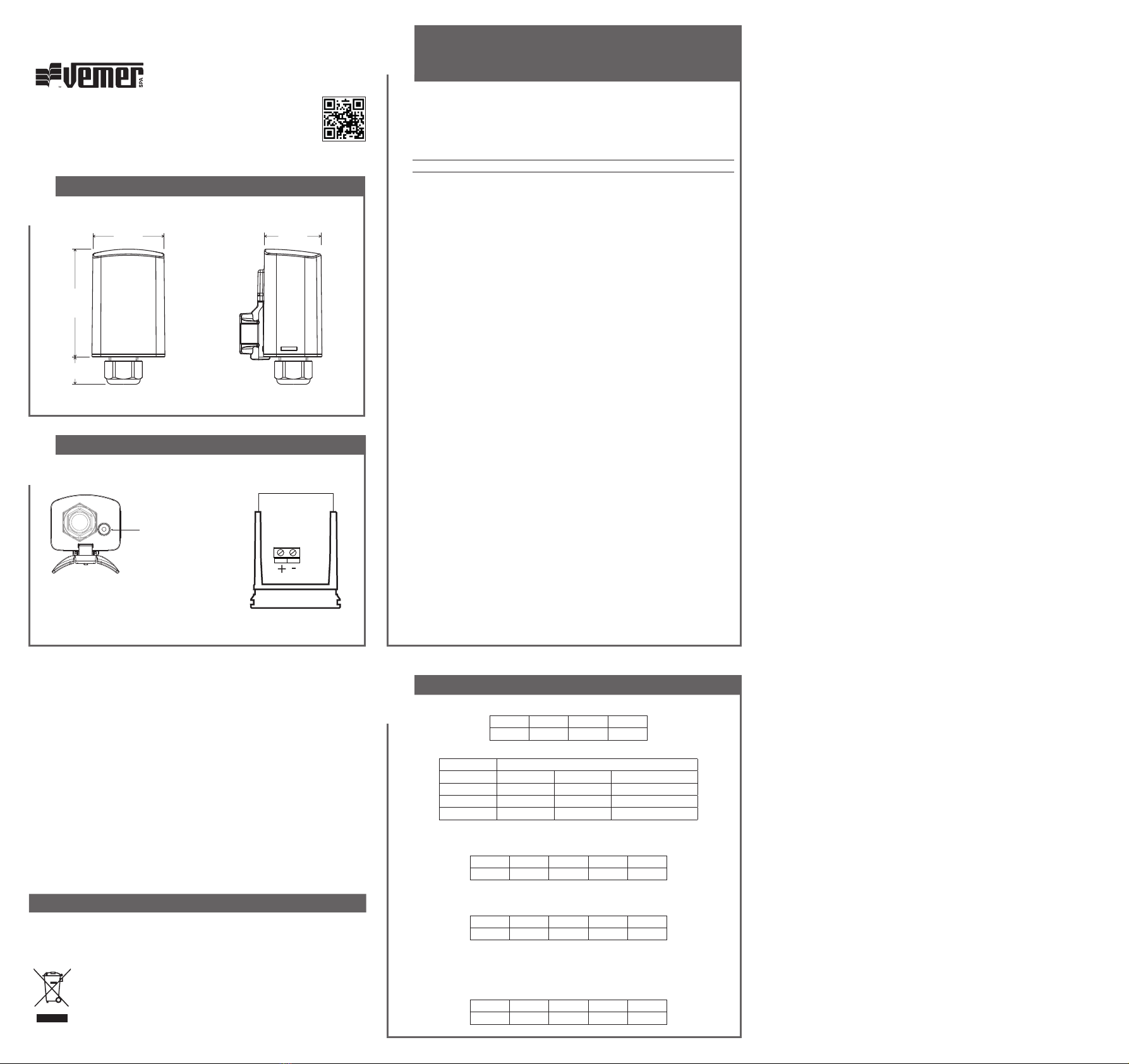
DIMENSIONI / DIMENSIONS
2
79
52
20
41
NORME DI RIFERIMENTO / REFERENCE STANDARDS
La conformità con le Direttive Comunitarie: 2014/53/UE (RED)
è dichiarata in riferimento alle seguenti norme armonizzate: • EN 61010-1
• ETSI EN 301 489-1, ETSI EN 301 489-3, ETSI EN 489-19, ETSI EN 301 511
Compliance with Community Directives: 2014/53/UE (RED)
is declared with reference to the following harmonized standards: • EN 61010-1
• ETSI EN 301 489-1, ETSI EN 301 489-3, ETSI EN 489-19, ETSI EN 301 511
02-2022
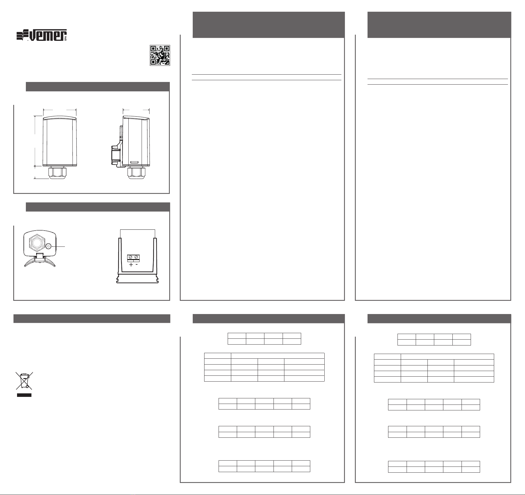
SCHEMI DI COLLEGAMENTO / CONNECTION DIAGRAM
Led per segnalazione
stato dispositivo
Led for signaling
device status
Figura / Figure 1
Figura / Figure 2
3