uSwitch and uSwitchPro Installation and Operating Manual Page 2
Table of Contents
Introduction................................................................................................................................................................3
uSwitch and uSwitchPro Features................................................................................................................................4
Installation Guidelines (Read before Installing) .............................................................................................................6
uSwitch and uSwitchPro Quick Start Guide..............................................................................................................6
About uSwitch ..........................................................................................................................................................8
Power Supply Connection...........................................................................................................................................9
Relay Connection.......................................................................................................................................................9
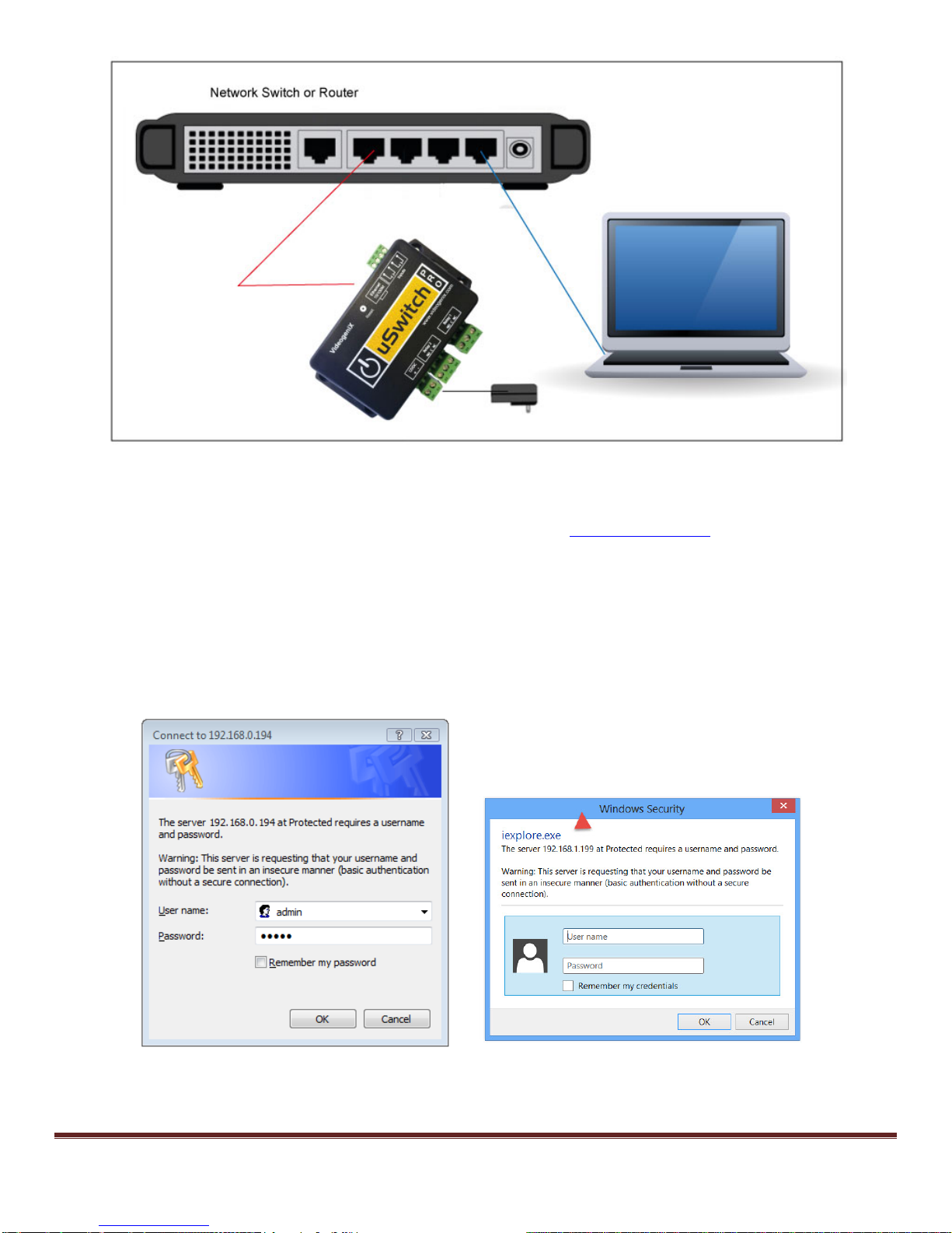
Network Connection....................................................................................................................................................9
Control Center – Home Page.....................................................................................................................................11
Menu Navigation.......................................................................................................................................................12
Control Center (Relay 1- Momentary Mode) ............................................................................................................12
Control Center (Relay1 Watchdog Mode, Startup Delay phase)...................................................................................13
Control Center (Relay1 Watchdog Mode, Ping Delay phase).......................................................................................15
................................................................................................................................................................................15
Control Center (Relay1 Watchdog Mode, pinging phase).............................................................................................16
Control Center (Relay1 Watchdog Mode, auto reboot countdown phase) .....................................................................17
Control Center (GPIO1 with counter enabled).............................................................................................................18
Network Configuration Page......................................................................................................................................19
Relay Configuration Page..........................................................................................................................................22
Force Watchdog Reboot ...........................................................................................................................................24
GPIO Configuration Page (uSwitchPro only)...............................................................................................................26
Watchdog Configuration Page................................................................................................................................27
Virtual Relay Configuration Page............................................................................................................................29
Authorization Configuration Page...............................................................................................................................31
Security Notes..........................................................................................................................................................31
uSwitch/uSwitchPro Board Schematic........................................................................................................................32
Access Control to Electronic Door Strike....................................................................................................................33
Driving multiple uSwitch Relays from a single uSwitch GPIO or Virtual Button.....................................................33
Connecting to High Power devices (such as Motors, etc).............................................................................................34