Videotec geko irn User manual

ENGLISHITALIANOFRANÇAISDEUTSCH
EN
English - Instructions manual
IT
Italiano - Manuale di istruzioni
FR
Français - Manuel d’instructions
DE
Deutsch - Bedienungslanleitung
GEKO IRN
LED illuminator


EN
English - Instructions manual
ENGLISH
GEKO IRN
LED illuminator

Contents ENGLISH
1 About this manual ......................................................................................................... 3
1.1 Typographical conventions.................................................................................................................................. 3
2 Notes on copyright and information on trademarks.................................................. 3
3 Safety rules..................................................................................................................... 3
4 Identication.................................................................................................................. 5
4.1 Product description and type designation..................................................................................................... 5
4.2 Product markings .................................................................................................................................................... 5
5 Preparing the product for use ...................................................................................... 6
5.1 Unpacking and contents....................................................................................................................................... 6
5.1.1 Unpacking.................................................................................................................................................................................. 6
5.1.2 Contents...................................................................................................................................................................................... 6
5.2 Safely disposing of packaging material........................................................................................................... 6
6 Assembling and installing ............................................................................................ 6
6.1 Assembly..................................................................................................................................................................... 6
6.2 Installation.................................................................................................................................................................. 6
6.2.1 Installation of wall-mounted illuminator........................................................................................................................ 6
6.2.2 Description of connection cables...................................................................................................................................... 7
6.2.2.1 Power supply cable version 12Vdc, 24Vdc, and 24Vac.................................................................................................................... 7
6.2.2.2 Power supply cable version from 100Vac to 240Vac........................................................................................................................ 8
6.2.2.3 Control cable.................................................................................................................................................................................................. 8
6.2.3 Cable technical specications............................................................................................................................................. 9
6.2.4 LED illuminator switching on threshold adjustment ................................................................................................. 9
6.2.4.1 Twilight sensor activation threshold adjustment ............................................................................................................................. 9
6.2.4.2 Disabling the twilight sensor..................................................................................................................................................................10
6.2.5 LED illuminator power adjustment.................................................................................................................................10
6.3 Operational test......................................................................................................................................................10
6.3.1 Check operation of the twilight sensor.........................................................................................................................10
7 Disposal of waste materials........................................................................................ 11
8 Technical data .............................................................................................................. 11
8.1 General ......................................................................................................................................................................11
8.2 Mechanical...............................................................................................................................................................11
8.3 Electrical....................................................................................................................................................................11
8.4 Illuminators..............................................................................................................................................................11
8.5 Environment............................................................................................................................................................11
8.6 Certications ...........................................................................................................................................................11
9 Technical drawings ...................................................................................................... 12

Instructions manual - English - EN
3MNVCIRN_1420_EN
1 About this manual
Before installing and using this unit, please read this
manual carefully. Be sure to keep it handy for later
reference.
1.1 Typographical conventions
DANGER!
High level hazard.
Risk of electric shock. Disconnect the
power supply before proceeding with any
operation, unless indicated otherwise.
DANGER!
Hot surface.
Avoid contact. Surfaces are hot and may
cause personal injury if touched.
DANGER!
Emission of visible light or infrared.
It can be harmful for eyes. Pay attention to
the provided indications.
CAUTION!
Medium level hazard.
This operation is very important for the
system to function properly. Please read
the procedure described very carefully and
carry it out as instructed.
INFO
Description of system specications.
We recommend reading this part carefully
in order to understand the subsequent
stages.
2 Notes on copyright and
information on trademarks
The quoted names of products or companies are
trademarks or registered trademarks.
3 Safety rules
Do not stare at the lamp when on. It can be
harmful for eyes.
The infrared LED illuminator emits high-
intensity visible light. In compliance
with standard EN62471/IEC62471, the
photobiological safety assessment has
classied the device in Risk Group 2, where
it exceeds the values of the Exempt Group.
The risk linked to the observer depends
on how the product has been installed
and is used. For installation, follow the
instructions in this manual. Do not open
the illuminator for whatever reason. Do not
look directly at the illuminator using optical
lenses. Exposure hazard values (EHV):
88.1s. Hazard distance (HD): 200mm.
Fig. 1 Infrared illuminator.
RISK GROUP 2
CAUTION: IR emitted
from this product.
Avoid eye exposure.
Use appropriate
shielding or eye
protection.
ATTENTION: IR sont
émis par ce produit.
Éviter toute exposition
des yeux. Utiliser un
blindage approprié ou
une protection oculaire.
GROUPE DE RISQUE 2

EN - English - Instructions manual
4 MNVCIRN_1420_EN
The white light LED illuminator emits
high-intensity visible light. In compliance
with standard EN62471/IEC62471, the
photobiological safety assessment has
classied the device in Risk Group 2, where
it exceeds the values of the Exempt Group.
The risk linked to the observer depends
on how the product has been installed
and is used. For installation, follow the
instructions in this manual. Do not open
the illuminator for whatever reason. Do not
look directly at the illuminator using optical
lenses. Exposure hazard values (EHV):
20.8s. Hazard distance (HD): 200mm.
Fig. 2 White light illuminator.
During normal operation the surface of the
illuminator can reach high temperatures.
Do not allow direct contact and position
the appliance where it is inaccessible to
unauthorised persons. Before touching
switch o the illuminator and allow to cool
for a minimum period of 10 minutes.
• The manufacturer declines all responsibility
for any damage caused by an improper use
of the appliances mentioned in this manual.
Furthermore, the manufacturer reserves the right
to modify its contents without any prior notice.
The documentation contained in this manual has
been collected with great care, the manufacturer,
however, cannot take any liability for its use. The
same thing can be said for any person or company
involved in the creation and production of this
manual.
RISK GROUP 2
CAUTION: Possibly
hazardous optical radiation
emitted from this product.
Do not stare at operating
lamp. May be harmful to
the eye.
ATTENTION:
Des
rayonnements optiques
dangereux peuvent être émis
par ce produit. Ne pas regarder
la lampe directement. Peut
être dangereux pour les yeux.
GROUPE DE RISQUE 2
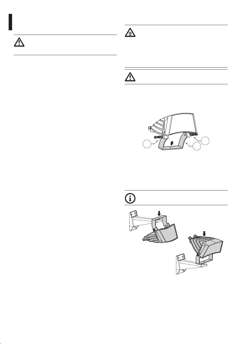
CAUTION! The device must be installed
only and exclusively by qualied technical
personnel.
• Before starting any operation, make sure the
power supply is disconnected.
• Do not use cables that seem worn or old.
• Never, under any circumstances, make any
changes or connections that are not shown in
this handbook. Improper use of the appliance
can cause serious hazards, risking the safety of
personnel and of the installation.
• Use only original spare parts. Non-original spare
parts could cause re, electrical discharge or other
hazards.
• Before proceeding with installation check the
supplied material to make sure it corresponds
to the order specication by examining the
identication labels (4.2 Product markings, page 5).
• A disconnecting device, readily and easily
accessible, must be incorporated in the electrical
system of the building for rapid intervention.
• To connect the power supply line use the
appropriate junction-box (IRNJBUL). For further
information, refer to the product use and
installation manual.

Instructions manual - English - EN
5MNVCIRN_1420_EN
• Installation category (also called Overvoltage
Category) species the level of mains voltage
surges that the equipment will be subjected to.
The category depends upon the location of the
equipment, and on any external surge protection
provided. Equipment in an industrial environment,
directly connected to major feeders/short branch
circuits, is subjected to Installation Category III. If
this is the case, a reduction to Installation Category
II is required. This can be achieved by use of an
insulating transformer with an earthed screen
between primary and secondary, or by tting
listed Surge Protective Devices (SPDs) from live
to neutral and from neutral to earth. Listed SPDs
shall be designed for repeated limiting of transient
voltage surges, suitable rated for operating voltage
and designated as follows: Type 2 (Permanently
connected SPDs intended for installation on the
load side of the service equipment overcurrent
device); Nominal Discharge Current (In) 20kA min.
For example: FERRAZ SHAWMUT, STT2240SPG-
CN, STT2BL240SPG-CN rated 120Vac/240Vac,
(In=20kA). Maximum distance between installation
and reduction is 5m.
• This is a Class A product. In a domestic
environment this product may cause radio
interference. In this case the user may be required
to take adequate measures.
• To comply with the main supply voltage dips and
short interruption requirements, use a suitable
Uninterruptable Power Supply (UPS) to power the
unit.
• In the case of a 24Vac power supply, you must
provide for adequate separation from the AC
power supply line using double or reinforced
insulation between the main power supply line
and the secondary circuit.
4 Identification
4.1 Product description and type
designation
State of the art illuminator, which provides high
reliability and excellent image quality. The GEKO
lights the entire scene evenly, eliminating hotspots
and underexposures, for unbeatable night-time
images and secure surveillance of the area. The high
eciency heat sink body ensures maximum LED
durability and protection against over-temperatures,
whereas the front glass, made of special
technopolymer, provides high infrared transmittance.
The illuminators are protected against electrostatic
discharges.
The illuminator is available in versions 24Vac/12-
24Vdc or 100-240Vac with integrated power supply.
GEKO is supplied with a wall-mount bracket that
rotates horizontally and vertically.
The GEKO infrared illuminator guarantee is 5 years,
while for GEKO with the white light is 2 years.
4.2 Product markings
See the label attached to the product.

EN - English - Instructions manual
6 MNVCIRN_1420_EN
5 Preparing the product for
use
Any change that is not expressly approved
by the manufacturer will invalidate the
guarantee.
5.1 Unpacking and contents
5.1.1 Unpacking
When the product is delivered, make sure that the
package is intact and that there are no signs that it
has been dropped or scratched.
If there are obvious signs of damage, contact the
supplier immediately.
Keep the packaging in case you need to send the
product for repairs.
5.1.2 Contents
Check the contents to make sure they correspond
with the list of materials as below:
• Illuminator with bracket
• Wall-fastening bracket
• Bolts and screws
• Instructions manual
5.2 Safely disposing of packaging
material
The packaging material can all be recycled. The
installer technician will be responsible for separating
the material for disposal, and in any case for
compliance with the legislation in force where the
device is to be used.
When returning a faulty product we recommend
using the original packaging for shipping.
6 Assembling and installing
During normal operation the surface of the
illuminator can reach high temperatures.
Do not allow direct contact and position
the appliance where it is inaccessible to
unauthorised persons. Before touching
switch o the illuminator and allow to cool
for a minimum period of 10 minutes.
The assembly and installation must be
performed only by skilled personnel.
6.1 Assembly
Fasten the top bracket (01) to the illuminator using
the screws and washers (02) supplied.
01
02
02
Fig. 3
6.2 Installation
6.2.1 Installation of wall-mounted
illuminator
The illuminator’s position can be decided at
the time of installation.
Fig. 4

Instructions manual - English - EN
7MNVCIRN_1420_EN
Fasten the bracket as shown in the gure. Drive the
wall screws in tight.
Fig. 5
Fasten the illuminator, complete with its bracket,
using the screw, the nut and the washer supplied.
Fig. 6
Set the illuminator’s vertical and horizontal
inclination by adjusting the two fastening screws.
Fig. 7
Check the resulting illumination range on the screen.
Tighten all the screws.
6.2.2 Description of connection cables
Control cable Power supply
Fig. 812Vdc, 24Vdc and 24Vac version.
Control cable Power supply
Fig. 9From 100Vac to 240Vac version.
6.2.2.1 Power supply cable version 12Vdc,
24Vdc, and 24Vac
The device is Class III. Provide power
supply using a safety transformer or a SELV
continuous current power supply.
The illuminator is provided with a 2m power cable.
Power cables (blue, brown): Connect the two
poles to the supply (24Vac, 50/60Hz or 12-24Vdc). In
case of continuous current power supply, polarity is
irrelevant.
For maximum lengths and recommended cable
sections, refer to the relative chapter (6.2.3 Cable
technical specications, page9).

EN - English - Instructions manual
8 MNVCIRN_1420_EN
6.2.2.2 Power supply cable version from
100Vac to 240Vac
The device is Class I. Connection of the
yellow-green cable to the safety ground
is therefore necessary to ensure electrical
safety.
The illuminator is provided with a 2m power cable.
Power cables (blue, brown, yellow/green): Connect
the brown cable to the phase, the blue one to the
neutral and the yellow-green one to the safety
ground.
For maximum lengths and recommended cable
sections, refer to the relative chapter (6.2.3 Cable
technical specications, page9).
6.2.2.3 Control cable
The product is equipped with a control cable to
manage one input contact and one output contact.
COLORS AND FEATURES OF THE CONTROL CABLE
Cable color Function
Red Input for activation by means of external dry
contact
Green Input for activation by means of external dry
contact
White Dry contact output (Follow)
Black Dry contact output (Follow)
Tab. 1
Input contact: It allows a remote activation of the
illuminator by means of a clean contact placed
between the red and green conductors. For proper
operation, make sure that the twilight sensor is
disabled (6.2.4.2 Disabling the twilight sensor, page
10). The input contact status is the following:
• Open contact input (insulated red and green
poles): Illuminator on.
• Contact closed input (red and green poles in short-
circuit): Illuminator o.
Avoid to use the same external contact
to switch-on or switch-o 2 or more
illuminators.
Input contact
Illuminator 01
Illuminator 01
Illuminator 02
Illuminator 02
Input contact
Input contact
Input contact
Fig. 10
Output contact (Follow): The Follow output has
a clean contact in the white and black poles. The
Follow contact can be used to turn on or o other
illuminators simultaneously in the system or to
verify the camera day/night status. Regardless the
illuminator is activated through the input contact or
the twilight sensor, the output contact status (Follow)
is the following:
• Open contact output (insulated white and black
poles): Illuminator on.
• Contact closed output (white and black poles in
short-circuit): Illuminator o.

Instructions manual - English - EN
9MNVCIRN_1420_EN
6.2.3 Cable technical specications
Depending on the type of illuminator and supply
voltage, comply with the following maximum lengths
for the power cables.
Power supply, 12Vdc
• Voltage drop: 0.6V max.
• Minimum voltage at the power cable input
provided with the illuminator: 11.4Vdc.
CABLES SPECIFICATIONS SUPPLY, 12VDC
Cable sec-
tion
AWG Maximum length
0.75mm² 18 4.5m (14.8ft)
1mm² 17 6.5m (21.3ft)
1.5mm² 16 9m (29.5ft)
2.5mm² 14 15m (49.2ft)
4mm² 10 24m (78.7ft)
Tab. 2
Power supply, 24Vac or 24Vdc
• Voltage drop: 3V max.
• Minimum voltage at the power cable input
provided with the illuminator: 21Vac.
CABLES SPECIFICATIONS SUPPLY, 24VAC OR 24VDC
Cable sec-
tion
AWG Maximum length
0.75mm² 18 35m (114ft)
1mm² 17 50m (164ft)
1.5mm² 16 80m (262ft)
2.5mm² 14 120m (393ft)
4mm² 10 200m (656ft)
Tab. 3
Power supply, from 100Vac to 240Vac
• The cable section is less critical, so no particular
prescription is requested. Ensure the ground
connection is ecient for safety reasons.
• Cable minimum section: 0.75mm² (AWG18).
Control cable
• External command: Red, Green.
• Follow command: White, Black.
• Cable minimum section: 0,34mm² (AWG22).
• Maximum cable length: 200m (656ft).
6.2.4 LED illuminator switching on
threshold adjustment
Adjusting the illuminator trip
threshold
Fig. 11
6.2.4.1 Twilight sensor activation threshold
adjustment
The illuminator has an integrated twilight sensor that
allows its automatic activation and deactivation at
predened luminous conditions.
The twilight sensor is set in the factory at a
predetermined luminous level, suitable for most
installations (approximately 50lx). In the event
the intervention threshold (illuminator activation)
must be adjusted dierently, loosen the plug on
the illuminator rear and proceed adjusting with a
screwdriver.

EN - English - Instructions manual
10 MNVCIRN_1420_EN
By rotating the trimmer clockwise, the night mode
changeover is anticipated (at a greater luminous
value). By rotating the trimmer anti-clockwise,
the night mode changeover is delayed (at a lower
luminous value).
OFF MAX
Fig. 12
Wait for appropriate brightness before switching on
the illuminator. Rotate the trimmer slowly until the
LED on the side of the trimmer switches on. Once the
intervention threshold has been surpassed (LED on),
rotate it slightly in the opposite direction.
After making the adjustments make sure
that the plug is closed tight to ensure
perfect sealing.
6.2.4.2 Disabling the twilight sensor
To deactivate the illuminator from automatically
switching itself on, fully rotate the adjustment
trimmer anticlockwise (end run) (Fig. 12, page10).
This way, switching the illuminator on and o will be
controlled by an external control (switch).
6.2.5 LED illuminator power adjustment
Adjusting the power of the infra-
red illuminators
Fig. 13
Loosen the hermetic plug. Rotate the trimmer,
clockwise to increase the power of the infrared
illuminators and anti-clockwise to decrease it.
MAX POWERMIN POWER
Fig. 14
After making the adjustments make sure
that the plug is closed tight to ensure
perfect sealing.
6.3 Operational test
6.3.1 Check operation of the twilight
sensor
Check operation of the twilight sensor by darkening
it with black tape.

Instructions manual - English - EN
11MNVCIRN_1420_EN
7 Disposal of waste
materials
This symbol mark and recycle system
are applied only to EU countries and not
applied to the countries in the other area of
the world.
Your product is designed and manufactured with
high quality materials and components which can be
recycled and reused.
This symbol means that electrical and electronic
equipment, at their end-of-life, should be disposed of
separately from your household waste.
Please dispose of this equipment at your local
Community waste collection or Recycling centre.
In the European Union there are separate collection
systems for used electrical and electronic products.
8 Technical data
8.1 General
Supplied complete with support
Adjustable built-in twilight sensor for automatic
activation and deactivation
8.2 Mechanical
Die cast aluminium body
Dimensions: 187x251x242mm (7.4x9.9x9.5in)
Unit weight:
• 1.7kg (3.7lb) (from 12Vdc to 24Vdc, 24Vac)
• 2.2kg (4.8lb) (from 100Vac to 240Vac)
8.3 Electrical
Power supply/Current consumption:
• From 12Vdc to 24Vdc, 2.5A max
• 24Vac, 2.5A max, 50/60Hz
• From 100Vac to 240Vac, 1.5A max, 50/60Hz
Power supply voltages permitted tolerance:
• From 120Vac to 230Vac: ±10%
• 24Vac or 24Vdc: ±10%
• 12Vdc: ±5%
Input for activation by means of external dry contact
Dry contact output (Follow)
Multipolar cable L: 2m (6.56ft)
• Control: 4x0.34mm² (AWG22)
• Power supply from 12Vdc to 24Vdc, 24Vac: 2x0.75
mm² (AWG18)
• Power supply from 100Vac to 240Vac: 3x0.75mm²
(AWG18)
8.4 Illuminators
SMD LED
GEKO IRN BEAM PATTERN AND ACHIEVABLE DISTAN
CES FOR ONE ILLUMINATOR
Horizontal
and vertical
beam pat-
terns
Maximum distance
850nm 940nm White light
10˚ 240m (787ft) 140m (460ft) –
30˚ 130m (427ft) 80m (262ft) 120m (393ft)
60˚ 80m (262ft) 60m (197ft) 90m (295ft)
Tab. 4The distances and the performance depend on the
camera/lens used and on the environmental light
conditions.
Achievable distances with camera in Day mode
(colour image)
8.5 Environment
Indoor/Outdoor
Operating temperature: From -40°C (-40°F) to +60°C
(140°F)
8.6 Certications
Electrical safety (CE): EN60950-1
Electromagnetic compatibility (CE):EN50130-4,
EN55022 (Class A), FCC Part 15 (Class A)
Outdoor installation (CE): EN60950-22
Photobiological safety (CE): EN62471
IP protection degree: EN60529 (IP66/IP67)
UL certication: cULus Listed (TYPE 4X) (version with
a white light LED illuminator excluded)

EN - English - Instructions manual
12 MNVCIRN_1420_EN
9 Technical drawings
The dimensions of the drawings are in millimetres.
40
75
12
9
85
116
12
187
134
176
242
111
165
251
116
153
206
35°
80°
80°
9
TWILIGHT SENSOR
SIGNAL
CABLE
LIGHT OUTPUT
REGULATION
POWER LIMIT
REGULATION
POWER SUPPLY
CABLE
Fig. 15 GEKO IRN (from 12Vdc to 24Vdc, 24Vac).

40
75
12
9
85
116
12
9
20°
80°
80°
187
153
242
176
134
116
206
111
132
165
251
SIGNAL
CABLE
LIGHT OUTPUT
REGULATION
POWER LIMIT
REGULATION
CAP
POWER SUPPLY CABLE
TWILIGHT SENSOR
Fig. 16 GEKO IRN (from 100Vac to 240Vac).

MNVCIRN_1420_EN
Headquarters Italy Videotec S.p.A.
Via Friuli, 6 - I-36015 Schio (VI) - Italy
Tel. +39 0445 697411 - Fax +39 0445 697417
Email: [email protected]
France Videotec France S.à.r.l.
Immeuble Le Montreal, 19bis Avenue du Québec, ZA de Courtaboeuf
91140 Villebon sur Yvette - France
Tel. +33 1 60491816 - Fax +33 1 69284736
Email: info.fr@videotec.com
Asia Pacic Videotec (HK) Ltd
Flat 8, 19/F. On Dak Industrial Building, No. 2-6 Wah Sing Street
Kwai Chung, New Territories - Hong Kong
Tel. +852 2333 0601 - Fax +852 2311 0029
Email: info.hk@videotec.com
Americas Videotec Security, Inc.
Gateway Industrial Park, 35 Gateway Drive, Suite 100
Plattsburgh, NY 12901 - U.S.A.
Tel. +1 518 825 0020 - Fax +1 518 825 0025
Email: info.usa@videotec.com - www.videotec.us
www.videotec.com

IT
Italiano - Manuale di istruzioni
ITALIANO
GEKO IRN
Illuminatore a LED

Sommario ITALIANO
1 Informazioni sul presente manuale ............................................................................. 3
1.1 Convenzioni tipograche ..................................................................................................................................... 3
2 Note sul copyright e informazioni sui marchi commerciali........................................ 3
3 Norme di sicurezza ........................................................................................................ 3
4 Identicazione ............................................................................................................... 5
4.1 Descrizione e designazione del prodotto....................................................................................................... 5
4.2 Marcatura del prodotto......................................................................................................................................... 5
5 Preparazione del prodotto per l'utilizzo...................................................................... 6
5.1 Disimballaggio e contenuto ................................................................................................................................ 6
5.1.1 Disimballaggio.......................................................................................................................................................................... 6
5.1.2 Contenuto .................................................................................................................................................................................. 6
5.2 Smaltimento in sicurezza dei materiali di imballaggio.............................................................................. 6
6 Assemblaggio e installazione....................................................................................... 6
6.1 Assemblaggio ........................................................................................................................................................... 6
6.2 Installazione............................................................................................................................................................... 6
6.2.1 Installazione dell'illuminatore a muro.............................................................................................................................. 6
6.2.2 Descrizione dei cavi di collegamento .............................................................................................................................. 7
6.2.2.1 Cavo di alimentazione versione 12Vdc, 24Vdc e 24Vac .................................................................................................................. 7
6.2.2.2 Cavo di alimentazione versione da 100Vac a 240Vac...................................................................................................................... 8
6.2.2.3 Cavo di controllo........................................................................................................................................................................................... 8
6.2.3 Speciche tecniche dei cavi................................................................................................................................................. 9
6.2.4 Regolazione della soglia di accensione degli illuminatori a LED ........................................................................... 9
6.2.4.1 Regolazione della soglia di intervento del sensore crepuscolare............................................................................................... 9
6.2.4.2 Disattivazione del sensore crepuscolare............................................................................................................................................10
6.2.5 Regolazione della potenza degli illuminatori a LED.................................................................................................10
6.3 Verica di funzionamento...................................................................................................................................10
6.3.1 Verica della funzionalità del sensore crepuscolare.................................................................................................10
7 Smaltimento dei riuti................................................................................................ 11
8 Dati tecnici ................................................................................................................... 11
8.1 Generale....................................................................................................................................................................11
8.2 Meccanica.................................................................................................................................................................11
8.3 Elettrico .....................................................................................................................................................................11
8.4 Illuminatori...............................................................................................................................................................11
8.5 Ambiente..................................................................................................................................................................11
8.6 Certicazioni............................................................................................................................................................11
9 Disegni tecnici.............................................................................................................. 12

Manuale di istruzioni - Italiano - IT
3MNVCIRN_1420_IT
1 Informazioni sul presente
manuale
Prima di installare e utilizzare questa unità, leggere
attentamente questo manuale. Conservare questo
manuale a portata di mano come riferimento futuro.
1.1 Convenzioni tipograche
PERICOLO!
Pericolosità elevata.
Rischio di scosse elettriche. Prima di
eseguire qualsiasi operazione assicurarsi di
togliere tensione al prodotto, salvo diversa
indicazione.
PERICOLO!
Supercie calda.
Evitare il contatto. Le superci sono calde
e potrebbero causare danni alla persona in
caso di contatto.
PERICOLO!
Emissione di luce visibile o infrarossa.
Può essere dannoso per gli occhi. Prestare
attenzione alle indicazioni fornite.
ATTENZIONE!
Pericolosità media.
L'operazione è molto importante per il
corretto funzionamento del sistema. Si
prega di leggere attentamente la procedura
indicata e di eseguirla secondo le modalità
previste.
INFO
Descrizione delle caratteristiche del
sistema.
Si consiglia di leggere attentamente per
comprendere le fasi successive.
2 Note sul copyright e
informazioni sui marchi
commerciali
I nomi di prodotto o di aziende citati sono marchi
commerciali o marchi commerciali registrati
appartenenti alle rispettive società.
3 Norme di sicurezza
Non ssare la lampada in funzione. Può
essere dannoso per gli occhi.
L’illuminatore a LED a luce infrarossa
emette luce ad alta intensità visibile. La
valutazione foto-biologica di sicurezza,
in accordo con la norma EN62471/
IEC62471, ha portato alla classicazione del
dispositivo nel Gruppo di Rischio 2, dove
si superano i valori del Gruppo Esente. Il
rischio correlato all’osservatore dipende
da come gli utenti installano e utilizzano
il prodotto. Per l'installazione seguire le
istruzioni contenute in questo manuale.
Non aprire l'illuminatore per qualsiasi
motivo. Non guardare l'illuminatore
direttamente utilizzando strumenti ottici.
Valori di esposizione pericolosa (EHV):
88.1s. Distanze di pericolo (HD): 200mm.
Fig. 1 Illuminatore infrarosso.
RISK GROUP 2
CAUTION: IR emitted
from this product.
Avoid eye exposure.
Use appropriate
shielding or eye
protection.
ATTENTION: IR sont
émis par ce produit.
Éviter toute exposition
des yeux. Utiliser un
blindage approprié ou
une protection oculaire.
GROUPE DE RISQUE 2

IT - Italiano - Manuale di istruzioni
4 MNVCIRN_1420_IT
L’illuminatore a LED a luce bianca emette
luce ad alta intensità visibile. La valutazione
foto-biologica di sicurezza, in accordo con
la norma EN62471/IEC62471, ha portato
alla classicazione del dispositivo nel
Gruppo di Rischio 2, dove si superano i
valori del Gruppo Esente. Il rischio correlato
all’osservatore dipende da come gli
utenti installano e utilizzano il prodotto.
Per l'installazione seguire le istruzioni
contenute in questo manuale. Non aprire
l'illuminatore per qualsiasi motivo. Non
guardare l'illuminatore direttamente
utilizzando strumenti ottici. Valori di
esposizione pericolosa (EHV): 20.8s.
Distanze di pericolo (HD): 200mm.
Fig. 2 Illuminatore a luce bianca.
Durante il normale funzionamento
la supercie dell'illuminatore può
raggiungere temperature elevate.
Evitare il contatto diretto e posizionare
l’apparecchiatura in luogo non accessibile
al personale non autorizzato. Per
qualunque operazione di manutenzione
spegnere il dispositivo d’illuminazione e
lasciarlo rareddare per almeno 10 minuti.
• Il produttore declina ogni responsabilità per
eventuali danni derivanti da un uso improprio
delle apparecchiature menzionate in questo
manuale. Si riserva inoltre il diritto di modicarne
il contenuto senza preavviso. Ogni cura è
stata posta nella raccolta e nella verica della
documentazione contenuta in questo manuale,
tuttavia il produttore non può assumersi alcuna
responsabilità derivante dall'utilizzo della stessa.
Lo stesso dicasi per ogni persona o società
coinvolta nella creazione e nella produzione di
questo manuale.
RISK GROUP 2
CAUTION: Possibly
hazardous optical radiation
emitted from this product.
Do not stare at operating
lamp. May be harmful to
the eye.
ATTENTION:
Des
rayonnements optiques
dangereux peuvent être émis
par ce produit. Ne pas regarder
la lampe directement. Peut
être dangereux pour les yeux.
GROUPE DE RISQUE 2
ATTENZIONE! L'installazione e la
manutenzione del dispositivo deve
essere eseguita solo da personale tecnico
qualicato.
• Prima di eseguire qualsiasi operazione assicurarsi
di togliere tensione al prodotto.
• Non utilizzare cavi con segni di usura o
invecchiamento.
• Non eettuare per nessun motivo alterazioni o
collegamenti non previsti in questo manuale.
L'uso di apparecchi non idonei può portare a
gravi pericoli per la sicurezza del personale e
dell'impianto.
• Utilizzare solo parti di ricambio originali. Pezzi di
ricambio non originali potrebbero causare incendi,
scariche elettriche o altri pericoli.
• Prima di procedere con l'installazione controllare
che il materiale fornito corrisponda alle speciche
richieste esaminando le etichette di marcatura (4.2
Marcatura del prodotto, pagina 5).
• Un dispositivo di scollegamento, prontamente e
facilmente accessibile, deve essere incorporato
nell'impianto elettrico dell'edicio per un
intervento rapido.
• Per la connessione della linea di alimentazione
utilizzare l’apposita scatola di connessione (IRNJ
BUL). Per ulteriori informazioni fare riferimento al
manuale d’uso ed installazione del prodotto.
Other manuals for geko irn
2
Table of contents
Languages: