Vimar ELVOX 69PH User guide

69PH
Programmable device with 2 relays
Installer manual

Introduction
The relay module 69PH is a programmable device in which there are two actuators (relays). The configuration of the two actuators can be done independently or in conjunction. The relay module
69PH can be used in standard/traditional Elvox DueFili systems or in "extended" systems. Operation in systems with a traditional configuration or an extended configuration (with connection to
VERTICAL BUS) V is similar.
The operation of a 69PH relay in an "extended" system with connection over HORIZONTAL BUS depends not only on the programming of the relay module 69PH but also on the configuration of
the reference router 69RS (see product instructions). The operating mode of the relay 69PH over HORIZONTAL BUS is dealt with in the specific chapters. The relay module is configurable with
the programmer 950C or with the aid of a PC (with the SaveProg software installed) and the interface 692I/U.
Description
The basic functions can be programmed manually in the connection over vertical bus. Advanced programming requires using the programmer 950C or a PC with SaveProg. With operation over
vertical Bus, the relay module can be used as a relay or call repeater (all modes).
Programming for connection over Horizontal Bus can only be via the programmer 950C or a PC with SaveProg. In operation with connection over Horizontal Bus, it can be used as a relay (all
modes) and as a call repeater solely for data sent from an electronic unit connected to the horizontal bus to a specific indoor station.
Note: When the relay module 69PH is connected to the Horizontal Bus, the only possible MANUAL programming is to RESET the configurations made, resetting the entered data and returning
to the default configuration.
Note: The relay module 69PH is marketed with a default configuration referred to INSTALLATION over VERTICAL BUS.
Technical characteristics
• Maximum load across contacts (terminals 1C/NO/NC, 2C/NO/NC): 230V 6A / AC1
• Frequency 50/60 Hz
• BUS voltage (1/2, B1/B2) 28 VDC rated (ES1).
• BUS maximum absorbed current: 40 mA
• Dissipated power: 3 W
• Operating temperature: -5°C +35°C
• Installation on junction boxes fitted with DIN rails (60715 TH35).
• 4 x 17.5 mm modules, dimensions: 70x92x50 mm
• Protection degree: IP30
• Class II symbol
CONNETTORE
PROGRAMMAZIONE
CON 950C O
SAVEPROG
12 B1 B2
MORSETTIERA BUS
ID DIP SWITCH
ATTRIBUZIONE
ID
RST
P1
PULSANTE
DI RESET
PULSANTE DI
PROGRAMMAZIONE
LED INDICATORE
STATO DELLA
PROGRAMMAZIONE
CBA TERMINAZIONE
SEGNALE VIDEO
1C NO NC 2C NO NC
ON
OFF
1234
Key for
programming
Contact
Relay RL2
Terminal block
BUS
TWO-WIRE
Connector
termination
TWO-WIRE BUS
Signal for
programming
Dip-switch
ID assignment
Contact
Relay RL1
Connector for con-
necting
programmer 950C /
SaveProg / EVCom
CAUTION: Device sen-
sitive to electrostatic dis-
charges.
Key for
Reset
Figure 1
Morsettiere componenti
Component terminal blocks
CONTENTS
Introduction...................................................................................................................................................................................................................................................................................... 2
Description....................................................................................................................................................................................................................................................................................... 2
Technical characteristics ................................................................................................................................................................................................................................................................. 2
MANUAL programming standard Elvox DueFili BUS or VERTICAL BUS ....................................................................................................................................................................................... 3
Programming with PROG. standard Elvox DueFili BUS or VERTICAL BUS...................................................................................................................................................................................5
MANUAL programming HORIZONTAL Elvox DueFili BUS ............................................................................................................................................................................................................ 9
Programming with PROG. HORIZONTAL Elvox DueFili BUS......................................................................................................................................................................................................... 9
Programming with 950C................................................................................................................................................................................................................................................................ 11
Programming with PC and SaveProg Software............................................................................................................................................................................................................................. 12
Description of ags and check boxes for SaveProg Software ...................................................................................................................................................................................................... 13
Diagram of programming............................................................................................................................................................................................................................................................... 14
Wiring diagrams ............................................................................................................................................................................................................................................................................ 16
Warnings and Guidelines ............................................................................................................................................................................................................................................................. 17
2EN
69PH

VERTICAL BUS MANUAL PROGRAMMING
1) RESET DEFAULT DATA
The reset procedure allows factory settings to be restored (default configuration).
- Press and hold down buttons RST and P1 simultaneously.
- Release RST but continue to hold down P1 until the LED begins to flash.
- While the LED flashes release P1 and press P1 immediately again.
- Hold down P1 until the LED goes out.
- Release P1.
NOTE: In the Default configuration, the operating mode is as a monostable relay with activation by the indoor station buttons.
2) MONOSTABLE RELAY WITH ACTIVATION OF BUTTONS ON INDOOR STATION
Relay RL1 is activated by pressing button P2 on the indoor station, relay RL2 by pressing button P3 on the indoor station. All the indoor stations that have buttons P2 and P3 suitably configured
can activate RL1 and RL2.
Example: on pressing button P2, after the delay time T1 the relay RL1 is activated and remains active for a time T2, after which it returns to rest (initial position). The same operation applies for
button P3, which activates RL2 in the same way as described above.
3) CALL REPEATER
Relay RL1 repeats calls arriving at an indoor station from an external electronic unit. Relay RL2 repeats intercommunicating calls. The relay must be assigned a Group ID referring to the ID of the
indoor station. The relay activates following the call sequence.
CAUTION: Before commencing connecting and programming, read the instructions carefully to get a clear idea of the equipment’s characteristics, functions and features.
The relay terminates call repetition when:
- The electronic unit completes the programmed chime cycles (external call)
- The relay reaches the end of the number of programmed cycles (default 5)
- On answering.
CHIAMATA DA ESTERNO
CHIAMATA INTERNA
1s ON
2s OFF
1s ON
4s OFF
1s ON
2s OFF
1s ON
4s OFF
Call
from outside
Call
from inside
Figure 2
In the case that has just been described the default ID will be used, if there is more than one 69PH relay in the system. For indoor stations with multiple buttons, the buttons can be suitably con-
figured (see indoor station instructions) creating GROUPS in order to drive multiple activations (relays) from a single indoor station.
Example: if ID = 8 is assigned to Group 1 of relay, RL1 or RL2 activate on arrival of a call to an indoor station with ID = 8. A call from an electronic unit activates relay RL1, whereas a call from
an intercom device activates RL2.
Programming ID for installation on Vertical Bus
The relay has 4 groups, so it can be activated for four different IDs.
ID programming table
Group Dip 1 Dip 2 Dip 3 Dip 4
Group 1 OFF OFF OFF ON
Group 2 ON OFF OFF ON
Group 3 OFF ON OFF ON
Group 4 ON ON OFF ON
Table 1
MANUAL PROGRAMMING- VERTICAL BUS
1) Reset default data
2) Monostable relay with activation by buttons on the indoor stations (default config.)
3) Call repeater
4) ID assignment
PROGRAMMING WITH PROGRAMMER ART. 950C OR "SAVEPROG" SOFTWARE - VERTICAL BUS
5) Monostable relay with activation by buttons on the indoor stations (default config.)
6) Call-activated monostable relay
7) Monostable relay activated by F1, F2 or lock buttons on the indoor station
8) Monostable relay activated by call attempt
9) Monostable relay activated by attempt to call group
10) Bistable relay with activation by indoor station buttons
11) Call-activated bistable relay
12) Call repeater (standard)
13) Generic call repeater
14) Call repeater from art. 6120
15) Roller shutter mode
16) Call progression
17) Enabling map
3
EN
69PH

Example: (Group 1 – indoor station ID = 8)
1) Set dip switch 4 in ON position to indicate programming.
2) Set dip switches 1, 2 and 3 on OFF to select GROUP 1.
3) Press and hold down P1 until the LED illuminates steadily.
4) Release P1.
5) Press door lock button on indoor station ID 8 (example ID for the instructions); the LED will begin to flash
6) Press and hold down P1 again until the LED goes off.
7) Release P1.
The ID is now assigned.
8) Set dip-switch 4 back onto OFF.
The relay has 8 independent groups for RL1 and RL2. During programming, the ID is assigned automatically to both RL1 and RL2. The cancellation procedure, however, must be
preformed separately for RL1 and RL2.
ID cancellation
Relay RL1 ID cancellation table
Group Dip 1 Dip 2 Dip 3 Dip 4
Group 1 Relay 1 OFF OFF OFF OFF
Group 2 Relay 1 ON OFF OFF OFF
Group 3 Relay 1 OFF ON OFF OFF
Group 4 Relay 1 ON ON OFF OFF
Table 2
Relay RL2 ID cancellation table
Group Dip 1 Dip 2 Dip 3 Dip 4
Group 1 Relay 2 OFF OFF ON OFF
Group 2 Relay 2 ON OFF ON OFF
Group 3 Relay 2 OFF ON ON OFF
Group 4 Relay 2 ON ON ON OFF
Table 3
Example: cancelling the ID that has just been assigned (Group 1 – Relay 1 and Group 1 – Relay 2)
1) Set dip switch 4 in OFF position to indicate cancellation.
2) Select GROUP 1 of RL1 by setting dip switches 1, 2 and 3 in the OFF position.
3) Press and hold down P1 until the LED lights up.
4) When the LED goes off, release button P1.
RL1 programming has now been reset.
5) For RL2, select GROUP 1 of RL2 by setting dip switches 1 and 2 in the OFF position and dip switch 3 in the ON position.
6) Press and hold down P1 until the LED lights up.
7) When the LED goes off, release button P1.
RL2 programming has now also been reset.
8) Set all the dip-switches back onto OFF.
NOTE: All programming on 69PH can be cancelled simultaneously using the “RESET DEFAULT DATA” procedure.
NOTE: The ID with 69PH installed over Horizontal Bus can only be assigned with programmer 950C or SaveProg.
4) ID ATTRIBUTION FOR RELAY OPERATION IF MORE THAN ONE 69PH IS PRESENT IN THE SYSTEM
The default ID of device 69PH is 1
When operating as RELAYS, there may be up to eight 69PH modules in the system, to a total of 16 actuators. In this case the dip switches must be used to assign an ID to each 69PH module.
The indoor station must have multiple suitably programmed buttons to activate auxiliary relays.
NOTE: More than one relay can be programmed with the same ID if simultaneous activations controlled by the same button are required.
NOTE: RL1 and RL2 are activated in the DEFAULT configuration by buttons P2 and P3 on the indoor station, corresponding to AUX 1 and AUX 2 of each configured GROUP.
The ID of the relay module 69PH is manually assigned by setting the "Dip-switch for assigning ID." For the conguration please refer to Figure 1 and Table 4.
69PH Operation Dip 1 Dip 2 Dip 3 Dip 4
1 (ID 1) RL1=Auxiliary 1 and RL2=Auxiliary 2 OFF OFF OFF OFF
2 (ID 2) RL1=Auxiliary 3 and RL2=Auxiliary 4 ON OFF OFF OFF
3 (ID 3) RL1=Auxiliary 5 and RL2=Auxiliary 6 OFF ON OFF OFF
4 (ID 4) RL1=Auxiliary 7 and RL2=Auxiliary 8 ON ON OFF OFF
5 (ID 5) RL1=Auxiliary 9 and RL2=Auxiliary 10 OFF OFF ON OFF
6 (ID 6) RL1=Auxiliary 11 and RL2=Auxiliary 12 ON OFF ON OFF
7 (ID 7) RL1=Auxiliary 13 and RL2=Auxiliary 14 OFF ON ON OFF
8 (ID 8) RL1=Auxiliary 15 and RL2=Auxiliary 16 ON ON ON OFF
Table 4
4EN
69PH

PROGRAMMING WITH PROGRAMMER ART. 950C / "SAVEPROG" - VERTICAL BUS
5) MONOSTABLE RELAY WITH ACTIVATION BY BUTTONS ON INDOOR STATION
THIS is the factory set operating mode. The relays activate with a delay time T1 and remain active for a time T2 before returning to rest.
Relay RL1 is activated by pressing button P2 on the indoor station, relay RL2 by pressing button P3 on the indoor station. All the indoor stations that have buttons P2 and P3 suitably configured
can activate RL1 and RL2.
In this mode relays RL1 and RL2 can also operate individually.
6) CALL-ACTIVATED MONOSTABLE RELAY
The relay is activated when a call is sent to an indoor station present in the system, which accepts the call. It activates with a delay time T1 after the call is sent and remains active for a time T2.
After that, the relay returns to its initial position. The devices that send the call and the devices that receive the call can be configured via the “enabling map”.
By default all devices are enabled.
7) MONOSTABLE RELAY ACTIVATED BY F1, F2 OR LOCK BUTTONS ON THE INDOOR STATION
The relay activates when the door lock opening or F1 or F2 commands are given by pressing the corresponding button on the indoor station. The relay activates with a delay time T1 after receiving
the command and remains active for a time T2.
The devices that send and receive the command can be configured according to the “Enabling map”. By default all devices are enabled.
8) MONOSTABLE RELAY ACTIVATED BY CALL ATTEMPT
The relay activates when a call is sent to a device that may not be present in the system or may decline the call. The relay activates with a delay time T1 after the call is sent and remains active
for a time T2. The devices that send and receive the call are enabled according to the “enabling map”. By default all devices are enabled.
9) MONOSTABLE RELAY ACTIVATED BY ATTEMPT TO CALL GROUP
The relay activates when a call is sent to an indoor station that may not be present in the system or may decline the call. The relay activates with a delay time T1 after the call is sent and remains
active for a time T2.
The ID of the indoor station that receives the call must be programmed in the “GROUP” parameter. It is possible to have up to 8 different indoor stations.
10) BISTABLE RELAY WITH ACTIVATION BY INDOOR STATION BUTTONS
The relay switches its state every time it receives a command sent to it (see paragraph 4 “ID programming table”).
Example: Relay RL1 is not active, button P2 has been programmed to activate AUXILIARY 1. On pressing P2, RL1 activates with a delay time T1. On pressing P2 again, the relay deactivates with
a delay time T2. In this operating mode the RELAY can send a switching confirmation message to the device that has activated it, activating the “Not.Status” flag.
11) BISTABLE RELAY ACTIVATED BY ACCEPTED CALL
The relay activates when a call is sent to a device present in the system, which then accepts the call.
The relay can be deactivated differently according to the status of the “Int.Call” flag:
- If the “Int. Call" Flag = NO: the relay deactivates on completion of the chime cycles set on the electronic unit (if an external call), when the call is answered or at the end of the call.
- If the “Int. Call" Flag = YES: the relay deactivates only at the end of the call.
The devices that send the call and those that receive the call are enabled according to the “Enabling map”. By default all devices are enabled.
12) STANDARD CALL REPEATER
Relay RL1 repeats calls arriving at an indoor station from an external electronic unit. Relay RL2 repeats internal calls.
To make the relay operate in this mode, the ID of the device receiving the call must be assigned to the GROUP parameter of relay 1 and to the corresponding GROUP parameter of relay 2. In
each GROUP the ID of RL1 and RL2 must match.
Example:
- Group 1 RL1 = Group 1 RL2 = 1
- Group 2 RL1 = Group 2 RL2 = 3
- Group 3 RL1 = Group 3 RL2 = 0
- Group 4 RL1 = Group 4 RL2 = 0
Relay RL1 activates in the event of an external call to ID 1 and 3.
Relay RL2 activates in the event of an internal call to ID 1 and 3.
Up to 8 different identifiers can be programmed. The relay terminates call repetition when:
The electronic unit completes the programmed chime cycles (if external call), when the relay terminates the programmed number of cycles (default 5), on answering.
CHIAMATA DA ESTERNO
CHIAMATA INTERNA
1s ON
2s OFF
1s ON
4s OFF
1s ON
2s OFF
1s ON
4s OFF
Call
from outside
Call
from inside
Figure 3
5
EN
69PH

13) GENERIC CALL REPEATER
The relay RL1 repeats the external call, the relay RL2 repeats the internal call. To do this, the ID of the GROUP must coincide for RL1 and RL2. When this does not occur even for only one of
the relays (between RL1 and RL2), the check boxes EXT, INT and 6120 will appear in SaveProg to be checked for enabling. This is necessary otherwise RL1 and RL2 will be activated only by
external calls. Regarding the functioning of the 950C, the relays can be configured according to table x, and function enabling is subject to at least one of a the IDs of a GROUP being different
between RL1 and RL2.
Activation: by assigning the IDs in the GROUP menu. Up to 8 GROUPS (4 in manual mode) can be created. When only one of the IDs in a GROUP does not match between RL1 with RL2, the
following will be necessary:
950C: from the Menu Type Call Rep. = Call Rep. for Grp. 1, 2 , 3... the mode to assign must be specified with reference to table x for each single ID corresponding to the activated IDs in the GROUP.
SaveProg: the IDs for which the relays must be activated when a call arrives are indicated for RL1 and RL2 on the GROUP. When only one of the IDs in a GROUP does not match RL1 or RL2, for
EXT, INT and 6120 the check boxes will appear to be checked in order to activate the EXTERNAL, INTERNAL, 6120 type of function with one or multiple choices. NOTE: The number 0 disables
the command.
Table for programming parameter "Call Rep. Type”
Set Function
0 (Default) Repeats external calls for devices programmed in the
GROUP parameter
1 Repeats EXTERNAL calls for GROUP
2 Repeats INTERCOM calls
3 Repeats EXTERNAL and INTERCOM calls
4 Repeats calls from 6120
5 Repeats EXTERNAL calls and calls from 6120
6 Repeats INTERCOM calls and calls from 6120
7 Repeats EXTERNAL and INTERCOM calls and calls from 6120
Table 5
Note: The number of rings in INTERCOM mode and with 6120 is determined by the CHIME CYCLES parameter. Call repetition with 6120 requires the “LANDING GROUP” FLAG to be checked in
indoor station programming (see electronic unit instructions when using an alphanumeric panel or 950C/SaveProg when using an electronic unit with buttons for programming). For programming
art. 6120, refer to the product instructions. Note: The number of CHIME CYCLES refers to the number of relay switches.
14) CALL REPEATER FROM ART. 6120
The relay is activated by a call sent from a "landing" button via module art. 6120 to a device that may not even be present in the system or reject the call. The relay deactivates after completing the
number of chime cycles programmed by the chime cycle parameter. It is not necessary to activate the "landing group" flag when programming the indoor station. The 6120 modules that send the
call and the recipient devices are enabled according to the “Enabling map”. By default all devices are enabled.
15) Roller shutter mode
Operating mode to control roller blinds, shutters, awnings, etc. The operation of the two relays RL1 and RL2 is "interlocked" to avoid simultaneous activation of the two relays. When relay RL1
activation button is pressed, it switches with a delay time T1, then maintains this position for a time T2 or until the same activation button is pressed again. When in an activated state, the relay
is also deactivated by pressing the control button of the other relay. If the two relays control the two directions of rotation of a motor (e.g. the reduction gear of a roller shutter), it is advisable to
maintain a minimum relay activation delay time (default = 1s) so that the motor passes through a stationary state when reversing its direction of rotation.
16) Call progression
Set it for relay 1. Configuration of relay 2 should be kept by default because its operation depends closely on relay 1.
Call Progression mode envisages the following behaviour of relays 1 and 2.
Relay 1 of 69PH is closed the moment a call from an associated outdoor station is recognised (and directed at any indoor station, switchboard, etc.).
Relay 1 of 69PH is opened the moment an associated outdoor station exits the call in progress state (in other words it enters the in call or standby state).
Relay 2 of 69PH is closed the moment an associated outdoor station exits the call in progress state.
Relay 2 of 69PH is opened the moment an associated outdoor station exits the call in progress, or the standby state.
Self-start is managed as the call in progress state (without transition via call state) and the behaviour of the 69PH relays will be consistent with this.
17) ENABLING MAP
It is possible to enable or disable indoor stations, electronic units, auxiliary devices and switchboards. There are two selection procedures, indicating the IDs individually or after an operating
window where you indicate the initial and final ID number. Selecting between the two modes is defined in the "Enabling map type" submenu (see diagram for programming with 950C) indicating
with a "window" or a "single ID". In the single ID mode, after entering the INTERNAL, ENTRANCE PANEL, AUXILIARY, SWITCHBOARD submenu you must enter the ID number of each device
to disable. In window mode, from the INTERNAL, ENTRANCE PANEL, AUXILIARY, SWITCHBOARD submenus, there are 3 windows (WIN #1, WIN #2, WIN # 3) where for each one you can
enter the initial and final ID so as to configure the "operating window". Confirm with OK.
NOTE: The end number must not be any less than the start number.
To have all the numbers enabled, simply enter number 1 in the first enable and the maximum number in the second enable of WIN# 1.
6EN
69PH

Functions Configurable parameters
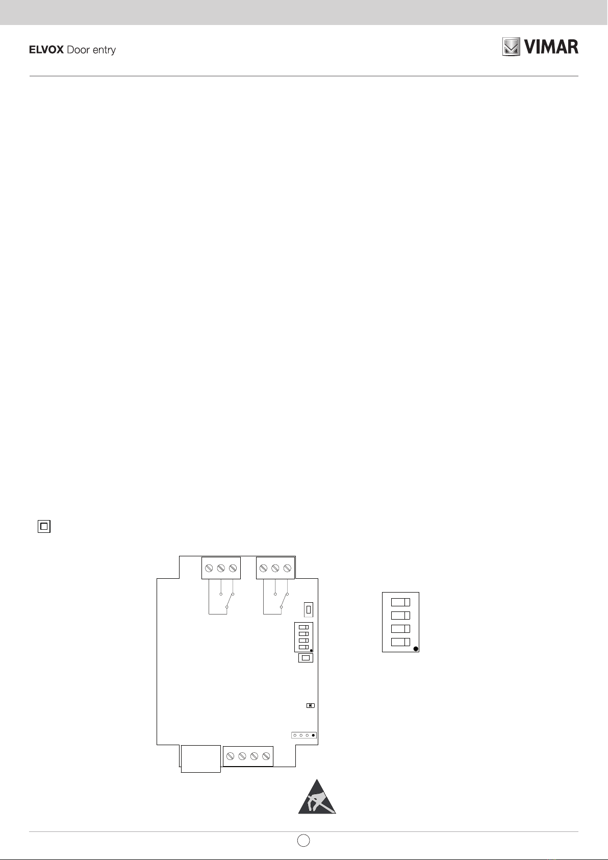
Monostable relay • 69PH identifier (see paragraph 4 “ID assignment”)
• Operating modes = “DEFAULT”
• Group 1 = 0
• Group 2 = 0
• Group 3 = 0
• Group 4 = 0
• T1 delay time (def. 1s)
• T2 activation time (def. 1s)
Call-activated monostable relay • Operating modes = “Monost.Call Accept.”
• Enabling map = enable devices that send and receive the call (all enabled by default)
• T1 delay time (def. 1s)
• T2 activation time (def. 1s)
Door lock command activated monos-
table relay
• Operating modes = “Monost. On SR”
• Enabling map = enable devices that send and receive the command (all enabled by default)
• T1 delay time (def. 1s)
• T2 activation time (def. 1s)
Monostable relay activated by com-
mand F1
• Operating modes = “Monost. On F1”
• Enabling map = enable devices that send and receive the command (all enabled by default)
• T1 delay time (def. 1s)
• T2 activation time (def. 1s)
Monostable relay activated by com-
mand F2
• Operating modes = “Monost. On F2”
• Enabling map = enable devices that send and receive the command (all enabled by default)
• T1 delay time (def. 1s)
• T2 activation time (def. 1s)
Call attempt activated monostable relay • Operating modes = “Call Att.Enabl.Map”
• Enabling map = enable devices that send and receive the call (all enabled by default)
• T1 delay time (def. 1s)
• T2 activation time (def. 1s)
Monostable relay activated by call at-
tempt to master unit
• Operating modes = “Call Att.to Group”
• Group 1 = ID indoor station
• Group 2 = ID indoor station
• Group 3 = ID indoor station
• Group 4 = ID indoor station
• T1 delay time (def. 1s)
• T2 activation time (def. 1s)
Button-activated bistable relay • 69PH identifier (see paragraph 4 “ID assignment”)
• Operating modes = “Bistable”
• T1 activation delay time (def. 1s)
• T2 deactivation delay time (def. 1s)
• FLAG “State Not.” (YES = sends status with each switch, NO = does not send)
Bistable relay activated by accepted call. • Operating modes = “Bist.Accept.Call”
• Enabling map = enable devices that send and receive the command (all enabled by default)
• T1 activation delay time (def. 1s)
• T2 deactivation delay time (def. 1s)
• FLAG “Int.Call” (YES = Deactivates at end of call. NO = Deactivates on answering or, if external call, at end of electronic unit chime cycles)
Call repeater • Operating modes = “Default”
• Group 1 RL1 = Group 1 RL2 = ID indoor station
• Group 2 RL1 = Group 2 RL2 = ID indoor station
• Group 3 RL1 = Group 3 RL2 = ID indoor station
• Group 4 RL1 = Group 4 RL2 = ID indoor station
• “Chime cycles” = desired number of cycles
Generic call repeater • Operating modes = “Default”
• Group 1 RL1; Kind of call repeated for Group 1 RL1
• Group 2 RL1; Kind of call repeated for Group 2 RL1
• Group 3 RL1; Kind of call repeated for Group 3 RL1
• Group 4 RL1; Kind of call repeated for Group 4 RL1
• Group 1 RL2; Kind of call repeated for Group 1 RL2
• Group 2 RL2; Kind of call repeated for Group 2 RL2
• Group 3 RL2; Kind of call repeated for Group 3 RL2
• Group 4 RL2; Kind of call repeated for Group 4 RL2
• “Chime cycles” = desired number of cycles
N.B. For repetition of calls from 6120, the “landing group” flag of the called indoor station must be enabled.
Call repeater from 6120 • Operating modes = “Call Rep. 6120"
• Enabling map = enable devices that send and receive the call (all enabled by default)
• “Chime cycles” = desired number of cycles
Roller Shutter mode • Operating modes = “Roller Shutter Mode”
• T1 delay time (def. 1s)
• T2 activation time (def. 1s)
Call progression • Operating modes = “Call progression”
Table 6
7
EN
69PH

TABELLA PROGRAMMAZIONI EFFETTUABILI CON PROGR. ART. 950C O CON SOFTWARE “SAVEPROG”
TABLE OF PROGRAMMING PROCEDURES POSSIBLE WITH PROG. ART. 950C OR “SAVEPROG” SOFTWARE
Table 7
Type of parameter Parameter selection Values
Description 950C Save Prog 950C Save Prog Min Max
Group “Group” “GROUP” “DEV. GROUP GROUP 1, 2, 3, 4 0200
[40000]
Kind of call
repeater
"Call Rep. Type” “Call repeater type” "Call Rep. for Grp. 1"
"Call Rep. for Grp. 2"
"Call Rep. for Grp. 3"
"Call Rep. for Grp. 4"
“EXT.” “INT” “6120” (select with check box) 08 [50]
(enabling with flag for SaveProg)
Operating modes "Op. Modes" "Relay Type" “Default”
“En.Map Call Rep.”
"Bistable"
"Att.Call to Group"
“Att.Call En.Map”
"Monost.Acc.Call"
“Bist.Acc. Call”
“Monostab. On F1”
“Monostab. On F2”
“Monostab. On SR”
“Call Rep. 6120"
"Roller Shutter Mode"
“Call Progress.”
DEFAULT
CALL REPEATER ON ENABLING MAP
BISTABLE
ATTEMPTED CALL TO GROUP
ATTEMPTED CALL ON ENABLING MAP
MONOSTABLE ON ACCEPTED CALL
BISTABLE ON ACCEPTED CALL
MONOSTABLE ON F1
MONOSTABLE ON F2
MONOSTABLE ON LOCK
CALL REPEATER FROM 6120
ROLLER SHUTTER MODE
CALL PROGRESSION
Select the desired type and press OK
Delay and
activation time
"Activ. Time" “Delay and
activation time”
“T.DelayOn(s)”
“T.On (s)”
DELAY
ACTIVATION
0 (s) 32767 (s)
0h 0m 0s 9h 6m 7s
Chime cycles “Chime cycles” “Number of Cycles” 020
Enabling map “Enabl. map” “Enabling Map” “Internal”
“Entrance panels”
"Auxiliary units"
“Switchboards”
“Devices”
“Entrance panels”
“6120”
“Switchboards”
Select the Group and confirm with
OK, enter the first value and confirm,
enter the second value and confirm
with OK.
Min 0 / Max 65535 (window)
Flag “Flag” “Flag” “Int.Call”
"Not.Status"
“xxxxxx”
“Call End Only”
"Notify Status"
“xxxxxxx”
enable (NO / YES)
(check box)
xxxxxx
8EN
69PH

PROGRAMMING RELAYS OVER HORIZONTAL BUS
CAUTION: TO ACTIVATE THE RELAYS CONNECTED TO THE HORIZONTAL BUS, IT IS NECESSARY TO REMAP THE ROUTER 69RS ASSIGNING AN "EXTENDED" IDENTIFICATION ID
(SEE ROUTER INSTRUCTIONS art. 69RS).
THE EXTENDED ID CAN ONLY BE ASSIGNED VIA THE PROGRAMMER 950C OR SAVEPROG
MANUAL PROGRAMMING
1) Reset default data
PROGRAMMING WITH PROGRAMMER ART. 950C OR "SAVEPROG" SOFTWARE - HORIZONTAL BUS
2) ID assignment
3) Monostable relay with activation by buttons on the indoor stations
4) Call-activated monostable relay
5) Monostable relay activated by F1, F2 or lock buttons on the indoor station
6) Monostable relay activated by call attempt
7) Monostable relay activated by attempt to call group
8) Bistable relay with activation by indoor station buttons
9) Call-activated bistable relay
10) Call repeater (only remapping the relay and assigning the relay with the same ID as the indoor station where the call must be repeated).
11) Roller shutter mode
12) Enabling map
HORIZONTAL BUS MANUAL PROGRAMMING
1) RESET DEFAULT DATA
The reset procedure allows factory settings to be restored (default configuration).
- Press and hold down buttons RST and P1 simultaneously.
- Release RST but continue to hold down P1 until the LED begins to flash.
- While the LED flashes release P1 and press P1 immediately.
- Hold down P1 until the LED goes out.
- Release P1.
NOTE: In the default configuration, the operating mode is of a monostable relay.
PROGRAMMING WITH PROGRAMMER ART. 950C OR WITH “SAVEPROG” PC SOFTWARE
2) ID ASSIGNMENT
For the Horizontal Bus the ID of the Relay Modules art. 69PH must be entered via the programmer 950C or SaveProg software (the procedures for managing the ID are described on page 11 and 12).
3) MONOSTABLE RELAY WITH ACTIVATION BY BUTTONS ON INDOOR STATION
The relays activate with a delay time T1 and remain active for a time T2 before returning to rest.
Relay RL1 is activated by pressing button P2 and relay RL2 by pressing button P3 on the indoor station. All the indoor stations can activate RL1 and RL2, subject to the buttons provided on the
indoor station and their configuration. In this mode relays RL1 and RL2 can also operate individually.
4) CALL-ACTIVATED MONOSTABLE RELAY
The relay is activated when a call is sent to an indoor station present in the system, which accepts the call. It activates with a delay time T1 after the call is sent and remains active for a time T2.
After that, the relay returns to its initial position. The devices that send the call and the devices that receive the call can be configured via the “enabling map”. By default all devices are enabled.
5) MONOSTABLE RELAY ACTIVATED BY F1, F2 OR LOCK BUTTONS ON THE INDOOR STATION
The relay activates when the door lock opening or F1 or F2 commands are given by pressing the corresponding button on the indoor station. The relay activates with a delay time T1 after receiving
the command and remains active for a time T2. The devices that send and receive the command can be configured according to the “Enabling map”. By default all devices are enabled.
6) MONOSTABLE RELAY ACTIVATED BY CALL ATTEMPT
The relay activates when a call is sent to a device that may not be present in the system or may decline the call. The relay activates with a delay time T1 after the call is sent and remains active for
a time T2. The devices that send the call and those that receive the call can be configured via the “Enabling map”. By default all devices are enabled.
7) MONOSTABLE RELAY ACTIVATED BY ATTEMPT TO CALL GROUP
The relay activates when a call is sent to an indoor station that may not be present in the system or may decline the call. The relay activates with a delay time T1 after the call is sent and remains
active for a time T2. The ID of the indoor station that receives the call must be programmed in the “GROUP” parameter. It is possible to have up to four different indoor stations.
8) BISTABLE RELAY WITH ACTIVATION BY INDOOR STATION BUTTONS
The relay switches its state every time it receives a command sent to it.
Example: Relay RL1 is not active, button P2 has been programmed to activate AUXILIARY 1. On pressing P2, RL1 activates with a delay time T1. On pressing P2 again, the relay deactivates with
a delay time T2. In this operating mode the relay can send a switching confirmation message to the device that has activated it, activating the “Not.Status” flag.
9
EN
69PH

9) BISTABLE RELAY ACTIVATED BY ACCEPTED CALL
The relay activates when a call is sent to a device present in the system, which then accepts the call.
The relay can be deactivated differently according to the status of the “Int.Call” flag:
- If the “Int. Call" Flag = NO: the relay deactivates on completion of the chime cycles set on the electronic unit (if an external call), when the call is answered or at the end of the call.
- If the “Int. Call" Flag = YES: the relay deactivates only at the end of the call.
The devices that send the call and those that receive the call can be configured via the “Enabling map”. By default all devices are enabled.
NOTE: The ID identification numbers reserved for the relays connected to the HORIZONTAL BUS are from number 2951 to 3000. It is still possible to assign different ID identification numbers
(from 1 to 40000). In this case, however, unwanted activations may occur. If a relay on the HORIZONTAL BUS is assigned for example ID 1 and on the VERTICAL BUSES ID 1 has been assigned,
when activating an activation command for the relay with ID 1 on the vertical BUS, the relay on the HORIZONTAL BUS may also activate. This activation could instead be desired in cases when
there is a need for simultaneous activation.
10) CALL REPEATER
In this mode, you can repeat the call of an electronic unit connected over the Horizontal Bus, remapping the relay with an indoor station ID.
11) ROLLER SHUTTER MODE
This operating mode is used to control roller blinds, shutters, awnings, etc. In this mode the two relays RL1 and RL2 are interlocked to avoid simultaneous activation of the two relays. When relay
RL1 activation button is pressed, it switches with a delay time T1, then maintains this position for a time T2 or until the same activation button is pressed again. When in an activated state, the
relay is also deactivated by pressing the control button of the other relay. If the two relays control the two directions of rotation of a motor (e.g. the reduction gear of a roller shutter), it is advisable
to maintain a minimum relay activation delay time (default = 1s) so that the motor passes through a stationary state when reversing its direction of rotation.
12) ENABLING MAP
In "Horizontal Bus" mode it is possible to enable or disable indoor stations, electronic units, auxiliary units and switchboards, subject to an operating window where the start and end ID numbers
are to be entered. From the INTERNAL, ENTRANCE PANEL, AUXILIARY, SWITCHBOARD submenus, there are 3 windows (WIN #1, WIN #2, WIN # 3) where for each one you can enter the
initial and final ID so as to configure the "operating window". Confirm with OK.
NOTE: The end number must not be any less than the start number.
To have all the numbers enabled, simply enter number 1 in the first enable and the maximum number in the second enable of WIN# 1.
13) REMAPPING RELAYS FOR OPERATION OVER HORIZONTAL BUS
The ID identification codes that can be assigned to a relay in operating mode over "extended" Elvox DueFili Bus range from ID 2951 to ID 3000.
It is in any case possible to assign a relay with IDs from 1 to 3000. In this case, however, if there are relays with ID 1 to 8 in the VERTICAL BUSES there may be simultaneous activation of the
relays with the same ID.
Relay activation takes place via the buttons on the indoor stations (see product instructions).
14) REMAPPING FOR CALL REPEATER CONFIGURATION
If, on the contrary, it is necessary to repeat the call from an electronic unit connected on the Horizontal Bus, you need to assign the ID of the indoor station to which the call must be repeated.
Example: when an electronic unit sends code ID = 601 (corresponding to indoor station 1 referred to router ID = 4), you want relay 69PH to activate a function. In this case we will use the call
repeater function and the identifier to be assigned to the relay will be ID = 601.
15) Call progression
Set it for relay 1. Configuration of relay 2 should be kept by default because its operation depends closely on relay 1.
Call Progression mode envisages the following behaviour of relays 1 and 2.
Relay 1 of 69PH is closed the moment a call from an associated outdoor station is recognised (and directed at any indoor station, switchboard, etc.).
Relay 1 of 69PH is opened the moment an associated outdoor station exits the call in progress state (in other words it enters the in call or standby state).
Relay 2 of 69PH is closed the moment an associated outdoor station exits the call in progress state.
Relay 2 of 69PH is opened the moment an associated outdoor station exits the call in progress, or the standby state.
Self-start is managed as the call in progress state (without transition via call state) and the behaviour of the 69PH relays will be consistent with this.
10 EN
69PH

gura - gure 4
Programming with 950C
Connect the 950C programmer to the programming connector (see Fig.1) and wait for a few seconds until the following message appears on the display: “Select Function: Program Config”.
- Press the button. The message on the display becomes: ”Select Function: Terminal Mode”
- Press the button, a text appears indicating the set message language (Italian by default). To select the language, press for Italian or for English.
Press the button. The following message appears: “Installation”.
With you enter the Installation menu and you can view the configuration. To keep the current position press . To change the configuration, press the button. In this way it varies
from one bus type to another. If the configuration is changed (e.g. from Vert you to change to Horiz) via , and confirm with . If the ID number is the one you want, press , otherwise
enter the number and confirm with , the DONE confirmation message will be displayed.
NOTE: If 0 is entered, the "New ID DipSw" message will be displayed, confirm with ,
the DONE confirmation message will be displayed.
Confirm with , you are prompted for the ID number to assign to 69PH. You can confirm the identification number displayed with or modify it by entering the number on the programmer
keypad and confirm with . Press to return to the position in the INSTALLATION menu to continue with the configuration.
From INSTALLATION press Relay 1 or 2 will appear.
By pressing , only if the relay 69PH is in the Vertical Bus configuration, you can the procedure for entering data referred to the IDs for the appliances to be enabled if internal, panels (elec-
tronic units), auxiliary units or switchboards. On ENABLING MAP TYPE with button you can choose between SINGLE or WINDOW ID. Depending on this configuration, on ENABLING
MAP (see programming diagram) you can enter the identifiers by identification number or a window of operation indicating the starting ID and the end ID. For example, by entering 10 and 30, the
enabled identifiers will be IDs from 10 to 30.
To continue with the configuration, press the button to return to RELAY 1 or 2.
Enter 1 or 2 to choose whether to configure relay 1 or 2 and confirm with , you can continue with the configuration of the GROUP, REPEATER CALL TYPE, OPERATING MODES, etc. To
configure one of the menu items (e.g. operating modes), press and scroll through the submenu with the button. To confirm the function, confirm with . Upon confirmation DONE
is displayed. To exit the submenu, press the button.
950C programmer keypad:
- Button: to confirm (upon confirmation the message displayed reads “Done!”)
- Button: returns up a level or cancels typing
- Button: to quit programming
- Arrows button : to navigate from one menu to another and through the submenus.
- Numbers button , : used to indicate the number
of the Group and the ID, to select the language and to activate the flags.
NOTE: ON/OFF is not active.
11
EN
69PH

gura - gure 6
Programming with SAVEPROG software
SaveProg is a PC software package supplied together with interfaces
Art. 692I and 692I/U. Install the software on the PC. Launch the pro-
gram by clicking on the icon.
The image of Figure 5 is displayed.
NOTE: When the relay is connected to the HORIZONTAL BUS
check o the Flag. HORIZONTAL BUS as indicated by the arrow.
Select the icon highlighted by the arrow in Figure 6, the window
appears where you can select the Relay 69PH EXTENDED). After
confirming with OK the configuration window will open for the 69PH.
Remove the check mark from Mode
692R.
gura - gure 5
gura - gure 7
gura - gure 8
12 EN
69PH

ID 69PH
With installation over vertical Bus it is possible to assign an ID code number from 1 to 8.
By entering the number 0, manual assignment using the dip-switches will take priority.
With installation over horizontal Bus it is possible to assign an ID code number from 1 to 40000. In this configuration there is no assigning the number 0. Default: 0.
Indoor station enabling map
It is possible to limit the number of indoor stations that can send commands to the relay art. 69PH. Check off the list of enabled indoor stations. Default: all selected
Chime cycles
Configuring the number of activation cycles when art. 69PH is used as a chime repeater. Range: 0..20, Default: 5.
Delay Time art. 69PH
This enables configuring a delay time from sending the activation command to the moment when the relay is activated.
Range: from 0 to 8 hours, 59 minutes, 59 seconds. Default: 1 second
(De)Activation Time
This is the activation time in the case of monostable operation and the deactivation time in the case of a bistable relay, from 0 to 8 hours, 59 minutes, 59 seconds. Default: 1 second
Groups
Both relays in the single art. 69PH can have their own distinct set of four masters. These are indoor station IDs, and for each ID you can decide whether the corresponding relay must be acti-
vated on a call from an electronic unit, intercom, button art. 6120 or a combination of the three.
The masters can be indoor stations or switchboards. Default: all empty
Relay Map and 6120
It is possible to limit the operation of each relay art. 69PH for one or more relays or button modules art. 6120 (using the same relay address space). Check off the list of relays / art. 6120 to your
interest. Default: all selected
REFERENCE VERTICAL BUS CONFIGURATIONS FIGURE 8
ID = for assigning the ID of the relay module.
HORIZONTAL BUS = do not check o
LANGUAGE = to choose the language of the texts
ENABLE SINGLE DEVICE (checked) = for conguration by checking o the check box
to dene which devices are enabled or not. If the ag is not checked o, a starting and an
ending ID need to be entered with the ID identier number of the enabled devices (there
are 3 windows).
DEVICES and 6120 = connected with the conguration by checking o the ENABLE ag.
SINGLE DEVICE = If checked o, all the devices are enabled. If not checked o, the
devices to be enabled must be indicated from the lowest number to the highest number in
order to generate a window of operation. Three windows are available.
RELAY CHOICE = to choose which relay 1 or 2 to congure.
RELAY TYPE = to be selected via the drop-down menu, the type of operation to be activat-
ed (see also PROGRAMMING DIAGRAM).
NUMBER OF CYCLES = Number of actuator activation repetitions.
DELAY = delay time after receiving the command
ACTIVATION = time of implementation of the command
GROUP/DEV.= assigning a device to a master
REFERENCE HORIZONTAL BUS CONFIGURATIONS FIGURE 8
ID = for assigning the ID of the relay module.
HORIZONTAL BUS = check o (the check box disappears ENABLE SINGLE DEVICE)
LANGUAGE = to choose the language of the texts
DEVICES and 6120 = the devices to be enabled must be indicated from the lowest number
to the highest number in order to generate a window of operation. Three windows are
available.
RELAY CHOICE = to choose which relay 1 or 2 to congure.
RELAY TYPE = to be selected via the drop-down menu, the type of operation to be activat-
ed (see also PROGRAMMING DIAGRAM).
NUMBER OF CYCLES = Number of actuator activation repetitions.
DELAY = delay time after receiving the command
ACTIVATION = time of implementation of the command
GROUP/DEV.= assigning a device to a master
ID
When the conguration is done manually, that is with the dip-switches, manual conguration prevails over any software conguration (with the programmer). Software assignment is therefore
irrelevant.
When the DIP switch is set to "0", you can assign the ID via the software conguration (with the programmer).
13
EN
69PH

GROUP
DEV. GROUP 4
DEV. GROUP 3
DEV. GROUP 1
DEV. GROUP 2
Op. Modes
Call Rep.Type
Call Rep. for Grp. 1 Default
Monostab. On SR
Monostab. On F2
Monostab. On F1
Bist.Acc. Call
Monost.Acc.Call
Att.Call En.Map
Att.Call to Group
Bistable
Call Rep. 6120
Roller Shutter Mode
Call Rep. for Grp. 2
Call Rep. for Grp. 3
Call Rep. for Grp. 4
TERMINAL MODE
VERT ID = 1
HORIZ ID = 1
ITALIAN =
ENGLISH =
Programming Diagram
Table for programming parameter "Call Rep. Type”:
Set Function
0 (Default) Repeats external calls for devices programmed in GROUP parameter
1 Repeats EXTERNAL calls for GROUP
2 Repeats INTERCOM calls
3 Repeats EXTERNAL and INTERCOM calls
4 Repeats calls from 6120
5 Repeats EXTERNAL calls and calls from 6120
6 Repeats INTERCOM calls and calls from 6120
7 Repeats EXTERNAL and INTERCOM calls and calls from 6120
To change operating mode:
• Select the desired operating mode
• Press OK to confirm
En.Map Call Rep.
INSTALLATION RELAY 1 or 2
Window present
only in
“Vertical”
configuration
En.Map Type
- with windows
- single ID
The parameter is changed by
pressing button 1
Enter or to select the relay to be
configured and confirm with
2.
and enter
the first menu
With you change the configuration
(Vert / Horiz), you confirm with
2.
and
enter the ID number to assign to 69PH
In the GROUP submenu, enter the num-
ber to assign and conrm with
2.
.
Press to go back to the menu
GROUP
Press for menu
ENABLING MAP TYPE
Press for menu
RELAY 1 or 2
2.
2.
2.
2.
5
2.
5
5
Call Progression
14 EN
69PH

Flag
Enabl. map
Chime cycles
Activ. Time
T.On (s)
T.DelayOn (s)
Switchboards
Auxiliaries
Entrance panels
Internal
Not.Status
0=NO 1=YES
Int.Call
0=NO 1=YES
(0 - 20)
Default 5
Internal xxx
YES
Dis/enable a device by single ID
• select “Enabl. Map” and press OK,
• select the device category: “internal”, “entrance panel”, “auxiliary”,
“switchboard”,
• scroll through the list of devices: the ID of the selected device ap-
pears at the top right, on the line below the status (YES = enabled,
NO = disabled)
• a device can be accessed directly by keying in its ID (e.g. for indoor
station with ID = 50, key in 50 and press OK)
• press the button 0 to change the status of the device (e.g. YES -> 0
-> NO -> 0 YES) and then OK to save the new status.
Dis/enable category by window
• select "Enabl. Map" and press OK,
• select the device category: "internal",
"panel", "auxiliary", "switchboard" and confirm with OK to access the
category to configure.
• In window 1 WIN # 1, indicate the ID of the first device, confirm with
OK, specify the ID of the last device of the window of devices to be
enabled and confirm with OK (entering 3, 20 enables devices from 3
to 20). There are 3 windows available (WIN#1, WIN#2, WIN#3) so it is
possible to obtain up to 3 enabling Groups.
This operation is available for both vertical and horizontal mode.
INTERNAL WIN# 1
[ 1] 40000
• To move from one menu to another press the or buttons
• To enter from the menu to a submenu, press the button (e.g. from
GROUP to DEV. GROUP 1).
• To move from one submenu to another press the or buttons
• To exit a submenu and return to the menu, press the button
•
To modify a parameter:
• Select the parameter.
• Type in the new value.
• Press to confirm, to cancel press and you go back to the previous
value.
• * On the left there are the buttons to return to the previous level, on the
right the buttons to proceed with the next conguration.
2.
2.
2.
2.
15
EN
69PH

B1
12B2
PRI
K
4
T2 5
6S
T1 2
1
A
T4 -
+
C
B
VIDEO
T3 6P
12
1
E+
FP
E-
2
M
CH
+12
M
V3
A
C
B
4
12
2
3
1
13
K
K
B
A
C
*
*
*
C
A
B
+12
CH
M
2
E-
FP
E+
1
K
*
+I+U-
PRI
OUT
IN
PRI 4758
IN
OUT
8574PRI
CBA
NC
B2B1
1C
12
NO
ID=1
NC2C NO
CBA
NC
B2B1
1C
12
NO NC2C NO
CBA
NC
B2B1
1C
12
NO NC2C NO
OUT
IN
PRI 4758
IN
OUT
8574PRI
CBA
NC
B2B1
1C
12
NO NC2C NO
CBA
NC
B2B1
1C
12
NO NC2C NO
P
L
D0
EXT+
EXT-
M
PA
X
VLED
B1
B2
S+
S-
F2
F1
SR
-L
+12V
M
M
CA
D
EXT+
EXT-
M
PA
X
VLED
B1
B2
S+
S-
F2
F1
SR
-L
+12V
M
M
CA
P
L
1C
NO
NC
2C
NO
NC
3
2
1
6
9
45
78
R0C
X
R
OUT
IN
CBA
NC
B2B1
1C
12
NO
ID=1
NC2C NO
1C
NO
NC
2C
NO
NC
B1
12B2
PRI
K
4
T2 5
6S
T1 2
1
A
T4 -
+
C
B
VIDEO
T3 6P
12
1
E+
FP
E-
2
M
CH
+12
M
V3
A
C
B
4
12
2
3
1
13
K
K
B
A
C
*
*
*
C
A
B
+12
CH
M
2
E-
FP
E+
1
K
*
+I+U-
PRI
OUT
IN
PRI 4758
IN
OUT
8574PRI
CBA
NC
B2B1
1C
12
NO
ID=1
NC2C NO
CBA
NC
B2B1
1C
12
NO NC2C NO
CBA
NC
B2B1
1C
12
NO NC2C NO
OUT
IN
PRI 4758
IN
OUT
8574PRI
CBA
NC
B2B1
1C
12
NO NC2C NO
CBA
NC
B2B1
1C
12
NO NC2C NO
P
L
D0
EXT+
EXT-
M
PA
X
VLED
B1
B2
S+
S-
F2
F1
SR
-L
+12V
M
M
CA
D
EXT+
EXT-
M
PA
X
VLED
B1
B2
S+
S-
F2
F1
SR
-L
+12V
M
M
CA
P
L
1C
NO
NC
2C
NO
NC
3
2
1
6
9
45
78
R0C
X
R
OUT
IN
CBA
NC
B2B1
1C
12
NO
ID=1
NC2C NO
1C
NO
NC
2C
NO
NC
Variante per ripetizione della chiamata esterna con una
suoneria supplementare Art. 860A in modalità ripetitore
di chiamata.
Variante per ripetizione della chiamata intercomunicante
con suoneria supplementare Art. 860A in modalità ripe-
titore di chiamata.
Variante per ripetizione della chiamata esterna e chia-
mata intercomunicante con due toni diversi di una suo-
neria supplementare Art. 860A in modalità ripetitore di
chiamata.
X
X
X
X
X
U-
Art. 69PH
U-
Art. 69PH
U-
Art. 69PH
Z2 Z2
Z2
U - Relè Art. 69PH
X - Cavo Art. 732H, 732I (Due Fili Twistati)
Z2 - Suoneria supplementare Art. 860A
***
Rete-Mains Rete-Mains Rete-Mains
Montante Montante Montante
MontanteMontanteMontante
B1
12B2
PRI
K
4
T2 5
6S
T1 2
1
A
T4 -
+
C
B
VIDEO
T3 6P
12
1
E+
FP
E-
2
M
CH
+12
M
V3
A
C
B
4
12
2
3
1
13
K
K
B
A
C
*
*
*
C
A
B
+12
CH
M
2
E-
FP
E+
1
K
*
+I+U-
PRI
OUT
IN
PRI 4758
IN
OUT
8574PRI
CBA
NC
B2B1
1C
12
NO
ID=1
NC2C NO
CBA
NC
B2B1
1C
12
NO NC2C NO
CBA
NC
B2B1
1C
12
NO NC2C NO
OUT
IN
PRI 4758
IN
OUT
8574PRI
CBA
NC
B2B1
1C
12
NO NC2C NO
CBA
NC
B2B1
1C
12
NO NC2C NO
P
L
D0
EXT+
EXT-
M
PA
X
VLED
B1
B2
S+
S-
F2
F1
SR
-L
+12V
M
M
CA
D
EXT+
EXT-
M
PA
X
VLED
B1
B2
S+
S-
F2
F1
SR
-L
+12V
M
M
CA
P
L
1C
NO
NC
2C
NO
NC
3
2
1
6
9
45
78
R0C
X
R
OUT
IN
CBA
NC
B2B1
1C
12
NO
ID=1
NC2C NO
1C
NO
NC
2C
NO
NC
Schema di collegamento con modulo programmabile 69PH per due servizi ausiliari / Wiring diagram with programmable module 69PH for two auxiliary
services (SI646)
2° Relè
Contatto C/NO/NC
Carico massimo 6A 230V
1° Relè
Contatto C/NO/NC
Carico massimo 6A 230V
Montante videocitofonico
X
X
U-
Art. 69PH
Montante
U - Relè Art. 69PH
X - Cavo Art. 732H, 732I (Due Fili Twistati)
*
Y1
Y1 Y2
Y2
Variant for external call repetition with additional chime
Art. 860A in call repeater mode.
Variant for intercom call repetition with additional chime
Art. 860A in call repeater mode.
Variant for external call and intercom call repetition with
two different tones of additional chime Art. 860A in call
repeater mode.
U - Relay Art. 69PH
X - Cable type 732H, 732I (Twisted Pair)
Z2 - Additional chime Art. 860A
Cable riser Cable riser Cable riser
Cable riserCable riserCable riser
2nd Relay
C/NO/NC Contact
Maximum load 6A 230V
1st Relay
C/NO/NC Contact
Maximum load 6A 230V
Video door entry cable riser
Cable riser
U - Relay Art. 69PH
X - Cable type 732H, 732I (Twisted Pair)
16 EN
69PH

The instruction manual can be downloaded from www.vimar.com
Installation rules
• Installation and conguration must be carried out by qualied persons in compliance with the current regulations regarding the installation of electrical equipment in the country where the products
are installed.
• Install the device at a height of no more than 2 m.
IMPORTANT: The power supply must be connected to the a.c. mains by way of an easily accessible double pole switch having a gap of at least 3 mm between contacts.
• The relay output power supply circuits must be protected against overloads by installing devices or fuses with a rated breaking capacity of 1500 A or automatic 1-way switches type C, with a
rated current not exceeding 10 A.
Regulatory compliance
• LV Directive. EMC Directive. RoHS directive.
• Standards: Standards EN 62368-1, EN 55032, EN55035.
• REACH (EU) Regulation no. 1907/2006 – Art.33. The product may contain traces of lead.
• The power supply units constitute a SELV source in observance of the requirements set out in Article 411.1.2.2 of CEI standard 64-8 (ed. 2012).
WEEE - Information for users
If the crossed-out bin symbol appears on the equipment or packaging, this means the product must not be included with other general waste at the end of its working life. The user must
take the worn product to a sorted waste center, or return it to the retailer when purchasing a new one. Products for disposal can be consigned free of charge (without any new purchase
obligation) to retailers with a sales area of at least 400m2, if they measure less than 25cm. An ecient sorted waste collection for the environmentally friendly disposal of the used device,
or its subsequent recycling, helps avoid the potential negative eects on the environment and people’s health, and encourages the re-use and/or recycling of the construction materials.
17
EN
69PH

Viale Vicenza 14
36063 Marostica VI - Italy
www.vimar.com
49400649C0_MI_IT 00 2111
Other manuals for ELVOX 69PH
1