DFI reserves the right to change the specifications at any time prior to the
product's release. This QR may be based on editions that do not resemble your
actual products. For more documentation and drivers, please visit the download
page at https://go.dfi.com/WL051, or via the QR code to the right.
15 Front Panel Pin Assignment Pin Assignment
1 PWSIN 2 3V3SB
3 GND 4 SUS_LED
5 RESET 6 HD_LED
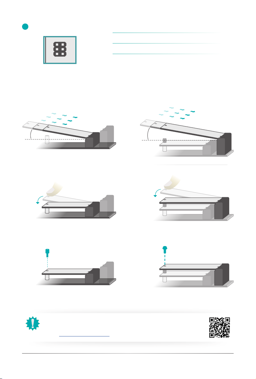
Step 1: Step 4:
Step 2: Step 5:
Step 3: Step 6:
M.2 Stack Installation
4Quick Reference | WL051
1
2
G12 G7 G3
G1
G2
1
10
2
9
1
1
9
2
10
10
2
9
1
6
21
40
G3
G2
1
8
5
1
4
G2 G1
M2 M1
1
75
2
74
33
32
23
22
G2 G1
M2 M1
1
75
274
21
20
11
10
G3
G2G1
M2
M1
1 75
2 74
21
20
11
10
G3
1
2
C
A
A
C
C
A
C
1
2
B E
C
B
E
C
1
5
1
5
1
5
1
5
64
3
1
1
3
4
6
3
4
6
1
4
6 1
34
6
1
61
1
6
1
6
3
3
4
1
4
1
3
4
61
4
6
1
4
1
1
4
3
4
1
1
7
1
7
1
14
8
1
7
9
16
1
8
2
G1
G2
M1
M2
L1 L3
L2 L4
P1 P10
P10
P1
L4
L2 L3
L1
M2 M1
G2 G1
85
1
7
12
1
65
8
16
31
24
8
1
9
15
16
31
24
1
9
9
1
8
31
15
S1
S2
S3
S4
1
4
59
13
14
10
18
19
2
1
20
21
G4
G1 G2
G3
1
13
24
36
37
48
3
1
6
13
45
1
3
1
3
5
5
4
3
11
2
3
G S
D
31
40
21
1
7
5
11
1
5
1
AC
4
1
14
C
A
14
C
A
1 4
C
A
64
48
32
17
1
1
3
Front Panel
DIO
USB2_6/7
COM1
M2CN3.G3
M2CN2.G3
A
SPI
eDP
LAN1
LAN2
M.2-E
M.2-B
C
C
B
B
A
CN3
TSJ1
UBJ1
J4
J7
CN14
M2CN1
M2CN3
M2CN2
CN1
J1
ETCN2
ETCN1
UBCN1
CN2
JP1
CN13
UBCN8
1
1 2
10
1
1
2
10 9
1
2
6
1
M.2 Module M.2 Socket
Key
Stand-off
Notch
M.2 Module M.2 Socket
Key
Stand-off
Notch
M.2 Module M.2 Socket
Key
Stand-off
Notch
M.2 Module M.2 Socket
Key
Stand-off
Notch
M.2 Module M.2 Socket
Key
Stand-off
Notch
M.2 Module M.2 Socket
Key
Stand-off
Notch