VIPA 900-2C610 User manual

VIPA Accessories
Teleservice module | 900-2C610 | Manual
HB39E_TM | RE_900-2C610 | Rev. 13/28
July 2013

Copyright © VIPA GmbH. All Rights Reserved.
This document contains proprietary information of VIPA and is not to be disclosed or used except in accordance with applicable
agreements.
This material is protected by the copyright laws. It may not be reproduced, distributed, or altered in any fashion by any entity (either
internal or external to VIPA), except in accordance with applicable agreements, contracts or licensing, without the express written
consent of VIPA and the business management owner of the material.
For permission to reproduce or distribute, please contact:
VIPA, Gesellschaft für Visualisierung und Prozessautomatisierung mbH
Ohmstraße 4, D-91074 Herzogenaurach, Germany
Tel.: +49 (91 32) 744 -0
Fax.: +49 9132 744 1864
http://www.vipa.com
Note
Every effort has been made to ensure that the information contained in this document was complete and accurate at the time of
publishing. Nevertheless, the authors retain the right to modify the information. This customer document describes all the hardware
units and functions known at the present time. Descriptions may be included for units which are not present at the customer site. The
exact scope of delivery is described in the respective purchase contract.
CE Conformity Declaration
Hereby, VIPA GmbH declares that the products and systems are in compliance with the essential requirements and other relevant
provisions.
Conformity is indicated by the CE marking affixed to the product.
Conformity Information
For more information regarding CE marking and Declaration of Conformity (DoC), please contact your local VIPA customer service
organization.
Trademarks
VIPA, SLIO, System 100V, System 200V, System 300V, System 300S, System 400V, System 500S and Commander Compact are
registered trademarks of VIPA Gesellschaft für Visualisierung und Prozessautomatisierung mbH.
SPEED7 is a registered trademark of profichip GmbH.
SIMATIC, STEP, SINEC, TIA Portal, S7-300 and S7-400 are registered trademarks of Siemens AG.
Microsoft und Windows are registered trademarks of Microsoft Inc., USA.
Portable Document Format (PDF) and Postscript are registered trademarks of Adobe Systems, Inc.
All other trademarks, logos and service or product marks specified herein are owned by their respective companies.
Information product support
Contact your local VIPA Customer Service Organization representative if you wish to report errors or questions regarding the contents
of this document. If you are unable to locate a customer service center, contact VIPA as follows:
VIPA GmbH, Ohmstraße 4, 91074 Herzogenaurach, Germany
Telefax:+49 9132 744 1204
Technical support
Contact your local VIPA Customer Service Organization representative if you encounter problems with the product or have questions
regarding the product. If you are unable to locate a customer service center, contact VIPA as follows:
VIPA GmbH, Ohmstraße 4, 91074 Herzogenaurach, Germany
Telephone: +49 9132 744 1150 (Hotline)

Manual VIPA TM Contents
HB39E - TM - RE_900-2C610 - Rev. 13/28 i
Contents
About this manual .................................................................................... 1
Safety information.................................................................................... 2
Chapter 1 Assembly and installation guidelines............................ 1-1
Safety information for Users................................................................. 1-2
Installation dimensions ......................................................................... 1-3
Assembly.............................................................................................. 1-4
Cabling................................................................................................. 1-6
Installation guidelines ........................................................................... 1-7
Chapter 2 Hardware description ..................................................... 2-1
Properties............................................................................................. 2-2
Structure .............................................................................................. 2-3
Technical Data ..................................................................................... 2-8
Chapter 3 Deployment ..................................................................... 3-1
Fast introduction................................................................................... 3-2
Assembly.............................................................................................. 3-5
Cabling................................................................................................. 3-6
TM - Configuration - eBuddy ................................................................ 3-7
TM - Reset ......................................................................................... 3-13
TM - Web page .................................................................................. 3-14
TM - PLC linking................................................................................. 3-15
TM - Project integration - PG/PC interface via NetPro........................ 3-18
TM - Project integration - PG/PC interface via eVCOM ...................... 3-23
VPN connection - Talk2M................................................................... 3-25
VPN connection - PC-Talk2M............................................................. 3-27
VPN connection - TM-Talk2M via DSL/LAN ....................................... 3-31

Contents Manual VIPA TM
ii HB39E - TM - RE_900-2C610 - Rev. 13/28

Manual VIPA TM About this manual
HB39E - TM - RE_900-2C610 - Rev. 13/28 1
About this manual
The information in this manual should simplify you the deployment of
remote controlling VIPA PLCs. More information concerning this may be
found in German and English at:
support.ewon.biz
www.ewon-online.de
This Teleservice module (TM-C) from VIPA is constructed in the same way
as the module "eWON COSY WEC51460".
Chapter 1: Assembly and installation guidelines
In this chapter you will find all information, required for assembly and
installation of the Teleservice module (TM).
Chapter 2: Hardware description
Here the hardware components of the Teleservice module (TM) are more
described.
The technical data are at the end of this chapter.
Chapter 3: Deployment
This chapter concerns on the deployment of the Teleservice module (TM)
from VIPA with a PLC. With the fast introduction you will get an overview
about the possibilities of teleservice. Another part of this chapter is the
configuration of the TM by means of the integrated Web page.
The chapter is continued with the possibilities to the PLC connection.
Its finished with the description of the communication via VPN.
Important note!
Overview
About this manual Manual VIPA TM
2 HB39E - TM - RE_900-2C610 - Rev. 13/28
This manual describes the Teleservice module TM-C Router VPN from
VIPA. It contains a description of the construction, project implementation
and usage.
This manual is part of the documentation package
with order number VIPA HB39E_TM and relevant for:
Product Order number as of state:
TM-FW
TM-C Router VIPA 900-2C610 5.6
The manual is targeted at users who have a background in automation
technology.
The manual consists of chapters. Every chapter provides a self-contained
description of a specific topic.
The following guides are available in the manual:
• an overall table of contents at the beginning of the manual
• an overview of the topics for every chapter
• an index at the end of the manual.
The manual is available in:
• printed form, on paper
• in electronic form as PDF-file (Adobe Acrobat Reader)
Important passages in the text are highlighted by following icons and
headings:
Danger!
Immediate or likely danger.
Personal injury is possible.
Attention!
Damages to property is likely if these warnings are not heeded.
Note!
Supplementary information and useful tips
Objective and
contents
Target audience
Structure of the
manual
Guide to the
document
Availability
Icons
Headings
Manual VIPA TM Safety information
HB39E - TM - RE_900-2C610 - Rev. 13/28 3
Safety information
The Teleservice module is constructed and produced for:
• communication and process control
• general control and automation applications
• industrial applications
• operation within the environmental conditions specified in the technical
data
• installation into a cubicle
Danger!
This device is not certified for applications in
• in explosive environments (EX-zone)
The manual must be available to all personnel in the
• project design department
• installation department
• commissioning
• operation
The following conditions must be met before using or commissioning
the components described in this manual:
• Modification to the process control system should only be carried out
when the system has been disconnected from power!
• Installation and modifications only by properly trained personnel
• The national rules and regulations of the respective country must be
satisfied (installation, safety, EMC ...)
National rules and regulations apply to the disposal of the unit!
Applications
conforming with
specifications
Documentation
Disposal

Safety information Manual VIPA TM
4 HB39E - TM - RE_900-2C610 - Rev. 13/28

Manual VIPA TM Chapter 1 Assembly and installation guidelines
HB39E - TM - RE_900-2C610 - Rev. 13/28 1-1
Chapter 1 Assembly and installation guidelines
In this chapter you will find all information, required for assembly and
installation of the Teleservice module (TM).
Topic Page
Chapter 1 Assembly and installation guidelines............................ 1-1
Safety information for Users................................................................. 1-2
Installation dimensions ......................................................................... 1-3
Assembly.............................................................................................. 1-4
Cabling................................................................................................. 1-6
Installation guidelines ........................................................................... 1-7
Overview
Content

Chapter 1 Assembly and installation guidelines Manual VIPA TM
1-2 HB39E - TM - RE_900-2C610 - Rev. 13/28
Safety information for Users
VIPA modules make use of highly integrated components in MOS-
Technology. These components are extremely sensitive to over-voltages
that can occur during electrostatic discharges.
The following symbol is attached to modules that can be destroyed by
electrostatic discharges.
The Symbol is located on the module, the module rack or on packing
material and it indicates the presence of electrostatic sensitive equipment.
It is possible that electrostatic sensitive equipment is destroyed by energies
and voltages that are far less than the human threshold of perception.
These voltages can occur where persons do not discharge themselves
before handling electrostatic sensitive modules and they can damage
components thereby, causing the module to become inoperable or
unusable.
Modules that have been damaged by electrostatic discharges can fail after
a temperature change, mechanical shock or changes in the electrical load.
Only the consequent implementation of protection devices and meticulous
attention to the applicable rules and regulations for handling the respective
equipment can prevent failures of electrostatic sensitive modules.
Modules must be shipped in the original packing material.
When you are conducting measurements on electrostatic sensitive
modules you should take the following precautions:
• Floating instruments must be discharged before use.
• Instruments must be grounded.
Modifying electrostatic sensitive modules you should only use soldering
irons with grounded tips.
Attention!
Personnel and instruments should be grounded when working on
electrostatic sensitive modules.
Handling of
electrostatic
sensitive modules
Shipping of
electrostatic
sensitive modules
Measurements and
alterations on
electrostatic
sensitive modules
Manual VIPA TM Chapter 1 Assembly and installation guidelines
HB39E - TM - RE_900-2C610 - Rev. 13/28 1-3
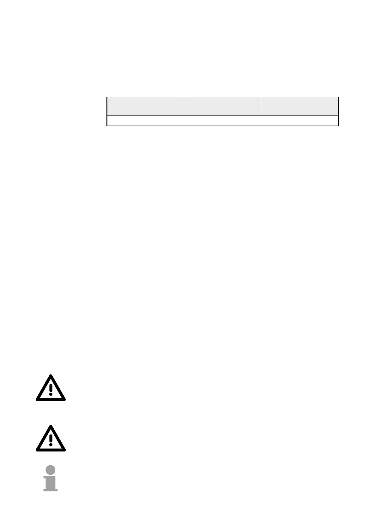
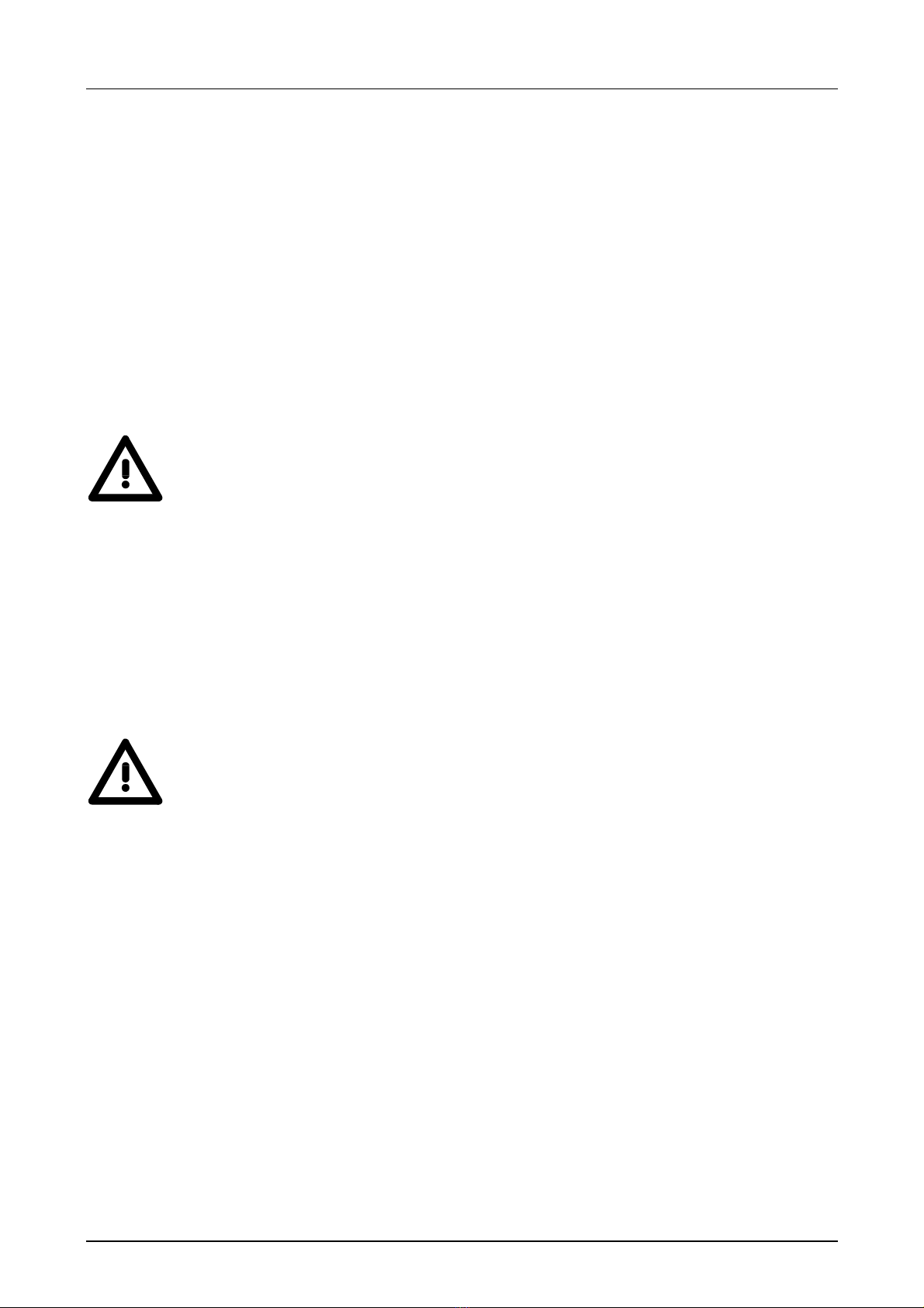
Installation dimensions
Make sure that a clearance of at least 100mm exists above and 70mm
below the middle of the bus rail.
100 mm
70 mm
64 mm
138 mm
150 mm
86 mm
127 mm
89 mm
132 mm
Dimensions
Dimensions
assembled

Chapter 1 Assembly and installation guidelines Manual VIPA TM
1-4 HB39E - TM - RE_900-2C610 - Rev. 13/28
Assembly
The modules are installed on a profile rail. You may use the following
standard 35mm profile rail:
35 mm
27 mm
15 mm
1,5 mm
35 mm
27 mm
7,5 mm
1 mm
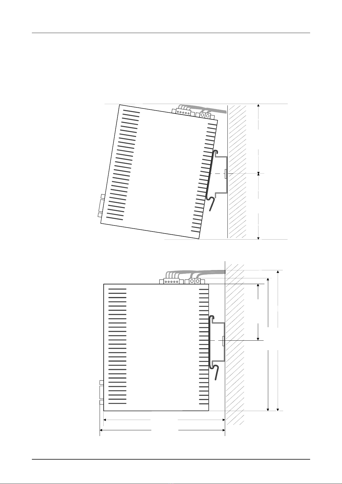
The following sequence represents the assembly procedure as viewed
from the side.
• Install the profile rail. Make sure that a clearance of at least 100mm
exists above and 70mm below the middle of the profile rail.
100 mm
70 mm
Clack
• Insert the module that you are installing into the profile rail at an angle
of about 45 degrees from the top and rotate the module into place until
it clicks into the profile rail with an audible click.
General
Assembly
procedure
Manual VIPA TM Chapter 1 Assembly and installation guidelines
HB39E - TM - RE_900-2C610 - Rev. 13/28 1-5
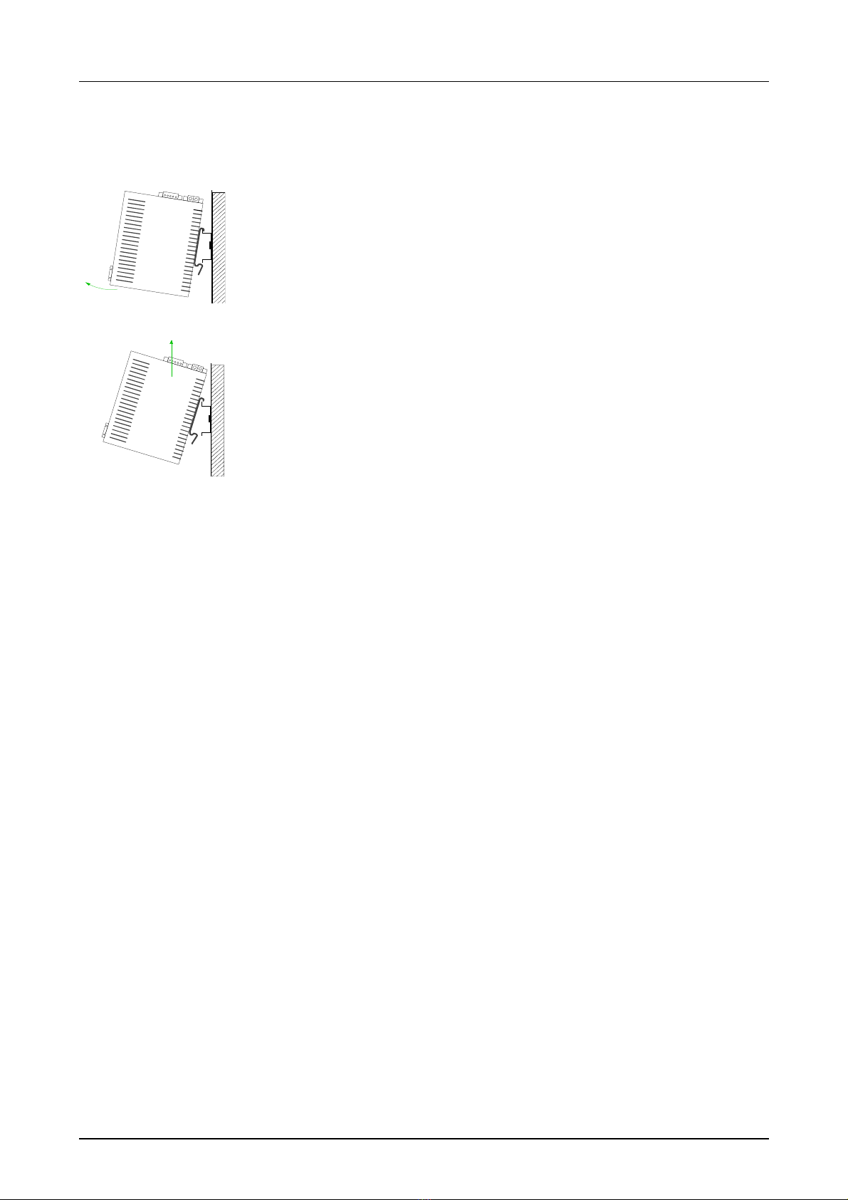
The following sequence shows the steps required for the removal of
modules in a side view.
• For the removal take the module at the bottom and pull it forward
with a strong jerk.
• Now withdraw the module with a slight rotation to the top.
Removal
procedure
Chapter 1 Assembly and installation guidelines Manual VIPA TM
1-6 HB39E - TM - RE_900-2C610 - Rev. 13/28
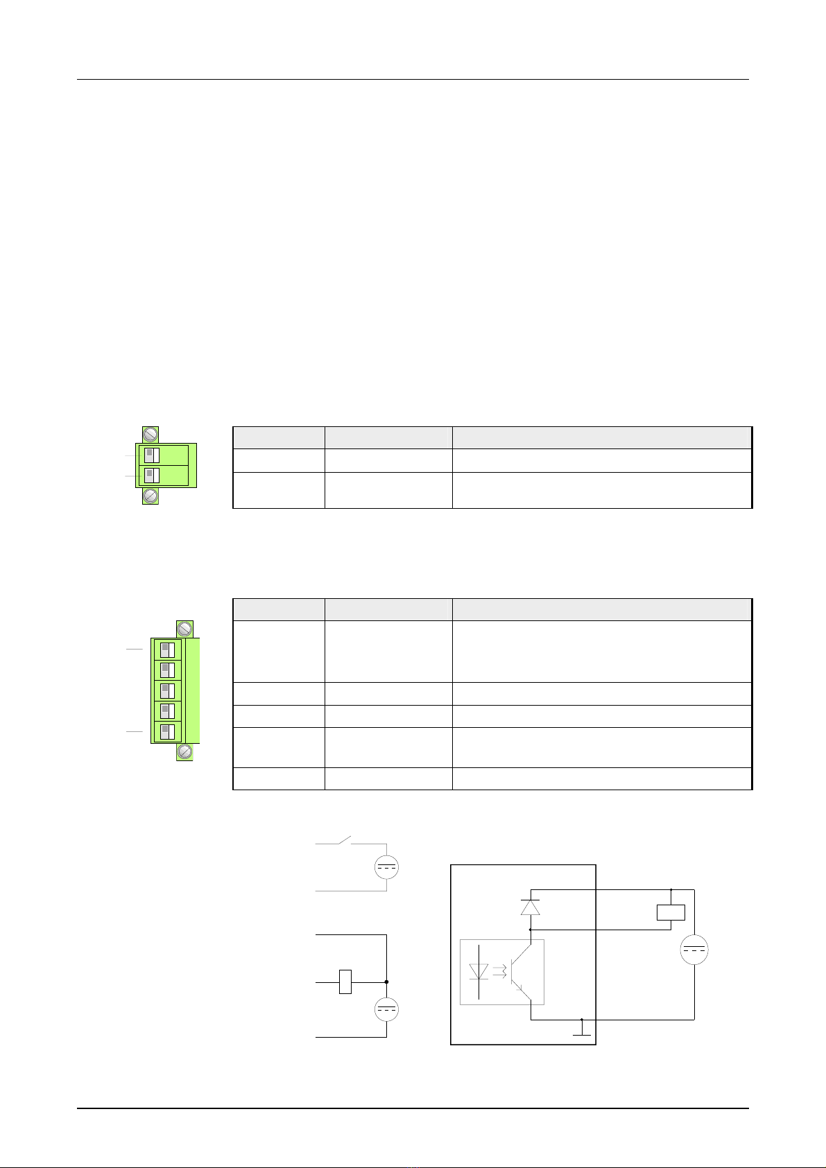
Cabling
At the upper side of the Teleservice module there are connectors for power
supply and digital inputs/outputs. The output is designed as low-side output
and may be configured.
The connectors are plugs with screw contacts. If connected the plugs may
be fixed with screws.
The I/Os are controlled by Tags. An example may be found at the chapter
"Deployment" at "Deployment of Tags".
The Teleservice module is to be supplied by DC 12...24V ±20%.
Pin Name Meaning
2 12-24V DC DC 12 ... 24V ±20%
2
1
1 GND Ground power supply
The output is designed as low-side output and may be configured.
Pin Name Meaning
5 DI Digital input DC 0/24V
"0": 0 ... 5V DC
"1": 10V ... 30V DC
4 DI_GND DI ground (isolated)
3 DO_VDC DO load voltage DC 24V
2 DO Digital output DC 24V, 0.2A
Low-side output
5
.
.
.
1
1 DO_GND DO ground
DC
24V
DO 2
-
+
DC
24V
-
+
DI 5
DI_GND 4
DO_VDC 3
DO_GND 1
DC 24
V
Output DO
Optocoupler
DO_GND
1
DO_OC
2
DO_VDC
3
+
-
Overview
Power supply
DI/DO connection
DI/DO wiring
schematic
diagram

Manual VIPA TM Chapter 1 Assembly and installation guidelines
HB39E - TM - RE_900-2C610 - Rev. 13/28 1-7
Installation guidelines
The installation guidelines contain information about the possible
interference causes. Here we describe possible ways of interference that
may disturb the controlling system and how you have to approach shielding
and screening issues to ensure the electromagnetic compatibility (EMC).
Electromagnetic digestibility (EMC) means the ability of an electrical
device, to function error free in an electromagnetic environment without
being interferenced res. without interferencing the environment.
The Teleservice module is developed for applications in harsh industrial
environments and they comply with EMC requirements to a large degree.
In spite of this you should implement an EMC strategy before installing
your SPS and the Teleservice module, which should include any possible
source of interference.
Electromagnetic interferences may interfere your control via different ways:
• Fields
• I/O signal conductors
• Bus system
• Current supply
• Protected earth conductor
Depending on the spreading medium (lead bound or lead free) and the
distance to the interference cause, interferences to your control occur by
means of different coupling mechanisms.
One differs:
• galvanic coupling
• capacitive coupling
• inductive coupling
• radiant coupling
General
What is EMC?
Possible
interference
causes

Chapter 1 Assembly and installation guidelines Manual VIPA TM
1-8 HB39E - TM - RE_900-2C610 - Rev. 13/28
In the most times it is enough to take care of some elementary rules to
guarantee the EMC. Please regard the following basic rules when installing
your PLC.
• Take care of a correct area-wide grounding of the inactive metal parts
when installing your components.
- Install a central connection between the ground and the protected
earth conductor system.
- Connect all inactive metal extensive and impedance-low.
- Please try not to use aluminum parts. Aluminum is easily oxidizing
and is therefore less suitable for grounding.
• When cabling, take care of the correct line routing.
- Organize your cabling in line groups (high voltage, current supply,
signal and data lines).
- Always lay your high voltage lines and signal res. data lines in
separate channels or bundles.
- Route the signal and data lines as near as possible beside ground
areas (e.g. suspension bars, metal rails, tin cabinet).
• Proof the correct fixing of the lead isolation.
- Data lines must be laid isolated.
- Analog lines must be laid isolated. When transmitting signals with
small amplitudes the one sided laying of the isolation may be
favorable.
- Lay the line isolation extensively on an isolation/protected earth con-
ductor rail directly after the cabinet entry and fix the isolation with
cable clamps.
- Make sure that the isolation/protected earth conductor rail is
connected impedance-low with the cabinet.
- Use metallic or metalized plug cases for isolated data lines.
• In special use cases you should appoint special EMC actions.
- Wire all inductivities with erase links, which are addressed by your
PLC.
- For lightening cabinets you should prefer incandescent lamps and
avoid luminescent lamps.
• Create a homogeneous reference potential and ground all electrical
operating supplies when possible.
- Please take care for the targeted employment of the grounding
actions. The grounding of the PLC is a protection and functionality
activity.
- Connect installation parts and cabinets with your PLC in star topology
with the isolation/protected earth conductor system. So you avoid
ground loops.
- If potential differences between installation parts and cabinets occur,
lay sufficiently dimensioned potential compensation lines.
Basic rules for
EMC

Manual VIPA TM Chapter 1 Assembly and installation guidelines
HB39E - TM - RE_900-2C610 - Rev. 13/28 1-9
Electrical, magnetic and electromagnetic interference fields are weakened
by means of an isolation, one talks of absorption.
Via the isolation rail, that is connected conductive with the rack,
interference currents are shunt via cable isolation to the ground. Hereby
you have to make sure, that the connection to the protected earth conduc-
tor is impedance-low, because otherwise the interference currents may
appear as interference cause.
When isolating cables you have to regard the following:
• If possible, use only cables with isolation tangle.
• The hiding power of the isolation should be higher than 80%.
• Normally you should always lay the isolation of cables on both sides.
Only by means of the both-sided connection of the isolation you achieve
high quality interference suppression in the higher frequency area.
Only as exception you may also lay the isolation one-sided. Then you
only achieve the absorption of the lower frequencies. A one-sided
isolation connection may be convenient, if:
- the conduction of a potential compensating line is not possible
- analog signals (some mV res. µA) are transferred
- foil isolations (static isolations) are used.
• With data lines always use metallic or metalized plugs for serial
couplings. Fix the isolation of the data line at the plug rack. Do not lay
the isolation on the PIN 1 of the plug bar!
• At stationary operation it is convenient to strip the insulated cable
interruption free and lay it on the isolation/protected earth conductor line.
• To fix the isolation tangles use cable clamps out of metal. The clamps
must clasp the isolation extensively and have well contact.
• Lay the isolation on an isolation rail directly after the entry of the cable in
the cabinet. Lead the isolation further on to the PLC and don't lay it on
there again!
Please regard at installation!
At potential differences between the grounding points, there may be a
compensation current via the isolation connected at both sides.
Remedy: Potential compensation line
Isolation of
conductors

Chapter 1 Assembly and installation guidelines Manual VIPA TM
1-10 HB39E - TM - RE_900-2C610 - Rev. 13/28

Manual VIPA TM Chapter 2 Hardware description
HB39E - TM - RE_900-2C610 - Rev. 13/28 2-1
Chapter 2 Hardware description
Here the hardware components of the Teleservice module (TM) are more
described.
The technical data are at the end of this chapter.
Topic Page
Chapter 2 Hardware description ..................................................... 2-1
Properties............................................................................................. 2-2
Structure .............................................................................................. 2-3
Technical Data ..................................................................................... 2-8
Overview
Content
Chapter 2 Hardware description Manual VIPA TM
2-2 HB39E - TM - RE_900-2C610 - Rev. 13/28
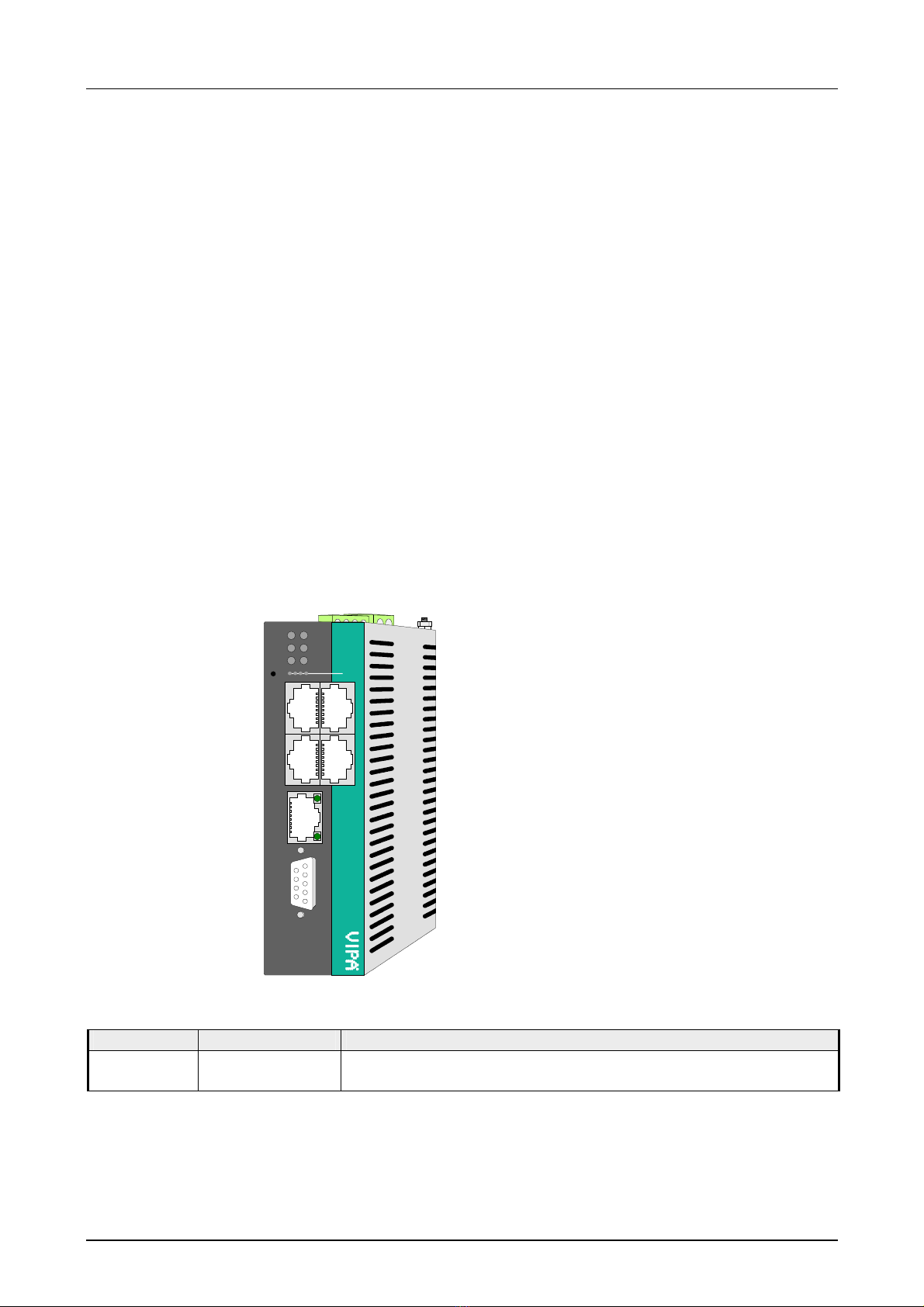
Properties
The TM-C is an intelligent teleservice module with integrated broadband
router. This module makes simple and safe communication with your
machines and plants possible via a DSL connection or in the local network.
Values of your plant may be observed and appropriate reactions to limit
exceeds may be configured. Due to the integrated Web page, for
configuration there is no additional software necessary.
Due to the predefined server the embedding to a VIPA PLC may be
established problem-free. The TM may be integrated as PG/OP interface to
the Siemens SIMATIC manager by means of a station file.
• 4port Ethernet switch for LAN machine network
• 1port Ethernet WAN for LAN factory network
• Broadband router in a compact design
• Sending alarms by eMail and SMS (only via free SMS provider)
• up to 20 Ethernet sessions simultaneous
• RS485 MPI/PROFIBUS DP interface
ETHERNET 2
MPI
900-2C610
TM-C
MACHINE LAN
13
42
LINK/ACT
4 3 2 1
Talk2M
PWR
MPI
KEY
USER
INTERNET
Talk2M
Type Order number Description
TM-C Router VIPA 900-2C610 DC 12 ... 24V, MPI, 5xEthernet RJ45, Router functions,
DI 1xDC 24V, DO 1xDC 24V 0.2A
Overview
Properties
Order data
Table of contents
Other VIPA Network Router manuals


Popular Network Router manuals by other brands

Digi
Digi TransPort WR21 Installation, operation and maintenance

TP-Link
TP-Link TL-R480T+ user guide

Blueone Technology
Blueone Technology HJ8400 Web Configuration User Manual

Paradyne
Paradyne Hotwire 7995 Quick installation instructions

Xiaomi
Xiaomi Mesh System AX3000 user manual

TRENDnet
TRENDnet TEW-823DRU user guide


