VIPA 900-2C5x0 Series User manual

TM | 900-2C5x0 | Manual
HB39 | TM | 900-2C5x0 | GB | 16-03
VIPA Networking Solutions
TM-C Router

900-2C5x0_000_TM-C Router,1,GB - © 2016
VIPA GmbH
Ohmstr. 4
91074 Herzogenaurach
Telephone: +49 9132 744-0
Fax: +49 9132 744-1864
Email: [email protected]
Internet: www.vipa.com

Table of contents
1 General...................................................................................... 4
1.1 Copyright © VIPA GmbH ................................................... 4
1.2 About this manual.............................................................. 5
1.3 Safety information.............................................................. 6
2 Product Summary.................................................................... 8
2.1 Introduction........................................................................ 8
2.2 Concept of the VIPA TM-C Family..................................... 8
2.3 Type and Part Numbers..................................................... 8
2.4 General specification of the hardware platform.................. 9
2.5 Typical applications............................................................ 9
3 Safety, Environmental & Regulatory Information............... 10
3.1 Scope............................................................................... 10
3.2 Power supply.................................................................... 10
3.3 Applicable Directives, Standards and Compliance.......... 10
3.4 Field implementation & environmental conditions............ 11
3.5 Battery.............................................................................. 14
4 Hardware description............................................................ 15
4.1 Mechanical dimensions.................................................... 15
4.2 Overall description........................................................... 16
4.3 Radio communication models.......................................... 20
4.4 LAN Switch Specifications............................................... 22
5 TM-C IP Address & Access to the Web Configuration....... 23
5.1 Factory Default IP settings............................................... 23
5.2 Powering ON.................................................................... 23
5.3 Setting the TM-C LAN IP Address................................... 23
5.4 TM-C Web Interface......................................................... 25
6 Troubleshooting..................................................................... 27
6.1 Normal Boot Process....................................................... 27
6.2 Resetting the TM-C.......................................................... 27
6.3 First Level Reset (user reset)........................................... 27
6.4 Second Level Reset (factory reset).................................. 27
6.5 Reset Impact Matrix......................................................... 28
VIPA Networking Solutions Table of contents
HB39 | TM | 900-2C5x0 | GB | 16-03 3

1 General
1.1 Copyright © VIPA GmbH
This document contains proprietary information of VIPA and is not to
be disclosed or used except in accordance with applicable agree-
ments.
This material is protected by the copyright laws. It may not be repro-
duced, distributed, or altered in any fashion by any entity (either
internal or external to VIPA), except in accordance with applicable
agreements, contracts or licensing, without the express written con-
sent of VIPA and the business management owner of the material.
For permission to reproduce or distribute, please contact: VIPA,
Gesellschaft für Visualisierung und Prozessautomatisierung mbH
Ohmstraße 4, D-91074 Herzogenaurach, Germany
Tel.: +49 9132 744 -0
Fax.: +49 9132 744-1864
EMail: [email protected]
http://www.vipa.com
Every effort has been made to ensure that the information
contained in this document was complete and accurate at
the time of publishing. Nevertheless, the authors retain the
right to modify the information.
This customer document describes all the hardware units
and functions known at the present time. Descriptions may
be included for units which are not present at the customer
site. The exact scope of delivery is described in the
respective purchase contract.
Hereby, VIPA GmbH declares that the products and systems are in
compliance with the essential requirements and other relevant provi-
sions. Conformity is indicated by the CE marking affixed to the
product.
For more information regarding CE marking and Declaration of Con-
formity (DoC), please contact your local VIPA customer service
organization.
All Rights Reserved
CE Conformity Declara-
tion
Conformity Information
VIPA Networking SolutionsGeneral
Copyright © VIPA GmbH
HB39 | TM | 900-2C5x0 | GB | 16-03 4

VIPA, SLIO, System 100V, System 200V, System 300V, System
300S, System 400V, System 500S and Commander Compact are
registered trademarks of VIPA Gesellschaft für Visualisierung und
Prozessautomatisierung mbH.
SPEED7 is a registered trademark of profichip GmbH.
SIMATIC, STEP, SINEC, TIA Portal, S7-300 and S7-400 are regis-
tered trademarks of Siemens AG.
Microsoft and Windows are registered trademarks of Microsoft Inc.,
USA.
Portable Document Format (PDF) and Postscript are registered trade-
marks of Adobe Systems, Inc.
All other trademarks, logos and service or product marks specified
herein are owned by their respective companies.
Contact your local VIPA Customer Service Organization representa-
tive if you wish to report errors or questions regarding the contents of
this document. If you are unable to locate a customer service centre,
contact VIPA as follows:
VIPA GmbH, Ohmstraße 4, 91074 Herzogenaurach, Germany
Telefax: +49 9132 744-1204
EMail: [email protected]
Contact your local VIPA Customer Service Organization representa-
tive if you encounter problems with the product or have questions
regarding the product. If you are unable to locate a customer service
centre, contact VIPA as follows:
VIPA GmbH, Ohmstraße 4, 91074 Herzogenaurach, Germany
Tel.: +49 9132 744-1150 (Hotline)
EMail: [email protected]
1.2 About this manual
This manual describes the Teleservice module 900-2C5x0 from VIPA.
It contains a description of the structure, project engineering and
deployment.
Product Order number as of state:
TM-FW
TM-C Router 900-2C5x0 9.0
The manual is targeted at users who have a background in automa-
tion technology.
The manual consists of chapters. Every chapter provides a self-con-
tained description of a specific topic.
Trademarks
Information product
support
Technical support
Objective and contents
Target audience
Structure of the manual
VIPA Networking Solutions General
About this manual
HB39 | TM | 900-2C5x0 | GB | 16-03 5

The following guides are available in the manual:
nAn overall table of contents at the beginning of the manual
nReferences with page numbers
The manual is available in:
nprinted form, on paper
nin electronic form as PDF-file (Adobe Acrobat Reader)
Important passages in the text are highlighted by following icons and
headings:
DANGER!
Immediate or likely danger. Personal injury is possible.
CAUTION!
Damages to property is likely if these warnings are not
heeded.
Supplementary information and useful tips.
1.3 Safety information
The Teleservice module is constructed and produced for:
ncommunication and process control
nindustrial applications
noperation within the environmental conditions specified in the
technical data
ninstallation into a cubicle
DANGER!
This device is not certified for applications in
– in explosive environments (EX-zone)
The manual must be available to all personnel in the
nproject design department
ninstallation department
ncommissioning
noperation
Guide to the document
Availability
Icons Headings
Applications con-
forming with specifica-
tions
Documentation
VIPA Networking SolutionsGeneral
Safety information
HB39 | TM | 900-2C5x0 | GB | 16-03 6

CAUTION!
The following conditions must be met before using or
commissioning the components described in this
manual:
– Hardware modifications to the process control system
should only be carried out when the system has been
disconnected from power!
– Installation and hardware modifications only by prop-
erly trained personnel.
– The national rules and regulations of the respective
country must be satisfied (installation, safety, EMC ...)
National rules and regulations apply to the disposal of the unit!
Disposal
VIPA Networking Solutions General
Safety information
HB39 | TM | 900-2C5x0 | GB | 16-03 7

2 Product Summary
2.1 Introduction
The present Installation Guide describes the hardware of the VIPA
TM-C family. The VIPA TM-C family is a set of 3 industrial gateways/
routers. The TM-C is fully compatible with the Talk2M cloud connec-
tivity services (www.talk2M.com).
2.2 Concept of the VIPA TM-C Family
The TM-C is available in 3 different versions depending on their com-
munication interface:
2.3 Type and Part Numbers
Part Number Type Description
900-2C510 TM-C VPN Router WAN/LAN
900-2C520 TM-C VPN Router WIFI/WAN/LAN (Antenna included in delivery)
900-2C580 TM-C VPN Router 3G+/WAN/LAN (Antenna 900-0AB51 optional)
900-0AB51 TM-Antenna GSM/GPRS/UMTS
VIPA Networking SolutionsProduct Summary
Type and Part Numbers
HB39 | TM | 900-2C5x0 | GB | 16-03 8

2.4 General specification of the hardware platform
Characteristic Value
Design Industrial design (24 VDC power supply, DIN
Rail mounting, extended temperature)
Processor ARM9
Clock Backed up real time clock (RTC)
Backup battery lifetime has 10 years expect-
ancy
Ethernet Interface LAN Ethernet port 10/100 Mbps
Digital Input 2
Digital Output 1
Mounting Latch for DIN rail EN50022-compliant
2.5 Typical applications
nRemote Access of Ethernet devices using Talk2M connection
nIndustrial VPN router
VIPA Networking Solutions Product Summary
Typical applications
HB39 | TM | 900-2C5x0 | GB | 16-03 9

3 Safety, Environmental & Regulatory Information
3.1 Scope
The present heading addresses Safety, Environmental & Regulatory
Information for the VIPA TM-C family.
3.2 Power supply
The external power supply is a third party device that is not part of
this certification. The device shall be supplied by a LPS power supply
certified according to IEC/UL60950-1 or Class 2 per NEC.
Ä
‘Specifi-
cation of the External Power Supply’ on page 20
3.3 Applicable Directives, Standards and Compliance
The product described in the present Installation Guide complies with
the CE, R&TTE directives and the FCC regulations related to the
wireless modems. The product described in the present Installation
Guide belongs to class A Information Technology Equipment (ITE). In
a domestic environment this product may cause radio interference in
which case the user may be required to take appropriate measures.
The product described in the present Installation Guide is in con-
formity with the following EC directives:
nRoHS Directive 2011/65/EU
nEMC Directive 2004/108/EC
nR&TTE Directive 1999/5/EC (for versions including RF modems)
The product conforms to the corresponding R&TTE articles: RF
spectrum efficiency (Art 3.2); EMC (Art. 3.1b); Safety (Art. 3.1a)
nREACH Directive 2006/121/EC
nFor TM-C 3G+ only: to comply with R&TTE directive
– Antenna must be mounted on a grounded plate
– RFI suppressors must be mounted on the power supply cable
in the following order, starting at 3cm of the connector and
going to the power supply:
Würth Elektronik 742-717-33
Würth Elektronik 742-716-22
Würth Elektronik 742-711-11
The product described in the present Installation Guide is in con-
formity with the following safety standards:
nIEC/EN 60950-1
nUL 60950-1
nCSA-C22.2 No 60950-1-07
The product described in the present Installation Guide complies with
Part 15 of the FCC Rules. Operating is subject to the following two
conditions:
nThis device may not cause harmful interference, and
nThis device must accept any interference received, including inter-
ference that may cause undesired operation.
Applicable European
Directives
Applicable Safety
Standards
FCC Compliance
VIPA Networking SolutionsSafety, Environmental & Regulatory Information
Applicable Directives, Standards and Compliance
HB39 | TM | 900-2C5x0 | GB | 16-03 10

The product described in the present Installation Guide has been cer-
tified by authorized bodies:
nUL Certificate Of Compliance (CoC) for Ordinaty Locations #
E350576 for a TMRA of 60°C
nCB certificate # DK-42240-UL
These certificates can be downloaded as PDF files on:
http://www.vipa.com/en/product/anr/900-2C5x0
3.4 Field implementation & environmental conditions
The VIPA TM-C has an IP20 protection grade. Therefore, the VIPA
TM-C is NOT suited for outdoor mounting. It has to be integrated in
an electrical cabinet, protected from excessive heat, humidity and
dust. Do not push any sharp object into the air vents or openings of
the equipment.
The normal mounting position of the VIPA TM-C is wall mounted on a
horizontal Omega type DIN-rail (EN 50022).
1. Pull the slide lock (located at the bottom of the unit's back-side)
downwards and present the unit in front of the DIN rail.
2. Tilt the TM-C upwards in order to hang it on the upper edge of
the DIN rail by its hook.
3. Gently tilt the unit downwards until it finds its original position.
4. Pull the slide lock upwards to fix and lock the unit on the DIN
rail.
1. Release the unit by pulling the slide lock downwards while
gently tilting the unit upwards.
2. Free the unit by unhooking it from the upper rail edge.
The product is intended to be mounted vertically, label on the right
side.
Certifications
Ingress Protection
Mounting Recommen-
dations
Mounting the unit on
DIN-rail
Removing the unit from
DIN-rail
VIPA Networking Solutions Safety, Environmental & Regulatory Information
Field implementation & environmental conditions
HB39 | TM | 900-2C5x0 | GB | 16-03 11

1 SIM card slot
2 DIN rail mounting bracket
3 Screw holes intended to receive M4 screws with an 8mm diameter
head
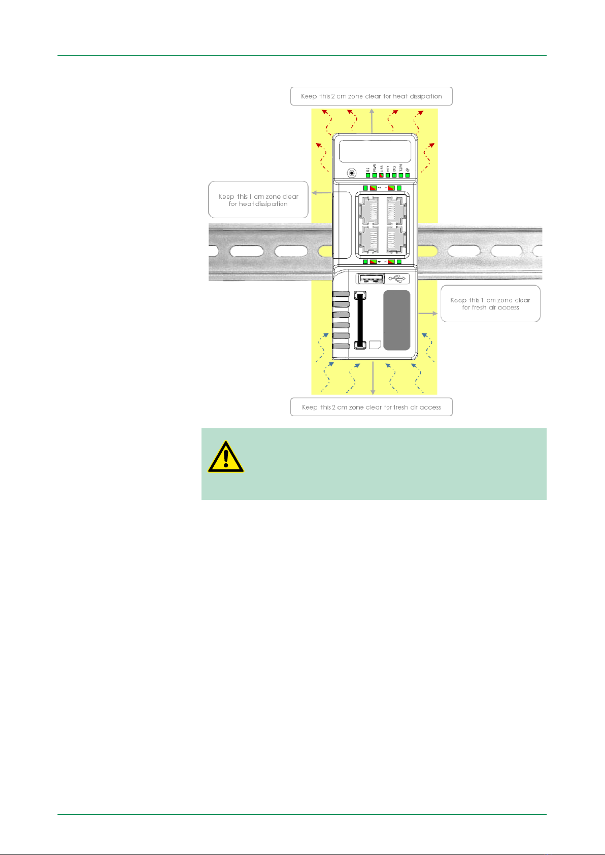
To ensure a proper ventilation of the equipment, a free gap of at least
2 cm must be respected in front of all upper & lower ventilation open-
ings of the unit. A free gap of at least 1 cm must be respected on
each side of the unit.
VIPA Networking Solutions
Safety, Environmental & Regulatory Information
Field implementation & environmental conditions
HB39 | TM | 900-2C5x0 | GB | 16-03 12
CAUTION!
In any other mounting position than the one explained
here above, the specified temperature has to be derated to
-25°C to +40°C.
Shielded cables must be used for Ethernet and USB connectivity to
comply with the EMC requirements. USB cable must be
nshorter than 3m
nUSB 2.0 type
nMaximum current per contact: 0.5A (or better)
n"A" plug connected to the TM-C
Cabling rules
VIPA Networking Solutions Safety, Environmental & Regulatory Information
Field implementation & environmental conditions
HB39 | TM | 900-2C5x0 | GB | 16-03 13

The equipment will operate properly within the following environ-
mental limits if it has been correctly mounted according to the above
mentioned recommendations:
Operating T° -25°C to +70°C
Relative Humidity 10 to 95% non-condensing
Operating altitude Up to maximum 2000m
Storage temperature -40 to +70 °C
Storage Humidity 10 to 95% non-condensing
Storage altitude Up to maximum 3000m
Earthing the TM-C is necessary to eliminate unwanted transients
(lightning protection) and to conform to the EMC requirements. There-
fore, a functional earth (FE) terminal is available on the main con-
nector
Ä
‘Specification of the External Power Supply’ on page 20.
Connect this terminal directly to allow impedance ground. Shielded
cables have to be used for Ethernet and USB to comply with the EMC
requirements.
3.5 Battery
The TM-C contains a CR2032 battery. This battery is used to main-
tain the real time clock upto-date even when the unit is not powered.
CAUTION!
Risk of explosion if battery is replaced by an incorrect
type.
The battery is not attended to be replaced on consumer's
side. The product shall be returned to manufacture for
replacement.
Environmental condi-
tions
Earthing
VIPA Networking SolutionsSafety, Environmental & Regulatory Information
Battery
HB39 | TM | 900-2C5x0 | GB | 16-03 14
4 Hardware description
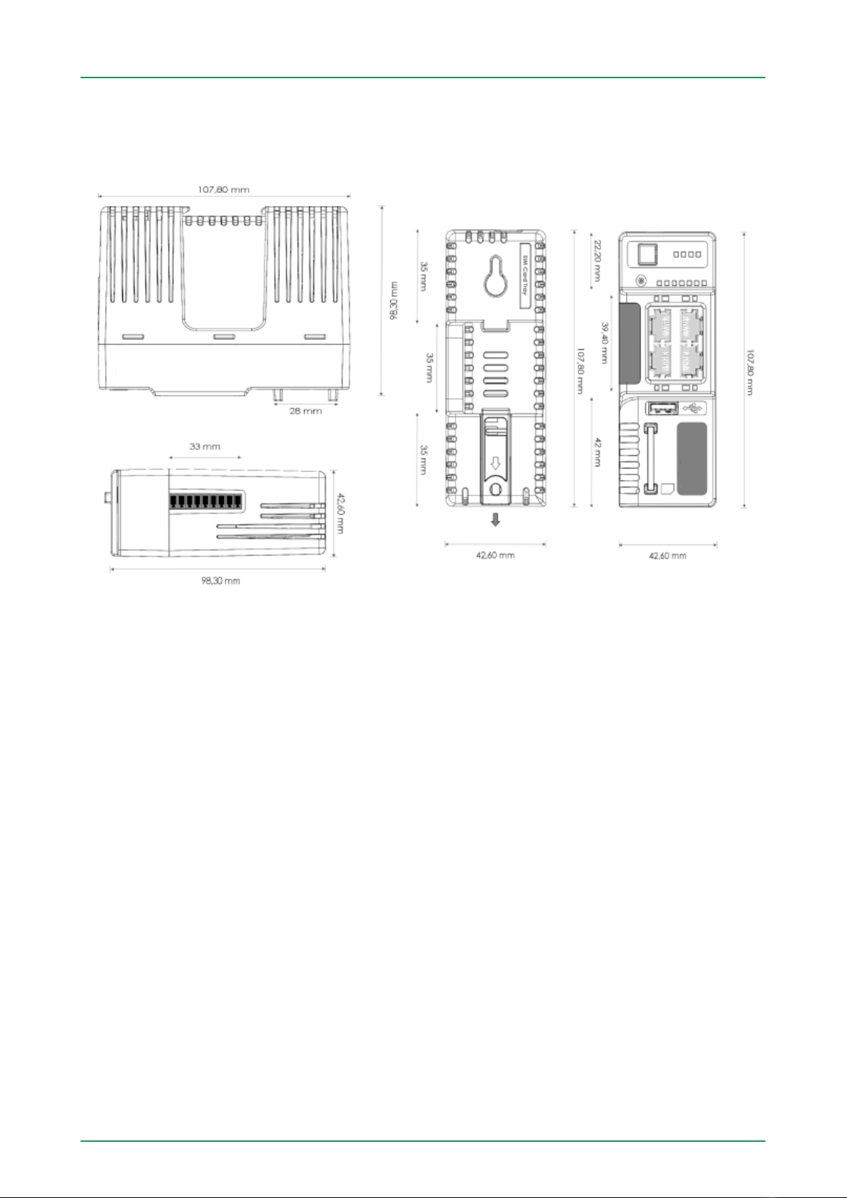
4.1 Mechanical dimensions
VIPA Networking Solutions Hardware description
Mechanical dimensions
HB39 | TM | 900-2C5x0 | GB | 16-03 15
4.2 Overall description
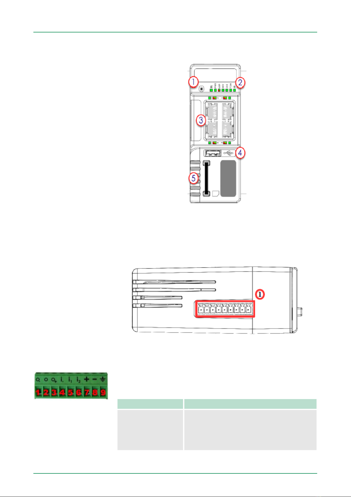
1 Reset button
2 Status LEDs panel
3 LAN/WAN Ethernet ports and corresponding status LEDs (Red:
WAN / Green: LAN)
4 USB slot
5 SD card slot
1 Main connector including power input terminal, 1 DO and 2 DI
As shown in the picture, the female mating connector is labelled with
the appropriate symbols.
Characteristic Value
Connector type MINICONNEC MC model
Type MC 1,5/9-ST-3,5
Pitch = 3.50 mm
9-pin female
Front
Upper side
Main Connector
VIPA Networking SolutionsHardware description
Overall description
HB39 | TM | 900-2C5x0 | GB | 16-03 16
PIN ICON ID Description
1 O- DO_COM Output signal (0V ground)
connected to the emitter of the
MOSFET transistor
2 O DO Output signal
connected to the drain of the
MOSFET transistor
3 O+ DO_VDC Common of the external predrive
power supply
(12 - 24 VDC)
4 i- DI_COM Ground of the input (isolated)
5 i1DI1 Input signal 1
6 i2DI2 Input signal 2
7 + Power in VDD + 12 - 24 VDC
8 - Power in GND - 0V
9 Functional Earth
Characteristic Value
Type of digital output * Open drain MOSFET
Max. current (ext,source) 200 mA
Isolation (both DI & DO) 1.5 kV
DI voltage range 0 to 24 VDC
DI protection 33 VDC Max
DI OFF state input voltage range 0 to 5 VDC
DI ON state input voltage range 10 to 30 VDC
DI ON state current range From 3.8 mA @ 12 VDC to 8,2
mA @ 24 VDC
*) When the TM-C reboots, a short phase of ON state is part of the
starting process.
The digital output is activated by an open drain MOSFET transistor
driven by an optocoupler. The maximum current flow inside this tran-
sistor has a value above the one specified in the TM, in order to cope
with the switching power losses. The transistor used is in an open
drain type with predrive. This means the relay power supply has to be
supplied from an external source to the predrive electronics. The dia-
gram below shows the external wiring needed for proper operation of
the digital output. A relay has been chosen for this sample application
but any load within the specifications can be used instead.
This is a sink only output to ground (the transistor acts like
a switch ground).
Digital Output and Dig-
ital Inputs
VIPA Networking Solutions Hardware description
Overall description
HB39 | TM | 900-2C5x0 | GB | 16-03 17

Digital Output & Inputs can be used on the TM-C, some features can
be externalized by wiring the main connector.
LED Connector Description
KEY DI1 On a key switch to authorize or prevent the
Internet connection.
On a key switch to authorize or prevent the
VPN connection.
DI2 DI2 Not supported.
T2M DO Can be wired to an external device to propa-
gate the Talk2M status.
If the VPN connection is active, the DO is set
to 1.
Digital Input (DI1) can be used as a connectivity condition.
The configuration of this condition has to be done during the Internet
Wizard where you define if the digital input is used or not and for
which purpose.
Possible features
VIPA Networking SolutionsHardware description
Overall description
HB39 | TM | 900-2C5x0 | GB | 16-03 18

Label Description
BI1 Button BI1 input
Green ON = Reset being pressed
PWR Power
Green ON = Power is present
USR User
Green ON+OFF slowly = Unit is OK RED pattern =
special attention required
KEY Digital IN 1 - Green = ON: Signal on input 1
detected
DI2 Digital IN 2 - Green = ON: Signal on input 2
detected
T2M Talk2M - Green ON = Talk2M VPN connection
established
@ Internet
Green ON = Internet is configured on the VIPA
TM-C
1 SMA male connector for WiFi antenna
2 Modem status Green ON = WiFi connected
3 Reception signal level Red ON = Poor signal
4 Reception signal level Red ON = Signal is OK
5 Reception signal level Red ON = Good signal
Status LED panel (All
version)
Status LED panel (TM-C
- WiFi)
VIPA Networking Solutions Hardware description
Overall description
HB39 | TM | 900-2C5x0 | GB | 16-03 19

1 SMA female connector for GSM antenna
2 Modem status Green ON = Modem connected
3 Reception signal level Red ON = Poor signal
4 Reception signal level Red ON = Signal is OK
5 Reception signal level Red ON = Good signal
The TM-C must be powered by a safety Low Power Supply (LPS) in
accordance with clause 2.5 of UL/IEC 60950-1 Ed2. Standard,
12-24VDC, 30W min. Certified for 60°C and for altitudes up to 2000m.
The safety LPS power supply is not part of the delivery.
Characteristic Value
Power supply voltage external 12-24 VDC +/- 19%
Max TM input power 30W max.
Internal voltage protection max 30V
Input protection protected against polarity inver-
sion
4.3 Radio communication models
CAUTION!
This device is intended to be used in fixed or mobile appli-
cations only (not for portable applications). The antenna
used for this transmitter has to be installed in a space pro-
viding a safe distance of at least 20 cm without encoun-
tering any person and must not be co-located or operating
in conjunction with any other antenna or transmitter.
Item Value(s)
Protocols and Frequencies IEEE802.11b/g/n, 2.4GHz - Channels: 1 to 11(inclusive)
Antenna Connector Type RP-SMA
Antenna
(included in the delivery)
Characteristic Value(s)
Impedance 50 Ohms
Status LED panel (TM-C
- 3G+)
Specification of the
External Power Supply
TM-C with internal WiFi
modem
VIPA Networking SolutionsHardware description
Radio communication models
HB39 | TM | 900-2C5x0 | GB | 16-03 20
This manual suits for next models
5
Table of contents
Other VIPA Network Router manuals


