Visionhitech VC58FHD User manual

1
Version 1.1.0
Release Date : Feb. 24, 2011
Full HD CCTV Box camera
I
IN
NS
ST
TR
RU
UC
CT
TI
IO
ON
N
M
MA
AN
NU
UA
AL
L
Model : VC58FHD
Power option
z12VDC
z12VDC/24VAC
2
Version 1.1.0
Release Date : Feb. 24, 2011
Dear Customers!
By selecting this product, you have decided to use a professional device that guarantees
highest quality and reliability. We would like to thank you very much for your confidence and
kindly ask you to read the following instructions carefully before Installation and operation in
order to take full advantage of all quality features regarding this product.
The lighting flash with an arrowhead symbol, within an equilateral
triangle is intended to alert the user to the presence of uninsulated
dangerous voltage within the product’s enclosure that may be of
sufficient magnitude to constitute a risk of electric shock to persons.
The exclamation point within an equilateral triangle is intended to alert
the user to the presence of important operating and maintenance
(servicing) instructions in the literature accompanying the appliance.
INFORMATION - This equipment has been tested and found to comply with limits for a
Class A digital device, pursuant to part 15 of the FCC Rules. These limits
are designed to provide reasonable protection against harmful
interference when the equipment is operated in a commercial
environment. This equipment generates, uses, and can radiate radio
frequency energy and, if not installed and used in accordance with the
instruction manual, may cause harmful interference to radio
communications. Operation of this equipment in a residential area is
likely to cause harmful interference in which case the user will be
required to correct the interference at his own expense.
WARNING – Changes or modifications not expressly approved by the manufacturer
could void the user’s authority to operate the equipment.
CAUTION – To prevent electric shock and risk of the fire hazards:
Do NOT use power source other than that specified.
Do NOT expose this appliance to rain or moisture.
CAUTION
RISK OF ELECTRIC
SHOCK
CAUTION
TO REDUCE THE RISK OF ELECTRIC SHOCK,
DO NOT REMOVE THE COVER (OR BACK)
This installation should be made by a qualified service person and should conform to
all local codes.

3
Version 1.1.0
Release Date : Feb. 24, 2011
Table of contents
1. Precautions ------------------------------------------------------------------------------------------------------ 4
2. Limitation of liability ------------------------------------------------------------------------------------------ 5
3. Disclaimer of warranty --------------------------------------------------------------------------------------- 5
4. Package ----------------------------------------------------------------------------------------------------------- 6
5. Name and function of each part --------------------------------------------------------------------- 7 ~ 8
6. Installation ------------------------------------------------------------------------------------------------ 9 ~ 11
6-1. Lens
6-2. When using an auto iris lens (DC- drive)
6-3. When using a C-Mount Lens
6-4. When using a CS-Mount Lens
6-5. Application of HD-SDI output
6-6. Power
7. Function and operation ----------------------------------------------------------------------------- 12 ~ 19
7-1.On Screen Menu(OSD)
7-2. Setting up the menu
7-3. VIDEO OUT
7-4. AUTO MENU
7-5. DAY/NIGHT
7-6. AWB
7-7. AE
7-8. PRIVACY
7-9. EFFECT
7-10. SYSTEM
7-11. INITIALIZE
7-12. EXIT
8. Trouble shooting guide ------------------------------------------------------------------------------------ 20
9. Dimension ------------------------------------------------------------------------------------------------------ 21
10. Specification ------------------------------------------------------------------------------------------ 21 ~ 22

4
Version 1.1.0
Release Date : Feb. 24, 2011
1. Precautions
· Please read the manual carefully before the installation in order to make use the
camera to be set up correctly and to have the best picture quality.
· Please keep the manual in good condition for your future reference and service
application.
· Installation and services should only be carried out by an authorized personnel
according to local safety regulations.
· If any liquid or solid matter gets into the housing, immediately disconnect the camera
from power supply and have it checked by your authorized dealer before reusing.
· Avoid installing the camera at extremely hot or cold places.
· If you are not a certified person, never try to dismantle the camera. To avoid electric
shock, never remove the screws or covers. There are no parts inside that need
maintenance by the user. All maintenance should be carried out by qualified
personnel.
· Avoid installing the camera at a place of high humidity.
· Avoid installing the camera at the place exposed to gas or oil.
· Keep the top glass of the lens always clean in order to obtain the best picture quality
all the time. Be careful not to be stained by fingerprint.
· Don't face the camera directly toward sunlight or sunlight reflecting area.
The sensor may go defective at this condition.
· Please give a special attention to keep the unit from dangerous drop or
external shock during the process of transportation or handling.
· Never try to touch the camera in wet hand. It may cause an electric shock.
· Do not expose the camera to radioactivity. It causes a serious damage on the sensor.
5
Version 1.1.0
Release Date : Feb. 24, 2011
2. Limitation of liability
This publication is provided “AS IS” without warranty of any kind, either express or implied,
including but not limited to, the implied warranties of merchantability, fitness for any particular
purpose, or non-infringement of the third party's right. This publication could include technical
inaccuracies or typographical errors. Changes are added to the information herein, at any time,
for the improvements of this publication and/or the corresponding product(s).
3. Disclaimer of warranty
In no event shall seller be liable to any party or any person, except for replacement or
reasonable maintenance of the product, for the cases, including but not limited to below :
(1) Any damage and loss, including without limitation, direct or indirect, special,
consequential or exemplary, arising out of or relating to the product;
(2) Personal injury or any damage caused by inappropriate use or negligent operation
of the user;
(3) Unauthorized disassemble, repair or modification of the product by the user;
(4) Inconvenience or any loss arising when images are not displayed, due to any reason
or cause including any failure or problem of the product;
(5) Any problem, consequential inconvenience, or loss or damage, arising out of the
system combined by the devices of third party.
(6) Any claim or action for damages, brought by any person or organization being
photogenic subject, due to violation of privacy with the result of that surveillance-
camera's picture, including saved data, for some reason, becomes public or is used
for the purpose other than surveillance.
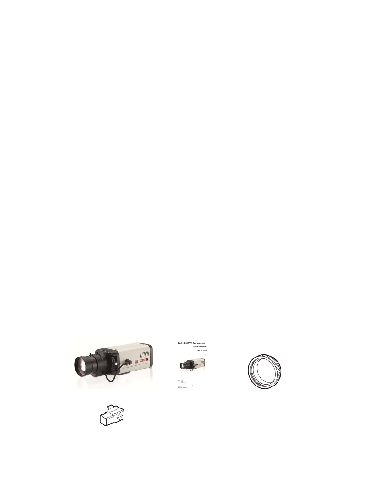
4. Package contents
Full HD CCTV Box Camera 1EA Instruction Manual 1EA C-Mount Adaptor
Auto Iris Plug 1EA
6
Version 1.1.0
Release Date : Feb. 24, 2011
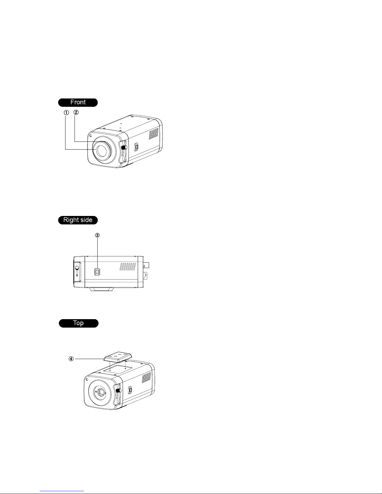
5. Name and function of each part
Protective cover①
C②-Mount lens adaptor
③DC Iris Jack for DC Auto Iris Lens
④Mounting bracket holder
Mounting bracket holder can be
separated and attached on the
bottom side as well.
Please use the supplied clamp
screws only to change the position
of the bracket. Using screws more
than 5mm depth can cause a serious
damage to the inside of this camera.

7
Version 1.1.0
Release Date : Feb. 24, 2011
⑤OSD Control button
⑥Power indicator LED
Lamp is on when the power is being
supplied.
⑦CVBS output (BNC Female)
Connect coaxial cable for composite
video signal out.
⑧HD-SDI output (BNC Female)
Connect coaxial cable for HD-SDI signal
video signal out.
NOTE : HD-SDI and CVBS output can be
used simultaneously
⑨RS-485 Control port
You can control SETUP menu
through this port by using external
controllers like a remote controller
that RS-485 Communication is
supported. For details, see page 20.
⑩Day & Night Out port
This unit can be synchronized by an
External IR LED kit through this port.
Low : CDS sensor off ( LED off)
High : CDS sensor On ( LED on)
⑪Power input terminal
Connect to the power source.
Polarity of the power is self-
configured. (Non-polarity).
8
Version 1.1.0
Release Date : Feb. 24, 2011
6. Installation
6-1. Lens
Lens is not supplied with the unit. C-Mount or CS-Mount type of lens is available.
Please select a lens that has a good F-Stop number in order to get the best picture quality.
Use of DC auto iris lens is recommended to achieve the best results for operating this product
effectively.
☞Caution
Please make sure the surface of the lens is always clear. Clean dirt or water drops with soft
cloth in order to avoid the picture blooming or reflection.
☞NOTE
To get the best image quality, please use recommended lenses from the manufacturer or
camera supplier.
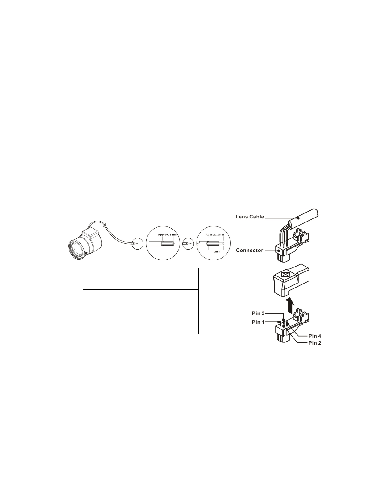
6-2. When using an auto iris lens (DC-drive)
1. Please take off the sleeve outer cable of the lens by 10mm.
2. Please take off the sleeve inner cable of the lens by 2mm.
3. Solder the wires on the pin-connector (iris-jack) supplied with the lens according to the pin
configuration as shown in the drawing.
4. Assemble the lens.
5. Connect the Auto Iris jack.
Pin No. Lens
DC
No.1 Pin Damping -
No.2 Pin Damping +
No.3 Pin Drive +
No.4 Pin Drive -

9
Version 1.1.0
Release Date : Feb. 24, 2011
6-3. When using a C-mount Lens
Please assemble C-Mount adaptor.
C-Mount adaptor is included in the package.
Fix the lens by turning it clockwise.
6-4. When using a CS-mount Lens
Take off the Protection cover.
Take off the C-MOUNT adaptor.
Assemble the CS-MOUNT lens by turning it clockwise.
- When used with an Auto Iris lens, please insert the
iris jack into the Iris socket which is located on the
right side of the camera.
- Please set the lens mode by using OSD Switch on
the back of the camera depending on the type of
selected lens.
☞Caution
- Use the lens as shown in the picture here.
- When the lens is out of the spec, it could damage the camera inside
or may not be correctly fit with the camera.
- Use the lens less than 450g. Heavier lens can damage the camera.

10
Version 1.1.0
Release Date : Feb. 24, 2011
6-5. Application of HD-SDI output
Impedance alliance in the system connection.
Make sure to connect the cable with the power off. Please locate the impedance switches of
each equipment as instructed. Locate the switch to Hi-z position for the interim equipments.
Locate the switch to 75for the last equipment.
6-6. Power
12VDC camera
Please make sure to use a UL/CE approved and
12VDC/450mA regulated power supply.
12VDC/24VAC Dual Power camera (Option)
Please make sure to use a UL/CE approved and
12VDC/450mA, 24VAC/220mA regulated power
supply.

11
Version 1.1.0
Release Date : Feb. 24, 2011
7. Function and operation
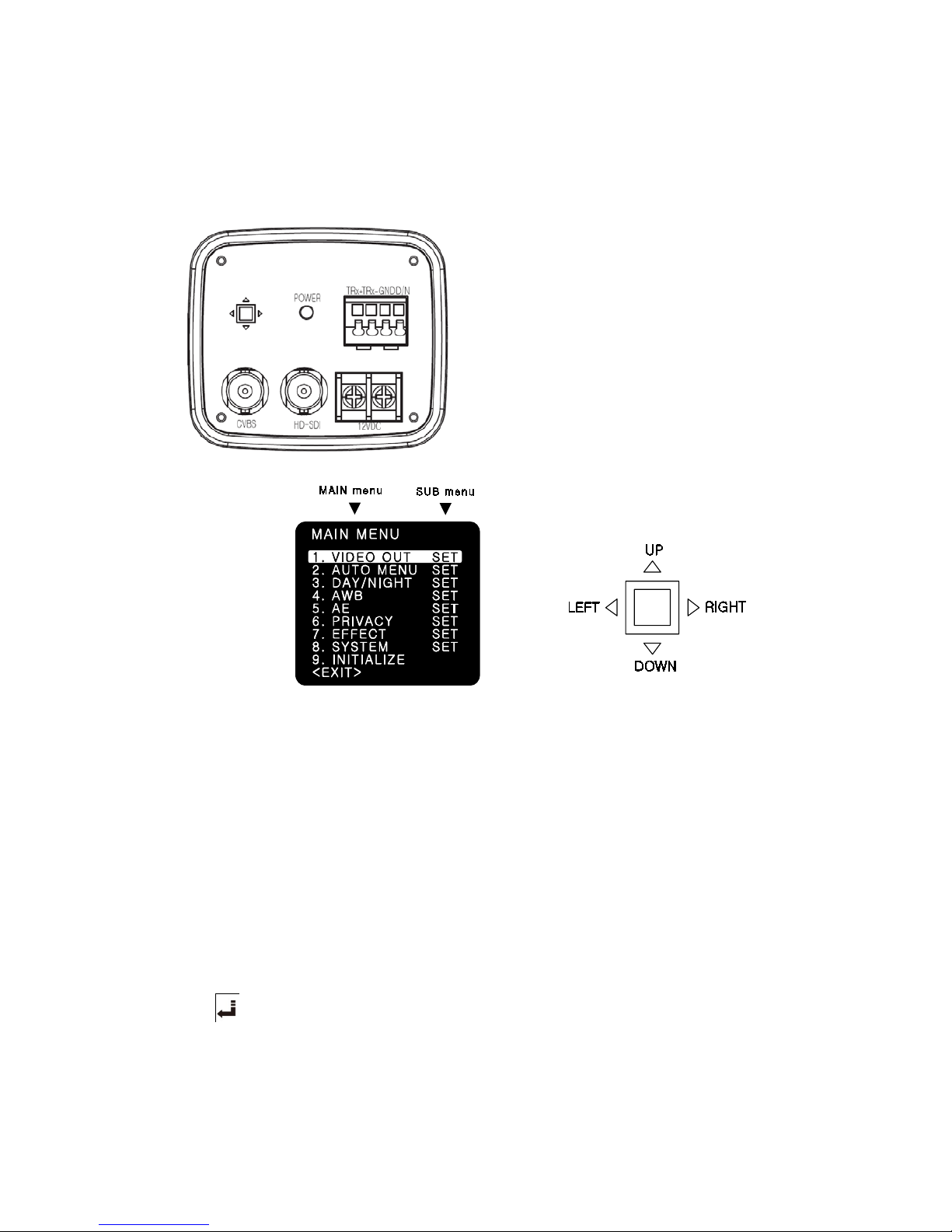
7-1. On Screen Menu
MAIN MENU
VIDEO OUT VIDEO OUTSIZE FRAME RATE CVBS OUT MODE SAVE/
RETURN
AUTO MENU NORMAL 50HZ INDOOR 60HZ INDOOR OUTDOOR RETURN
DAY/NIGHT AUTO/COLOR/IR D TO N LEVEL
N TO D LEVEL
D TO N TIME
N TO D TIME
D/N RESET RETURN
AWB (ATW)/PUSH/HOLD
TRACK/USER/8000K/
6000K/4200K/3200K
RED BLUE AWB RESET
RETURN
AE IRIS
ATR-EX(WDR)
DSS
DC IRIS
BLC/FLC
BRIGHTNESS
LSC
FLICKERLESS
AGC
AE RESET
RETURN
PRIVACY AREA NUMBER
MASK POSITION
MASK DEFINE
PRIVACY RESET
MASK PATTERN MASK SIZE RETURN
EFFECT COLOR ADJUST
2DNR
SHARPNESS
3DNR
CONTRAST
EFFECT RESET
REVERSAL
RETURN
SYSTEM CAMERA ID
FIRMWARE
ID DISPLAY
485 TERM
CAMERA NAME
BAUD RATE
NAME DISPLAY
SYSTEM RESET
RETURN
INITIALIZE FACTORY INIT RETURN
EXIT SAVE/EXIT EXIT RETURN
12
Version 1.1.0
Release Date : Feb. 24, 2011
7-2. Setting up the menu
Settings can be made using the OSD Switch located on the back of the camera.
1. Press the button to access the SETUP mode.
The SETUP menu is displayed on the
monitor.
2. Please select any function you wish to
activate by using the UP/DOWN selections.
The cursor can be moved up or down by
using the UP/DOWN selections.
Position the cursor to point to the function
you wish to operate.
* MAIN-menu : Use UP/ DOWN selections. / SUB-menu : Use LEFT/ RIGHT selection
3. Change the status of the selected feature using the LEFT/RIGHT selections.
When the LEFT or RIGHT selection is done, available values and modes are displayed in
order.
Please keep the selection until you get to the mode you wish to operate.
4. When completed, move the cursor indicator to ‘EXIT’ position and press the Button to finish
the setting.
☞NOTE
If appears at the mode you wish to operate, it means that there is a sub-menu which
can be selected by OSD Switch.
13
Version 1.1.0
Release Date : Feb. 24, 2011
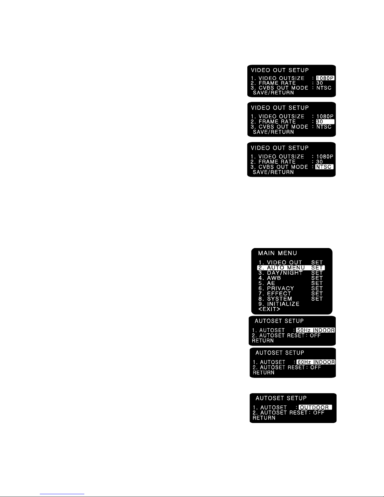
7-3. VIDEO OUT
(1) VIDEO OUTSIZE
- VIDEO OUTSIZE can be set to 1080P, 1080i, 720P according
to Local Regulation.
(2) FRAME RATE
- Six modes of 60/59.94/50/30/29.97/25 can be selected.
(3) CVBS OUT MODE
- CVBS output can be set to NTSC or PAL according to
local TV standard.
☞NOTE
In case of 1080i mode, only 3 types of Frame rate are available and they are 60/50/59.94
respectively.
When you use 1080P 60 mode, please check your DVR or related HD devices first whether
they support this mode or not. ( In this mode, cable connection distance is less than half of
1080P 30 mode.)
7-4. AUTO MENU SET
(1) NORMAL
- Sets as initial factory default value.
(2) 50HZ INDOOR
- For indoor use in 50HZ (PAL) environment.
(In this mode, i.e. 50HZ INDOOR MODE, FLICKERLESS changes
automatically into 50HZ mode from initial OFF mode.)
(3) 60HZ INDOOR
- For indoor use in 50HZ (PAL) environment.
(In this mode, i.e. 60HZ INDOOR MODE, FLICKERLESS changes
automatically into 60HZ mode from initial OFF mode.)
(4) OUTDOOR
- For outdoor use.
(In this mode, i.e. OUTDOOR MODE, AWB changes
automatically into PUSH mode from initial ATW mode.)
14
Version 1.1.0
Release Date : Feb. 24, 2011
(5) AUTOSET RESET
- When set as ON and press SET KEY, it turns into AUTOSET NORMAL MODE
automatically, which means initial factory reset.
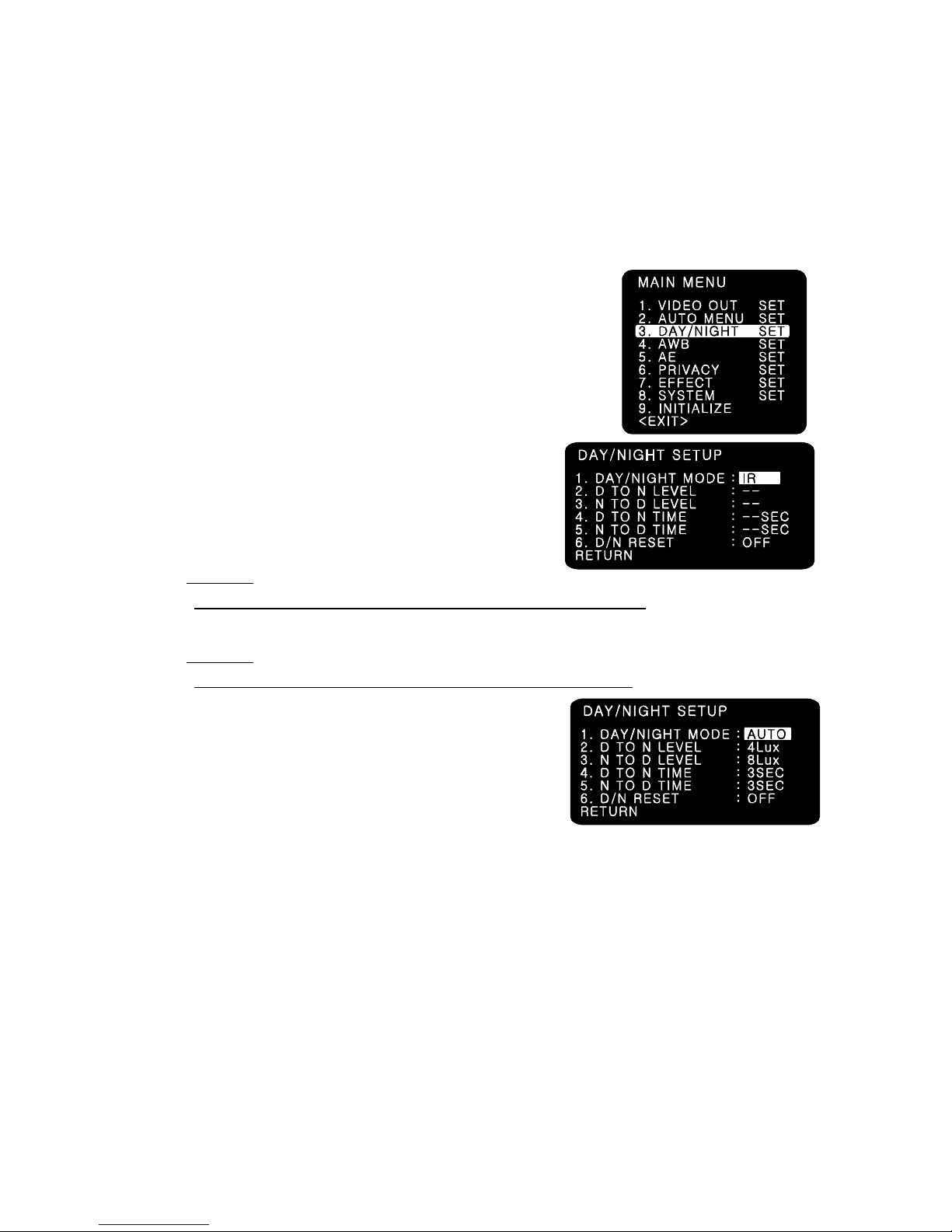
7-5. DAY/NIGHT
You can display pictures in Color/IR MODE/AUTO.
(1) DAY/NIGHT MODE
1. Please position the cursor on ‘DAY/NIGHT’ on the
SETUP menu by using the UP and DOWN selections.
2. Please select the mode you wish to operate by using the
LEFT and RIGHT selections.
- COLOR : The picture is always displayed in color.
- IR : The mode is switched to ‘DAY’ in a normal
environment, but switches into ‘NIGHT’ mode when
ambient illumination is low.
☞NOTE
True Day & Night cameras with CDS & ICR are to be set in this mode.
- AUTO: Automatically turns between Day and Night Mode according to AGC operation.
☞NOTE
Day & Night cameras without CDS & ICR are to be set in this mode.
(2) D TO N LEVEL
- Sets the level of illumination in which COLOR mode
is turned into B/W mode.
(This menu is not activated in case of IR MODE)
(3) N TO D LEVEL
- Sets the level of illumination in which B/W mode is turned into COLOR mode.
(This menu is not activated in case of IR MODE)
(4) D TO N TIME
- Sets the switching time from COLOR mode into B/W mode when the level of illumination has
come to D TO N LEVEL.
(Not activated in case of IR MODE)
(5) N TO D TIME
- Sets the switching time from B/W mode into COLOR mode when the level of illumination has
come to N TO D LEVEL.
(Not activated in case of IR MODE)
15
Version 1.1.0
Release Date : Feb. 24, 2011
(6) D/N RESET
- Resets all setting of DAY/NIGHT menu into initial factory default value.
(7) RETURN
- Returns to the MAIN MENU.
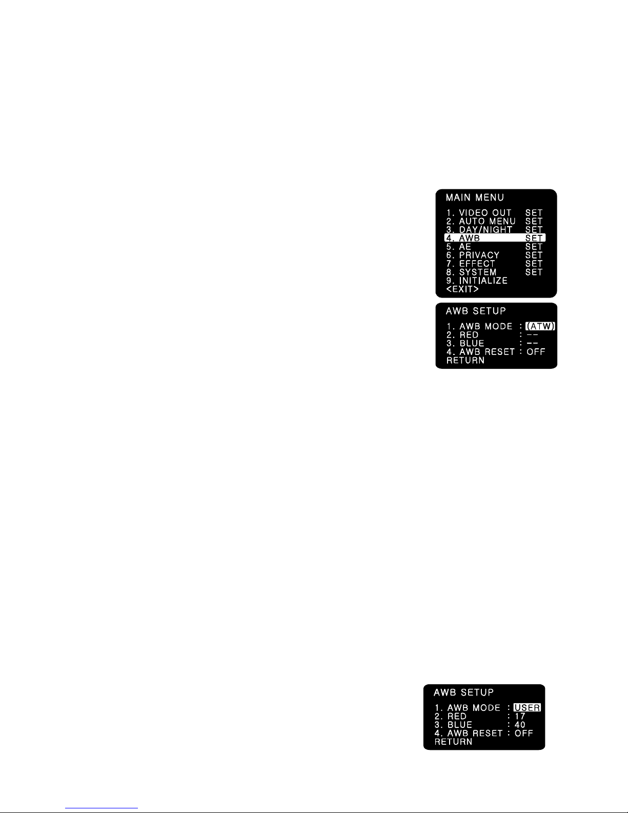
7-6. AWB (Auto White Balance)
This is useful when the cameras are installed in different artificial
lighting conditions where a standard ‘White Balance’ condition is
not suitable for all.
(1) AWB MODE
1. Please position the cursor on ‘AWB’ on the
SETUP menu by using the UP and DOWN selections.
2. Please select the mode you wish to operate by using the
LEFT or RIGHT selection.
3. Please select one of the 8 modes below.
(2) ATW (Auto Tracking White Balance)
- IN : This mode can be used within the color temperature range of 2,500˚K~7000˚K.
- OUT : This mode can be used within the color temperature range of 1,800˚K~10,500˚K.
☞NOTE : In case of indoor use, ATW(IN) mode is higly recommended.
(3) PUSH MODE : This mode can be used within the color temperature range of
1,800˚K~10,500˚K.
☞NOTE : In case of outdoor use, PUSH mode is recommended.
(4) HOLD MODE : This mode is used to fix AWB in a specific environment.
☞NOTE : When there are drastic movements of some specific colored features such as red,
blue, green or yellow cars on the express road and when environment is volatile so much,
HOLD MODE is strongly rcecommended.
(5) TRACK MODE : Sets some specific range of color temperature. ( 23 types of color
temperature can be set within 1,500˚K~15,000˚K range.)
(6) USER MODE
USER MODE is suitable for enhanced users who want to set red and/or blue value
manually according to user’s environment.
Please change to manual adjustment mode and press OSD Switch.
Set the appropriate color temperature, and then increase or decrease the red and blue
color values while monitoring the color changes on the screen.
- RED : Adjust the level between 00 ~ 50(Default 17)
- BLUE : Adjust the level between 00 ~ 50(Default 40)
16
Version 1.1.0
Release Date : Feb. 24, 2011
(7) 8,000˚K/6,000˚K/4,200˚K/3,200˚K MODE
- 8,000˚K : Shade
- 6,000˚K : Cloudy weather
- 4,200˚K : Fluorescent light
- 3,200˚K : Electric light blub
(8) AWB RESET
- Resets all setting of AWB menu into initial factory reset value.
(9) RETURN
- Returns to the MAIN MENU.
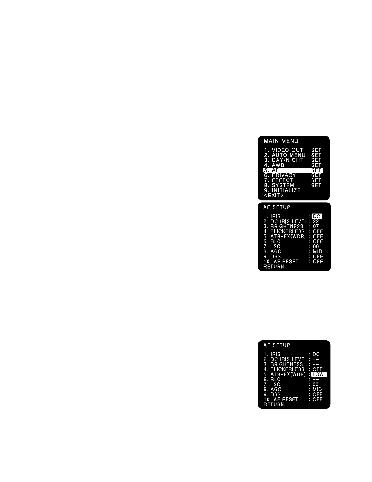
7-7.AE (Auto Exposure)
(1) IRIS MODE
- DC : Selects DC drive auto iris lens.
- ESC : Selects manual iris lens
- AE HOLD : Fixes the change of the brightness.
This mode is useful when lots of motions are detected
on the monitor.
(2) DC IRIS LEVEL : Adjusts the mechanical Iris lens in 00 ~ 50(Default22)
(3) BRIGHTNESS : Adjusts the brightness in 00 ~ 30(Default 07)
(4) FLICKERLESS :
This is used only when there is a difference in frequency between the
power system (50Hz) and TV system (60Hz). In this case, flicker is
occurred on the monitor. In most countries other than Japan, FLICKERLESS mode is not
necessary.
☞NOTE
When the power system (50Hz) and the TV system(60Hz) are different,
-‘Flickerless on’ mode is recommended for indoor use.
-‘Flickerless off’ mode is recommended for outdoor use.
(5)ATR-EX (WDR) : This mode functions like WDR.
3 modes of Off/Low/Mid/High can be selected.
Wide Dynamic Range Performance
In general, it is very hard to see objects inside the buildings, etc
in case that there comes strong light from the outside.
By using ATR-EX(WDR) mode, the difference in brightness between
the bright area and the dark area can be minimized and consequently those objects inside
and outside of the buildings or windows can be seen all together even though there is strong

17
Version 1.1.0
Release Date : Feb. 24, 2011
light or backlight from the outside.
☞NOTE
- This mode is recommended for those environment with backlight or shade.
- When ATR-EX(WDR) is ON, DC IRIS LEVEL, BRIGHTNESS,
BLC menu’s are all inactivated.
(6) BLC (Back Light Compensation)
Enables a user to directly select a desired area from a picture,
and to view the area more clearly even under backlight environment.
- BLC : Used for backlight environment.(Indoor objects can be seen.)
- FLC : Compensates the saturation of image when camera faces
toward the same direction as sunlight.
(7) LSC (Lens Shading Correction) : Adjust the LEVEL 00 ~ 50(Default 00)
Compensates for the shading of the lens.
☞NOTE : This function will be provided soon in next version.
(8) AGC(Auto Gain Control)
The higher the gain level is, the brighter the screen becomes.
But the higher gain level causes more noise.
- LOW : Allows automatic gain control from 0 to 20dB.
- MIDDLE : Allows automatic gain control from 0 to 30dB.
- HIGH : Allows automatic gain control from 0 to 42dB.
(9) DSS(Digital Slow Shutter)
This is an electronically activated function to improve the
sensitivity for viewing low light condition in addition to the original
sensitivity from the sensor itself.
Shutter level is adjustable x2 times.
At night, DSS is set to x2 automatically.
☞NOTE: This function will be provided soon in next version.
(8) AE RESET
- Resets all settings of AE menu into the initial factory default value.
(9) RETURN
- Returns to the MAIN MENU.
7-8.PRIVACY
Masks the areas you want to hide on the screen.

18
Version 1.1.0
Release Date : Feb. 24, 2011
(1) AREA NUMBER: You can select up to 4 PRIVACY areas.
(2) MASK DEFINE: Determines whether to use the MASK or not.
(3) MASK PATTERN: Defines the Mask Color or type.
- 6 types of BLACK/RED/GREEN/BLUE/YELLOR/MOSAIC are selectable.
(4) MASK SIZE: By moving the cursor LEFT/RIGHT, TOP/BOTTOM, the size of masking area
can be determined..
(5) MASK POSITION: Adjust vertical and horizontal position of masking area.
(6) PRIVACY RESET
- Resets all setting of PRIVACY menu.
(7) RETURN
- Returns to the MAIN MENU.
7-9.EFFECT
(1) COLOR ADJUST
- COLOR GAIN : Adjusts the COLOR GAIN level in 00 ~ 50(Default 25)
- COLOR HUE : Adjusts the COLOR HUE level in 00 ~ 50(Default 25)
☞NOTE
This function enables user to adjust the variation of Color Gain
on the monitor when installing camera.
(2) SHARPNESS
- Adjusts the SHARPNESS level in 00 ~ 50(Default 25)
(3)CONTRAST
-Adjusts the CONTRAST level in 00 ~ 50(Default 25)
(4) REVERSAL: Enables either normal image (NORMAL), mirrored
Image ( MIR), vertically reversed image ( VER), vertically
reversed and mirrored image( FLIP).
(5) 2DNR
- Cuts off the noise in low light condition.
4 modes of OFF/LOW/MID/HIGH are available.
☞NOTE
Higher 2DNR level reduces more low light noise but deteriorates resolution as well.
(6) 3DNR
- Cuts off the noise in low light condition.
4 modes of OFF/LOW/MID/HIGH are available.
☞NOTE
Higher 3DNR level reduces more low light noise but it can cause ghost effect as well.
19
Version 1.1.0
Release Date : Feb. 24, 2011
☞NOTE: This function will be provided soon in the next firmware version.
(7) EFFECT RESET
Resets all setting of EFFECT menu into initial factory default.
(6) RETURN
- Returns to the MAIN MENU.
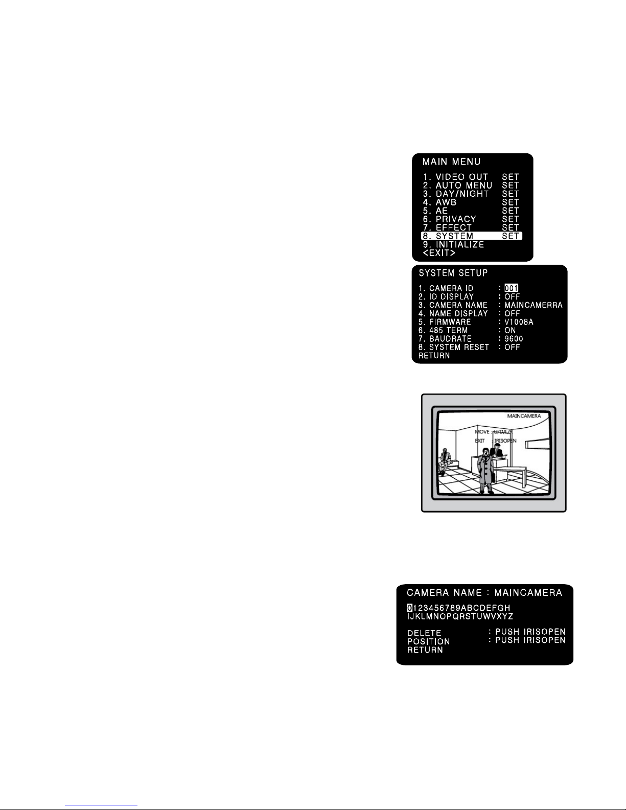
7-10.SYSTEM
(1) CAMERA ID : Determinds the camera ID number in 001 ~ 255
(Default 001)
(2) ID DISPLAY : Defines the location where camera ID is displayed
on the screen. 4 location of top, bottom, left and right can be
selected.
(3) CAMERA NAME
- Defines camera name. When ‘Name Display’ is on, this text will
Be shown on the screen.
(4) NAME DISPLAY
If you enter a title for this, that will appear on the monitor.
1. Please position the cursor on ‘NAME DISPLAY by
moving UP or DOWN direction.
2. Then, select ‘ON’ by using the LEFT and RIGHT selection.
When you press the button to complete ‘ON’, then ‘CAMERA
NAME’ will be displayed.
☞NOTE
· If ‘OFF’ is selected, the NAME DISPLAY does not appear on the monitor even if it has been
input.
3. Up to 10 letters are available for the NAME DISPLAY.
①Please move the cursor to the letter to choose by
using the UP and DOWN selections.
②Set an ID from 0,1,~8,9, A,B, ~Y,Z by
using the UP, DOWN, LEFT and RIGHT selections.
③Lock in the letters by using the button.
When the letter is locked in, the cursor moves to the next space.
④Please repeat the above to input NAME DISPLAY.
20
Version 1.1.0
Release Date : Feb. 24, 2011
4. When a name has been chosen, please select a position for the name to display.
①Please move the cursor onto ’POSITION’ and then press the button.
②The name will appear at the top right corner.
③Please find the position you wish to display the name by using the 4 directional
selections, and then press the button to finish.
5. Camera Name Input process is finished if user selects ‘RETURN’ and presses OSD switch.
(5) FIRMWARE:
- Shows firmware version of this camera unit.
(6) 485 TERM
- RS485 Function ON/OFF
(7) BAUD RATE
- Selects baud rate for RS485 communication among 2400/ 4800/ 9600. (Default:9600)
(8) SYSTEM RESET
- Resets all setting of SYSTEM menu.
CAMERA ID, 485 TERM settings are not initialized.
(9) RETURN
- Returns to the MAIN MENU.
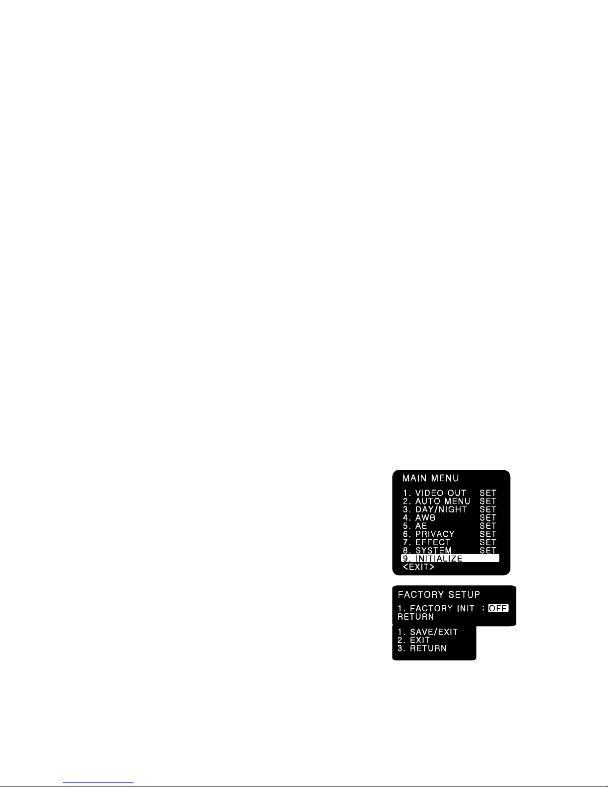
7-11.INITIALIZE
Resets the camera setting to the factory defaults.
CAMERA ID, 485 TERM settings are not initialized.
7-12.EXIT
(1) SAVE/EXIT
- Saves the current settings and exits the menu.
(2) EXIT
- Not saves the current settings and exits the menu.
(3) RETURN
- Returns to the MAIN MENU.
Table of contents


