VitalWell VW1100A User manual

V
V
i
i
t
t
a
a
l
l
W
W
e
e
l
l
l
l
E
E
l
l
e
e
c
c
t
t
r
r
o
o
n
n
i
i
c
c
s
s
P
P
t
t
e
e
L
L
t
t
d
d
.
.
T
T
e
e
l
l
:
:
+
+
8
8
6
6
-
-
0
0
7
7
5
5
6
6
-
-
3
3
8
8
6
6
7
7
2
2
8
8
0
0
BlockD2,#408/409,SouthernSoftwarePark,TangJia,
,
Z
Zh
hu
uH
Ha
ai
i,
,
C
Ch
hi
in
na
a
5
51
19
90
08
80
0
vital-well.com
VW1100A
VW2500A
VW1203A
VW1205A
USER MANUAL Rev. 2.5B)
VitalWell Electronics Pte. Ltd.

V
V
i
i
t
t
a
a
l
l
W
W
e
e
l
l
l
l
E
E
l
l
e
e
c
c
t
t
r
r
o
o
n
n
i
i
c
c
s
s
P
P
t
t
e
e
L
L
t
t
d
d
.
.
T
T
e
e
l
l
:
:
+
+
8
8
6
6
-
-
0
0
7
7
5
5
6
6
-
-
3
3
8
8
6
6
7
7
2
2
8
8
0
0
BlockD2,#408/409,SouthernSoftwarePark,TangJia,
,
Z
Zh
hu
uH
Ha
ai
i,
,
C
Ch
hi
in
na
a
5
51
19
90
08
80
0
vital-well.com
ProprietaryNotice:
CopyrightVitalWell ElectronicsPte.Ltd.,2005
The information inthisdocument issubject tochange without notice.
Companyorproductnamesmentioned inthisdocumentmaybe trademarks or
registeredtrademarks of theirrespectivecompanies.
All rightsreserved.Neitherthe wholenoranypartofthe information contained in
thispublication maybe reproducedinanymaterialformexceptwiththe written
permission of VitalWellElectronics PteLtd..
Thispublication isintended onlytoassistthereaderinthe useoftheproduct.
VitalWellElectronics PteLtd. shallnotbe liableforanyloss ordamage arising
fromthe useofanyinformation inthispublication,oranyerrororomissionin
suchinformation,oranyincorrect useof theproduct.
Technical Support:
Documentation isupdated periodically.Forthelatestinformation aboutVitalWell
Electronics PteLtd.products,including softwareupgradesandapplication
information,pleasecontactyourlocalVitalWell ElectronicsPteLtd.Salesentity.
VitalWellElectronicsPteLtd.providescustomertechnicalsupportusingphone
and/ore-mail means.
Forcustomertechnicalsupport, pleasecontactyourlocalVitalWell Electronics
PteLtd. salesentity.

V
V
i
i
t
t
a
a
l
l
W
W
e
e
l
l
l
l
E
E
l
l
e
e
c
c
t
t
r
r
o
o
n
n
i
i
c
c
s
s
P
P
t
t
e
e
L
L
t
t
d
d
.
.
T
T
e
e
l
l
:
:
+
+
8
8
6
6
-
-
0
0
7
7
5
5
6
6
-
-
3
3
8
8
6
6
7
7
2
2
8
8
0
0
BlockD2,#408/409,SouthernSoftwarePark,TangJia,
,
Z
Zh
hu
uH
Ha
ai
i,
,
C
Ch
hi
in
na
a
5
51
19
90
08
80
0
vital-well.com
INTRODUCTION
The VWseriesRadioModemprovidesthe capabilityofashortrange,reliable
wireless point-to-point, point-to-multipointand meshnetworkRFdata
communicationslink.
The VWseriesmodemcan be used inavarietyofdatacommunications
applicationsthatrequireasimpletouseinvisibledatalink.The radiomodemis
designed tointerfacetoavarietyofhostdevices.Thesedevicesinclude
computers,receiptprinters,PLC s,dataloggers,SCADAdevicesand intelligent
controlsystems.
The serialdatatransferredoverthe radiolinkisnot altered; theoutput serialdata
streamisthe sameasthe inputserialdatastream.The radiomodemsprovide a
two-waydatacommunicationslinks,whereeachunitcanacceptserialdataand
alsooutputserialdata.
The VWseriesradiomodemsarefullyself-containedunits,requiringonlyan
external+5VDC (or+3.3VDC)powersourcetooperate.Theradiomodulesused
inthe radiomodemshavebeen selected tomeetthe requirementsofunlicensed
operationinthe internationalISMbands,and arethereforeacceptableforusein
manycountries.
Features
§4operation modes:Transparentmode,Transparentsecured mode,
Addressed mode and Addressed secured mode
§Repeatersupported
§Deep sleep mode
§Server-Client mode
§Broadcast Multi-drop mode
§Serialprotocolformat is9600bps,8data/1stop/no parity.
§Selectableflowcontrolof software/none.
§Selectableradiospeed,channeland radiopower.
§On-airdataencryption,errorchecking anddataacknowledgements.
§Easy configuration byATcommands.
§Builtinconfiguration anddiagnosticfunctions.
Thismanualdescribestheelectricalspecificationsanddifferentfunctioning
modesavailableon the VWseries.Thisdescription willalsohelpyouto
understand the principlesbehind the configurationregistersandtousethem
moreefficiently.

V
V
i
i
t
t
a
a
l
l
W
W
e
e
l
l
l
l
E
E
l
l
e
e
c
c
t
t
r
r
o
o
n
n
i
i
c
c
s
s
P
P
t
t
e
e
L
L
t
t
d
d
.
.
T
T
e
e
l
l
:
:
+
+
8
8
6
6
-
-
0
0
7
7
5
5
6
6
-
-
3
3
8
8
6
6
7
7
2
2
8
8
0
0
BlockD2,#408/409,SouthernSoftwarePark,TangJia,
,
Z
Zh
hu
uH
Ha
ai
i,
,
C
Ch
hi
in
na
a
5
51
19
90
08
80
0
vital-well.com
CONTENTS
CHAPTERIELECTRICALSPECIFICATION ……………………………1
CHAPTERIICONFIGURATIONMODE ……………………………………3
II.1EnteringConfiguration Mode
II.2Command Format
II.3Configuration CommandsinDetail
II.4RegistersDescription
CHAPTERIIITRANSPARENTMODE ……………………………….……9
III.1Operation
III.2Examples
CHAPTERIVTRANSPARENTSECUREDMODE ……………………… 10
IV.1Operation
IV.2Examples
CHAPTERVADDRESSEDMODE …………………………………………11
V.1Operation
V.2Examples
CHAPTERVIADDRESSEDSECUREDMODE …………… ………… …12
VI.1Operation
VI.2Examples
CHAPTERVII ORDERING INFORMATION ………………………………...13
APPENDIX …………………………………………………………………………...14
A. Modemsand boardsInstallation: Principlesand cautions
B. Registersettingtipsandexamples
B.1. Configuration list file
B.2. Turnon Softwareflowcontrol(Xon/Xoff)
B.3. Changing Operation Mode
B.4. Atypicalpoint-point configuration using Addressed Mode
B.5. AtypicalServer-Client configurationusingAddressed Mode
B.6. AtypicalHyper-terminalsetting (Xon/Xoffenable)

VitalWell ElectronicsPteLtdwww.vital-well.com-1-
CHAPTERIELECTRICALSPECIFICATION
The VWseriesinclude4differentmodels:RS232T,RS232C,RS485/422,
and USB.The radioperformanceisthesameacross all4models.Theyare
named bythe differentinterfaces.
I.1General Specifications
)SupplyVoltage:+5V(±20%)
2)SupplyCurrent:<100mA
3)Voltagelevelat I/O:+3.3V TTL(+5V compatible)
4):SerialInterfaceCharacteristics(RS232)
i.Baud rate:9600, 8N1. (Default)
5)RFCharacteristics:
i.Frequency band:ISM433/868/915MHz/2.4GHz
ii.Channels:16 or255(for2.4GHz)
iii.RFrate:
1.2kbps, 2.4kbpa,4.8kbps,9.6kbps, 19.2kps,
38.4kbps,76.8kbps,
115.2kbps,256kbps(VW1100A/VW2500A)
iv.MaxRFtransmitterpower:
Sub-1G: +10dB; 2.4G : 0dB
v.Sensitivity:-116dB(2.4kbps), -108dB(38.4kbps)
vi.Typicallinkrange (outdoor) :>1000m
I.2Dimension
1)(LXWXH):50mm X25.2mm X8mm (VW1100A, VW2500A)
60mm X26mm X9mm (VW1203A,VW1205A)
2)Interface:9pin;2.0mm header
I.3Interface Specifications
I.3.1:VWxxxxA-232T
TheRS232signalvoltagelevelis3.3VTTLlevelattheinterface,with
+5Vcompatible.
1)SignalDefinitions:
PinNo. SignalName PinNo. SignalName
GND 6I/O1
2VCC (+5V) 7I/O2
3RXD(RS232,TTL) 8I/O3
4TXD(RS232, TTL) 9N.C
5I/O0(Sleep /EN)
VitalWell ElectronicsPteLtdwww.vital-well.com-2-
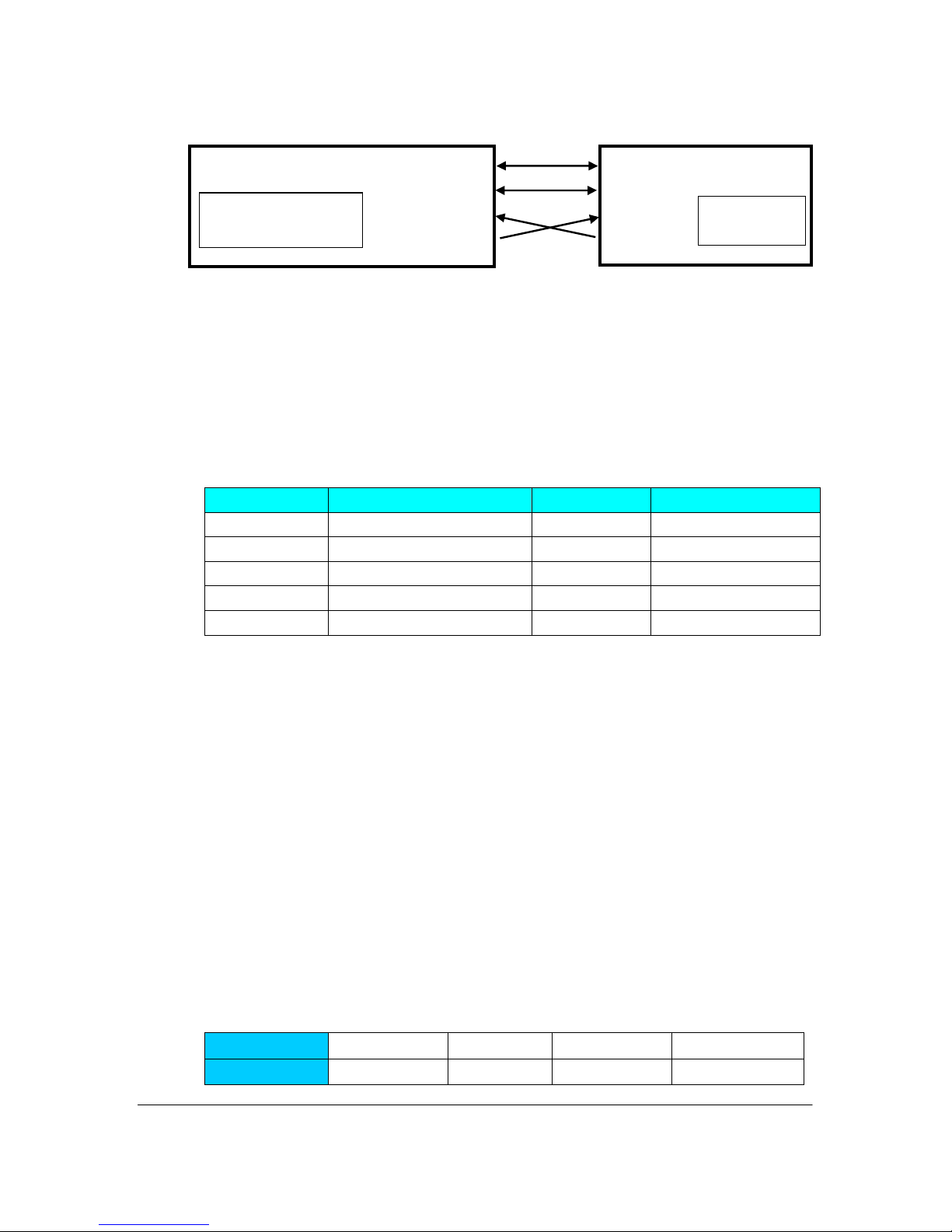
2)TypicalConnections(connectionsat Pin1~4only)
I.3.2:VWxxxxA-232C
Forthe RS232 TXD/RXDsignals,the voltagelevelatthe interface
isRS232Clevel.Theothersignalassignment isthesameasVW-232T.
I.3.3:VWxxxxA-485
SignalDefinitions:
PinNo. SignalName PinNo. SignalName
GND 6TD-
2VCC (+5V) 7I/O2
3RD+ 8I/O3
4RD- 9N.C
5TD+
I.3.4:VWxxxxA-USB
The interfaceisUSB.Itwill takepowerfromtheUSB port.Sono
externalpowersupplyneeds.Afterinstalling adriver,itwillcreatea
virtualserialportonthePC.Allapplications,whichdesigned forserial
ports,will beabletoworkwell withthismodule.E.g.,It allowsthe PCto
useanormalhyper-terminalapplication tocommunicatewiththe module.
Pleasebe noted,dependson theUSB portson the PC,the driver
willautomaticallycreatedifferent “virtual”serialportnumbers.For
example,the PChas4USBports,say,wejustnamethematUSB1,
USB2,USB3,USB4.WhenthemoduleplugsintoUSB1,itmaycreatea
virtualserialport,sayCOM3;WhenthemoduleplugsintoUSB2,itwill
createanothervirtualserialport, sayCOM4; then, COM5, and COM6, etc.
SignalDefinitions:
PinNo. 1 2 3 4
SignalName
+5V DM DP GND
1(GND)
2(+5V)
3(RXD)
4(TXD)
(GND)
2(+5V)
3(RXD)
4(TXD)
RF-VWseriesHost

VitalWell ElectronicsPteLtdwww.vital-well.com-3-
CHAPTERII CONFIGURATIONMODE
Thissection describestheconfiguration andtestcommandssupportedbythe
radiomodem.Inmostcases,oncethe configuration issetitwillnotneed tobe
changed.Configuration isperformed usingaserialterminal,orappropriate
communication application.
Allcommandsand command valuesacceptedbytheradiomodemaredescribed
inthissection;anyentriesotherthanthoselisted hereresultsinaninvalid
command orargument errormessage.
The firststep toconfiguring theRadioModemistoputitinConfiguration Mode…
II.1EnteringConfigurationMode
Aseriesofthree consecutivelytypedcharacters,called anescapesequence,
forcesthe radiomodemtoexitdatatransfermode and enterthe modem
configuration mode.Whilein Configuration Mode,youcancommunicatedirectly
withthe radiomodemusing anumberof specificcommandstoconfigureandtest
the radiomodem.
The escapesequenceisfactorysetto ‘+++ (Nocarriagereturnkeyisfollowed).A
pauselengthofwhichiscalled the escapeguardtime(about1s)mustbe
completed bothbeforeand afterwhen escapesequenceisentered.Thesethree
'+'charactersmust not be sent asone continued frame. The delaybetween any2
charactersmustbe between 20ms~1sforthe (‘+++ )sequence.Thisprevents
the radiomodemfrominterpreting theescape sequenceasdataandthe vice
versa.Theguardtimemustalsobemetwhen the RadioModemisinitially
powered up.
Configurationchangesarestored permanentlyinnon-volatilememorywithinthe
RadioModem.Exiting Configuration Mode and returning back todatatransfer
mode isaccomplishedbytyping ATO”atthe command prompt. Thiswillforcea
soft resetofthe RadioModemresulting inanyconfiguration changestaking
effect.
II.2CommandFormat
VWmodem sparametersaresetthrough theuseofATtype commandssenton
the seriallink.
'AT' commandscomplieswithHayesprotocolused inPSTNmodemstandards.
This ‘AT protocolisused toconfigurethe modemparameters,based onthe
followingprinciples:

VitalWell ElectronicsPteLtdwww.vital-well.com-4-
Adataframealways beginswiththetwoASCII AT characters,standingfor
‘ATtention ,
_Commandsarecoded overoneorseveralcharactersand mayinclude
additionaldata
_Agivencommand always endsup witha<CR>Carriage Return
AT Command Additionaldata <CR>
Note: The delaybetween 2charactersof the samecommand must be less
than 30 seconds
Allalphabeticalcharacterstyped inconfiguration command mode areconverted
touppercasebeforebeing interpreted bythe configurator.Thuscommandscan
be typed using eitherupperorlowercase.
Despiteitssimilaritytostandardtelecommunicationmodem,itremainsaradio
linkmodemand isconsequentlyfittedwithsomeparticularandspecific ‘AT
commandspropertoradiotransmission (I.e.communicationchannel,radio
rate...).

VitalWell ElectronicsPteLtdwww.vital-well.com-5-
II.3 ConfigurationCommandsinDetail
Command Description
Operating mode
+++
ConfigurationMode Activation
+++’Command givesaninstantaccess tothe modem s
parametersconfiguration mode(ATmode).
+++’Command shouldbeent
eredonebyone. The timebetweentwo ‘+
must bebetween10ms~1s.
Answer:>
ATO
Communicationmodeactivation
ATO’commandgivesaninstant accesstothemodem s
Operatingmode.
ATO’commandisusedtoget outofConfigurationMode.
Answer:Good Bye!
Command Description
RegisterHandling
AT/V
AT/V’command displays themodem sfirmwareversion numbersimilar
asfollows:
SignatureReport:
RFModemV2.00A
Built Date&Time:
Jan 52006
21:50:03
>
AT/L
AT/L’commanddisplaysa
dynamicandclearstatusofall relevant
registersof themodemwiththefollowingcategories:
_Seriallink,
_Radio,
_OperationMode,
_Network
ATSn=m
Or
ATSn=m.k
ATSn=m’or ATSn=m.k’commandconfiguresregisternumbernwith
thevaluem(orm.k, if 2Bytes),e.g. ATS100=32<CR> entersthevalue
‘32 intheregisterS100;ATS120=192.168 enterthe value ‘192.168 in
theregisterS120.Thevalueof m& kisbetween0~255.
Answer:> or ??(CR)> if the configurationisnotvalid

VitalWell ElectronicsPteLtdwww.vital-well.com-6-
II.4RegistersDescription
The parameterstobe configured viaConfigurationmode arestoredinmodem s
EEPROM sregisters, called Sregisters. Thoseregistersarealways listed as
follows:
_S10xregisterscorrespond tothe serialparameters,
_S110xregisterscorrespond tothe radioparameters,
_S12xregisterscorrespond tothe general/networkoperationparameters,
The standardregistersandtheiruseareshowninthe next table.

VitalWell ElectronicsPteLtdwww.vital-well.com-7-
II.4.1RegistersDescriptionTable
SerialLink
Access
Registers
Name Description
R/W
S100
SerialLink
FIFO size
Indicatesthemaximumframessizethatwillbe
giventothe Modem.Whenthissizeisreached,
the datainthe FIFOwill be immediatelysentout
viaRFlink(Ifflowcontrolisenable,aXoff code
willbe sent outfrom
the modem).
ValueRange:1~64, Default: 60
R/W
S101
SerialLink
FlowControl
Indicatesflowcontroltype:
_'0':None
(default)
_'1': Software: Xon/Xoff,
R/W
S102
SerialLink
TimeOut
Indicatesthevalueofthe time-outon the seri
al
link(
timeoutcountson byteslapsedon the
currentbaudrate).E.g:
atserialbaudrate
9600bps,avalue ‘5meansa
5bytestransmit
timeon 9600bps,thatis:about5ms.
Thisisused:when the serialFIFOisnotfull,
afterthistimeout, the datain
theFIFOwill be
sent out viaRFlink.
Value Range: 3~255
Default: 5
R/W
S103
SleepMode
Control
SleepModeControl:
0 –Disable(Default), modulealways active
1 –Enable
IfS103=1, themodulewill becontrolledbyI/O0
I/O0= 0:active
I/O0=1: SleepMode(powerdownmode)
And: I/O1(output)will beusedtoindicatethe
working status:
I/O1= 0: indicateaactivestatus
I/O1= 1: indicateapowerdownmode

VitalWell ElectronicsPteLtdwww.vital-well.com-8-
Radio
Access
Registers
Name Description
R/W
S110
RadioBaud
Rate
Indicatesthe speedontheRadio:
_'0': 1200Bits/s,
_'1': 2400Bits/s,
_'2': 4800Bits/s,
_'3':9600Bits/s,
(Default)
_'4': 19200Bits/s,
_'5': 38400Bits/s,
_'
6': 76800Bits/s,
_ ‘'7
': 115200Bits/s,
_'8
': 256000Bits/s,
R/W
S111
Radio
Channel
Numberoftheradiochannelinuse.
Range:0~15(VW1100A,VW1205A,VW1203A)
: 0~255(VW2500A)
Default: 0
R/W
S112
RadioPower
PoweroftheRadio.
_'0':
-5dB, -6dBforVW2500A
_'1': 0dB
, -4dBforVW2500A
_'2': 5dB
, -2dBforVW2500A
_
'3':10dB(Default), 0dBforVW2500A
R/W
S113
FECEnable
/Disable
FEC(ForwardErrorCorrection)Control:
_'0':Disable
(default)
_'1': Enable
WhenFECenabled,
Redundancy isaddedtothe
transmitteddatainsuchawaythatthereceivercan
restoretheoriginaldatainthepresenceofsomebit
errors, andthusextendingcommunicationrange.
Asthe redundancy dataaddition, whenenabled,the
effectivedatarateishalved.
ThisregisterisonlyappliedtoVW1100A&
VW2500A.
R/W
S114
Frequency
compensation
Frequencycompensation
Thisregisterisspeciallyapplied toVW1205Aforthe
narrowbandoperation.
Whentwomodulelocateatverydifferent
temperaturelocations(e.g.,indoorandoutdoorinthe
coldwinter),the2frequenciesmi
ghtdrift outthe
narrowband,thenthisregistercanbeused
to
compensateit.
When itissetto128,anddoapowerreset,the
modulewill readbackthedefault setting.

VitalWell ElectronicsPteLtdwww.vital-well.com-9-
Operation&Network
Access Registers
Name Description
R/W
S120
NetworkID
NetworkIDin2Bytes.
E.g.: ATS120=192.168will setthenetworkIDto192.168
R/W S121 DeviceID DeviceID(UsedforAddressedMode orAddressedSecured
Mode).
R/W
S122
Default
Destination
DeviceID
DefaultDestinationDeviceID(Used forAddressed
Modeor
AddressedSecured
Mode).IfDestinationIDisnotprovided
inthepayload,datawill senttothisaddress.
R/W
S123
GroupID
GroupID(Used onlyforTransparentMode orTransparent
SecuredMode).
All andonlydeviceswiththesamecluster
id(togetherwith
thenetworkid)will belinkable.
R/W
S124
Operation
Mode
OperationMode:
_0TransparentMode(default)
_ ‘1
Transparent Secured Mode
_ ‘2
AddressedMode
_ ‘3
AddressedSecured Mode
_ ‘10 Testingmode,inthismode,the mo
dulewill
automaticallytransmitapre-
defined stringoncea
second.Itcanbeusedtotestthelinkagerange without
ahost.
R/W
S125
Numberof
Retries
Numberofrecoveriescountsincaseofradioconflicts
(Used
forAddressedSecured/Transparent SecuredMode).
Default: 3
R/W
S126
Address at
theHeader
(TX&RX)
IndicateswhetherAddressattheheader.Bit0forTX,bit1
forRX.(For addressedmode only)
Bit 0:
_'0': Datawill besent todefaultaddress(RegisterS123);
_'1':Decodethe targetaddressfromtheheaderwhenTX.
Bit 1:
_ 0:when receive,forwardthe payloadwithoutaddress.
_ 1:
whenreceive,add themessage’ssource address
attheheadertogetherwithpayload (default)

VitalWell ElectronicsPteLtdwww.vital-well.com-10-
E.g.: WhenS126=1or3,the‘10=ABCD i
nputs,will sentdata
‘ABCD toaddress 10;whenS126
=2or3,theoutput
“2=ABCD”meansthe datacomefromaddress2.
R
Or
R/W
S127
Echoback
Ack tohost
Indicatesthe acknowledgmenthandling method(Usedfor
Addressed/TransparentSecuredMode).
(Onlythelower4bitsinthisbytewill beR/W.theupper4bits
isusedbysystemtoindicatetheRFacknowledgment
status).
_'0':No(Default),
OKorfail signalisnot sent toHost
_'1': OKorfail signalwill be sent tohost
Bydefau
lt, incaseofproblems,the modemwill retry
automaticallyforthe numbers(whichsetbyregisterS125),
butdoesn tassertthesignalstohost.Ifenable,aftereach
successfultransmission,aSynchronizebyte(0x16)will be
sentout; ifafterretrystil
lfail,aNAK byte(0x15)will be sent
tothehost.
R/W
S128
NodeType
NodeType:
‘0: Normalnode(not intent torouteamessage)
1:Repeaternode(Thisisarepeater
,andwill routeany
message itreceived)
R/W
S129
Repeater
Enable
RepeaterEnablecontrol:
‘0: Disable
‘1: Enable
IfS129=1, theTXpackagewill automaticallyroutedto&by
therepeater(addressdefinedbyS130)
R/W
S130
Repeater
Address
RepeaterAddress:
IfS129 =1,thisregisterwill setthedesired repeater s
addres
s.All Txpackagewill besendtothisnodefirst, and
therepeaterwill automaticallyroute
thepackagetothe
desireddestination.

VitalWell ElectronicsPteLtdwww.vital-well.com-11-
CHAPTERIII TRANSPARENT MODE
The transparentmode isthedefaultcommunication mode,based on anull-
modemcableemulation.Basically,themodemsintransparentmode is
equivalenttoahalf-duplexmoduleand reproducesthe half-duplexfunction ofa
RS-485 , RS-232 orRS-422cable.
Thismode can be used asPointtoPointorPointtoMulti-pointwithallthe
modemsreceiving the messagessent byanymodem.
III.1Operation
Radiomodemsintransparentmode behavelikewired seriallinks.Therefore,
radiomodemsautomaticallytransmiteveryserialdatareceived on theirradiolink,
and alsotransmitallradioinformation receivedontheirseriallink.The
transparent mode can be operated forbothpoint-to-point andmultipointlinks.
The softwareflowcontrol(Xon/Xoff)canbeenablingforthismode ifthe user
want tosend alarge block datainthismode.
However,no flowcontrolon the radiolinkisperformed bythe radiomodemsin
transparentmode.Therefore,thedatacontrolmustthenbe carriedoutby
softwareapplicationsusedbyvariousprotocolssuchasProfiBus,ModBus,etc…
Consequently,the latency timeisreduced toitsminimumasthe modemno
needswait tocheck theacknowledgment byte.
Anyunit, withthesamenetworkIDandgroupID,configured intransparentmode
willreceiveeveryradiodataflowing onthesamecommunicationchannel,i.e.on
the samefrequency.
III.2Examples -ConfigurationwithATcommands
User+++ // SwitchtoConfiguration mode
Modem>
UserATS120=192.168<CR>// Set networkIDto192.168
Modem>
UserATS123=120<CR>// set clusteridto120
Modem>
UserATS124=0<CR>// Transparent mode selection,0
Modem>
UserATO<CR>// Switchtooperating mode
ModemGood Bye!

VitalWell ElectronicsPteLtdwww.vital-well.com-12-
CHAPTERIVTRANSPARENT SECUREDMODE
Inordertoconfirmthegoodqualityoftransmitteddataframesand toavoiddata
loss,dataframecontrolbetween radiomodemsareadded tothetransparent
mode, sothat eachdatatransferisverified.
IV.1Operation
Transparentsecured mode spurposeistoofferan optimalradiolinkqualityand
toprovidetransparentmode withthenecessarysecurityincaseframecontrol
wouldnotbeincludedwithinthe user sapplicationsoftware.The risk ofdataloss
isthereforemuchweaker.Moreover,aflowcontrol,Xon/Xoffcan beenabling to
be performed on the seriallinkinordertowarnthe userthatthedatabufferis
saturating.
The receiving unit analysesthisdataframeand checks itsconsistency,When the
dataframeisreceived correctly,thereceivertransmitsan Acknowledgement
back tothetransmitter, and deliversthe received dataframetoitsseriallink.
Incasethe receptionisnotsatisfying,no acknowledgementisreceived bythe
transmitter.The transmitterthen repeatsthedataframetransmission aftera
randomdelay.The numberof iterationscan beconfigured viaS126register.
Transparentsecuredmodeshall beoperatedforpoint-to-point
communicationsonly.
Atserialportlevel,the statementsofwhetherthedataframehasbeen
transmitted ornot canbe asserted totheuserbyenablethe bitinS128register.
IV.2Examples -ConfigurationwithATcommands
User+++ // SwitchtoConfigurationmode
Modem>
UserATS120=192.168<CR> // SetnetworkIDto192.168
Modem>
UserATS123=120<CR>// set clusteridto120
Modem>
UserATS124=1<CR>// TransparentSecuremode
Modem>
UserATO<CR>// Switchtooperating mode
ModemGoodBye!

VitalWell ElectronicsPteLtdwww.vital-well.com-13-
CHAPTERVADDRESSEDMODE
The addressed mode issimilartoamultipointmode.Allmodemscan
communicatewitheachotherbyaddressingeachframetoone of them.
V.1Operation
Addressed mode spurposeistoofferan optimalradiolinkperformanceproviding
the multipoint access of the transparentmode.
Compared tothe transparentmode,the addressed mode thereforeincludesthe
additionalfeaturetoaddress eachdataframetoaspecificmodem.
Whenenabled,themodemcan identifietheclientswithaspecificnumberadded
atthe beginning ofeachdataframe.Forexample:"1=Hello"sendsthe data
frame"Hello" toClient 1.
The address headercan be omitted bysetting the address_at_the_header
controlregisterS127 to0(ATS127=0).Then allofthe dataframeswillbe sentto
the defaultaddress (registerS123).Thisisusefulwhen inaserver-client
configuration;allclientssetthe defaultaddress totheirserveraddress.For
example, when S127=0, S123=1, “Hello”sendsthe dataframe “Hello”toserver1.
Receiverclientrecognizesthe Clienttransmittingmodembydecoding the data
frameand send thedataframetoitsseriallink.When enabled,the modemscan
informthe hostswithaspecificnumberadded atthebeginningofeachdata
framereceived.Forexample:"2=Hello" indicatesthatdataframe"Hello"comes
fromClient2.
The softwareflowcontrol(Xon/Xoff)canbe enabled (ATS101=1)on itsseriallink.
V.2Examples -ConfigurationwithATcommands
User+++ // SwitchtoConfigurationmode
Modem>
UserATS120=192.168<CR>// SetnetworkIDto192.168
Modem>
UserATS121=10<CR>//setdeviceidto10
Modem>
UserATS122=11<CR>//setdefaultdestinationidto11
Modem>
UserATS124=2<CR>//Addressedmode
Modem>
UserATS126=0<CR>//no address header, datawillbesenttothedefault
Modem>
UserATO<CR>// Switchtooperatingmode
ModemGoodBye!

VitalWell ElectronicsPteLtdwww.vital-well.com-14-
CHAPTERVIADDRESSEDSECUREDMODE
The addressed secured mode issimilartoaaddressed mode,butwith
acknowledgment handling onthe radio.
VI.1Operation
Addressedsecured mode spurposeistoofferan optimalradiolinkquality.
Compared tothe addressedmode,the addressedsecured mode therefore
includestheadditionalfeaturetoretransmitthe dataframeincaseofradio
collisions.
Allthe addresshandlingmethod isidentified withthe addressedmode.And,the
radioacknowledgmenthandlingmethod isidentifiedwiththe transparentsecured
mode.
The softwareflowcontrol(Xon/Xoff)canbe enabled (ATS101=1)on itsseriallink.
VI.2Examples -ConfigurationwithATcommands
User+++ // SwitchtoConfiguration mode
Modem>
UserATS120=192.168<CR>// Set networkIDto192.168
Modem>
UserATS121=10<CR>// set deviceidto10
Modem>
UserATS122=11<CR>// set default destination idto11
Modem>
UserATS124=3<CR>// AddressedSecured mode
Modem>
UserATS125=3<CR>// set the retries=3incaseof collision
Modem>
UserATS126=0<CR> //no address header, datawillbe sent tothe default
Modem>
UserATS127=0<CR> //no echo back hostforthe acknowledge
Modem>
UserATO<CR>// Switchtooperating mode
ModemGood Bye!

VitalWell ElectronicsPteLtdwww.vital-well.com-15-
CHAPTERVIIORDERINGINFORMATION
OrderingCode:
Code
Description
VWxxxxA-232T-X
Interface:TTLRS232
VWxxxxA-232C-X
Interface:RS232C
VWxxxxA-485-X
Interface:RS485
VWxxxxA-USB-X
Interface:USB
Where:
X=4:Frequencybandat433MHzISM
X=8:Frequencybandat868MHzISM
X=9:Frequencybandat915MHzISM
xxxx=1100 :VW1100A(Radiochip:CC1100)
2500:VW2500A(Radiochip:CC2500)
1203:VW1203A(Radiochip:XE1203F)
1205:VW1205A(Radiochip:XE1205)

VitalWell ElectronicsPteLtdwww.vital-well.com-16-
APPENDIX
A.ModemsandboardsInstallation:Principlesandcautions
_Theradioenvironmentshouldbe closelystudied priortoanyinstallation in
ordertodetermine whetherandwherethe installationwillbe optimal.
_Themodemsshouldbelocatedashighandasfree aspossiblesothataline
ofsightpropagationisestablishedbetween modemstoachieveabetterradio
link.
_The modemshouldnotbe surroundedbymetallicmassesbecauseofthe
disturbancescausedbyareflection phenomena.
_Theelectricaldisturbancescancomefromvarioussourcesandshouldbe
avoided:
_Engines
_Highcurrent devices
_Powerrelays
_Transformers
_Etc…
_Vibrationsand/orshocks canalsobe sourceofdisturbances.It istherefore
advisedtomountthe modemson silent-blocks inordertostabilizeitwhenever
necessary.
This manual suits for next models
3
Table of contents


