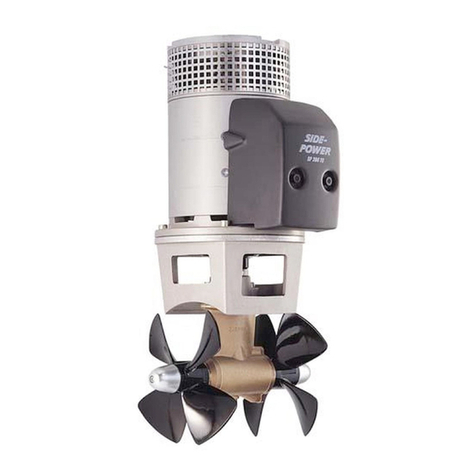
Volvo IPS650 User manual

IPS 2
IPS650, IPS800, IPS950
Installation
1(1)
E


Content
Safety Information ...................................................................................... 2
General Information .................................................................................... 5
Installation Tools and Documentation ...................................................... 8
Special Tools .......................................................................................... 10
System Information .................................................................................. 13
EVC .......................................................................................................... 13
Engine Characteristics ............................................................................. 14
Engine Application Ratings .................................................................. 14
Engine Performance .............................................................................. 15
Arrangement and Planning ...................................................................... 17
Engine Placement .................................................................................. 17
Engine Room .......................................................................................... 19
Sound Absorption .................................................................................. 30
Electrochemical Corrosion ................................................................... 33
Installation ................................................................................................. 51
Volvo Penta IPS ...................................................................................... 51
Fiberglass Hull Constructions ............................................................ 51
Aluminium Hull Constructions ........................................................... 81
Engine Foundation ............................................................................... 82
Propulsion Unit Installation ................................................................ 87
Engine Installation ............................................................................... 92
Extension Shaft .................................................................................... 96
Exhaust System ................................................................................... 98
Cooling System .................................................................................. 100
Fuel System .......................................................................................... 111
General ................................................................................................ 111
Fuel Tanks .......................................................................................... 112
Piping .................................................................................................. 116
Fuel pressure ...................................................................................... 118
Lubrication System .............................................................................. 119
Electrical System ................................................................................. 120
Batteries .............................................................................................. 121
Alternator ............................................................................................ 130
Voltage Supply ................................................................................... 131
Connection ......................................................................................... 132
Fire Extinguishing System .................................................................. 140
Calibration and Settings ......................................................................... 142
IPS Calibration ...................................................................................... 142
Launching and Sea Trial ........................................................................ 148
Alphabetical index .................................................................................. 155
47704162 10-2014 © AB VOLVO PENTA 1

Safety Information
This installation manual contains information required
for the correct installation of your Volvo Penta prod-
uct. Check that you have the correct manual.
Carefully read the chapters Safety precautions
and General information in the manual before
servicing or running the engine.
The following types of special warning messages can
be found in this manual and on the engine:
WARNING!
Indicates a hazardous situation which, if not avoided,
could result in death or serious personal injury.
IMPORTANT!
Indicates a situation which, if not avoided, could result
in property damage.
NOTICE! Important information that facilitates the
work process or item.
Set out below is a list of risks that must always be
borne in mind and the safety precautions that must
always be taken.
Plan ahead so that there is always sufficient
space for safe installation and (future) disassembly.
Lay out the engine compartment (and other compart-
ments such as the battery compartment) so that all
service points are accessible. Make sure not to come
into contact with rotating components, hot surfaces or
sharp edges when checking and servicing the engine.
Make sure that all equipment (e.g. pump drives, com-
pressors) has protective covers.
Make sure the engine cannot be started while
work is in progress by not connecting the electrical
system or by switching off electrical power to the
engine at the main switches and locking them in the
OFF position. Erect a warning sign at the helm station.
Only start the engine in well-ventilated areas.
Remember that exhaust fumes are toxic and danger-
ous to inhale. Use an exhaust extractor to lead
exhaust fumes away from the exhaust pipe and crank-
case ventilator when the engine is run in a confined
space.
Always wear protective goggles if there is a risk
of splinters, sparks and splashes from acid or other
chemicals. Eyes are extremely sensitive and injury
may result in loss of sight!
Avoid getting oil on the skin! Prolonged or
repeated contact with oil may lead to the disappear-
ance of the skin's natural oils. This will cause irritation,
dry skin, eczema and other skin problems. Old oil is
more hazardous to health than new. Use protective
gloves and avoid oil-soaked clothes and rags. wash
regularly, especially before meals. Use special skin
creams that facilitate cleaning and prevent the skin
from drying out.
Most chemical used in the product (engine and
reverse gear oil, glycol, gasoline and diesel) or chem-
icals intended for use in the workshop (degreasing
agents, paints and solvents) are health hazards. Read
the instructions on the product packaging carefully!
Always follow safety instructions (the use of protective
masks, protective goggles, gloves etc.). Make sure
that other personnel are not inadvertently exposed to
hazardous substances, e.g. in the air they breathe.
Ensure good ventilation. Hand in used and surplus
chemicals to a recycling station.
Take extreme care when searching for fuel sys-
tem leaks and testing injectors. Wear protective gog-
gles. The spray from an injector is at very high pres-
sure and fuel can force its way into tissue and cause
a serious risk of blood poisoning (septicemia).
Stop the engine and disconnect the power at the
main switches before working on the electrical sys-
tem.
2 47704162 10-2014 © AB VOLVO PENTA

Coupling adjustments must be made with the
engine stopped.
Use the lifting eyes installed on the engine/
reverse gear when lifting off the drive. Always check
that the lifting equipment is in good condition and has
the capacity to lift the engine (engine weight including
reverse gear and any auxiliary equipment installed).
If the engine has auxiliary equipment that has
altered its center of gravity, special lifting devices may
be required to obtain the correct balance for safe han-
dling.
Never work on an engine that is suspended in an
engine hoist.
It is mandatory that no work be carried out on a
running engine. There are however adjustments that
require the engine to be run. Approaching a running
engine is a safety risk. Loose clothes and long hair
can catch in rotating parts and cause serious injury. A
careless movement or a dropped tool may result in
injury when working in the vicinity of a running engine.
Be careful to avoid hot surfaces (exhaust pipes, tur-
bochargers, charge air manifolds, start elements etc.)
and hot liquids in pipes and hoses on engines that are
running or recently stopped. Re-install all protective
covers that were removed during maintenance work
before starting the engine.
Make sure that all warning and information decals
on the product are always visible. Change decals that
are damaged or painted over
Turbocharged engines: never start the engine
without the air cleaner installed. The rotating com-
pressor turbine in the turbocharger can cause severe
injury. Foreign objects that enter the inlet ducts can
also cause mechanical damage.
Never use start spray in the air intake. The use
of such products may result in an explosion in the inlet
manifold. Risk of injury.
Do not open the engine coolant filler cap (fresh-
water cooled engines) when the engine is hot. Steam
or hot coolant may be ejected when system pressure
is released. Open the filler cap slowly and release the
system pressure carefully (freshwater cooled
engines). Hot coolant may spray out if the filler cap or
drain tap is opened, or if a plug or coolant pipe is
removed from a hot engine.
Hot oil can cause burns. Avoid getting oil on the
skin. Be sure to release the pressure from the lubri-
cation system before starting work on it. Never start
or run an engine without the oil filler cap attached.
There is a risk of oil being ejected.
If the boat is in the water – stop the engine and
close the seawater tap before working on the system.
All fuels, and many chemicals, are flammable.
Make sure they are not exposed to open flames or
sparks. Gasoline, certain solvents and hydrogen from
batteries are extremely flammable and explosive in
the right concentration in air. No Smoking! Make sure
the workplace is well ventilated and take the neces-
sary safety precautions before welding or grinding in
the vicinity. Always have a fire extinguisher accessible
at the workplace.
Store oil, fuel-soaked rags and old fuel and oil
filters in the correct manner. Oil-soaked rags may
ignite spontaneously in certain conditions. Old fuel
and oil filters are harmful to the environment and must
be handed to a recycling station for destruction.
Make sure the battery compartment is built
according to current safety standards. Never allow
open flames or electrical sparks in the vicinity of the
batteries. Never smoke in the vicinity of the batteries.
Batteries give off hydrogen gas during charging,
which may combine with air to form an explosive mix-
ture. The gas mixture is extremely volatile and easily
ignited. Incorrect battery connection may cause
sparks which in turn may cause an explosion. Do not
change the battery connections when attempting to
start the engine (risk for sparks) and do not lean over
the batteries.
Safety Information
47704162 10-2014 © AB VOLVO PENTA 3

Make sure that the positive (+) and negative (–)
battery cables are correctly connected to the corre-
sponding battery terminals. Wrong connection may
cause severe damage to electrical equipment. Refer
to the wiring diagram.
Always wear protective goggles when charging
or handling batteries. Battery electrolyte contains
highly corrosive sulfuric acid. Wash immediately with
soap and copious amounts of water if battery electro-
lyte comes into contact with the skin. Flush immedi-
ately with water and seek medical attention if battery
acid gets in the eyes.
Never work alone when installing heavy compo-
nents, even when using safe lifting equipment e.g.
lockable blocks. Most lifting devices require the two
people, one to take care of the hoist and the other to
make sure no components catch or are damaged.
The components in the electrical system, ignition
system (gasoline engines) and fuel system on Volvo
Penta products are designed and manufactured to
minimize the risk of fire and explosion. Do not run
engines in areas where there are explosive materials.
Always use fuels recommended by Volvo Penta.
Refer to the Operator's Manual. Poor quality fuel may
damage the engine. Poor fuel quality in a diesel
engine may cause the fuel control mechanism to bind
which will lead to engine overspeeding with the risk of
engine damage and personal injury. Low fuel quality
may also lead to higher service costs.
Use an adjustable lifting beam to provide a safe
lift and to avoid damage to components on the top of
the engine. All chains and cables must run parallel
and be as square as possible to the top of the engine.
Safety Information
4 47704162 10-2014 © AB VOLVO PENTA

General Information
About this installation manual
This publication is intended as an installation guide for
Volvo Penta marine diesel engines for IPS installa-
tions. The publication is not exhaustive and does not
cover all conceivable installations, but should be con-
sidered as a recommendation and guidance accord-
ing to Volvo Penta norms. Detailed installation instruc-
tions accompany most accessory kits.
The recommendations are the result of many years of
practical experience from all over the world. If it is
necessary or desirable to depart from recommended
routines, Volvo Penta is happy to offer assistance in
finding a solution for the installation in question.
It is the responsibility of the installer to ensure that
installation is carried out in a satisfactory manner, that
the installation is in good operable condition, that
approved materials and accessories are used and
that the installation fulfills all current instructions and
regulations.
This installation manual is intended to be used by pro-
fessionally qualified and skilled personnel. It is there-
fore assumed that those persons using the manual
have fundamental knowledge of marine propulsion
systems and are capable of carrying out the associ-
ated mechanical and electrical work.
Volvo Penta continually improves it products and
reserves the right to make changes. All the informa-
tion in this manual is based on product specifications
available at the time of publication. After this date all
important product modifications that change installa-
tion methods will be communicated via service bulle-
tins.
Removal of complete engine assembly
In the event of a requirement to remove the entire
engine assembly from the vessel, it is the responsi-
bility of the boat builder to arrange reasonable means
for removal and re-installation.
Reasonable means that the engine assembly can be
lifted in and out within a moderate amount of time
using normal resources and methods available to the
industry. In this way costs and operational down-time
are kept to a minimum. For the sake of high demands
at high season on yards, the vessel manufacturers
instruction should be followed.
It is Volvo Penta policy to avoid unreasonable instal-
lations that increase extra costs for boat owners dur-
ing the lifetime of the boat.
Plan the installation carefully
Great care must be taken when installing engines and
their components if they are to function perfectly.
Make sure that the correct specifications, drawings
and other data are available before work is begun.
This facilitates correct planning and installation right
from the start.
Plan the engine compartment so that it will be easy to
perform routine service that involves changing com-
ponents. Compare the engine service manual to the
original drawings where dimensions are stated.
When installing engines, it is extremely important that
no dirt or foreign objects enter the fuel, cooling, inlet
or turbo systems, as this may cause faults or the
engine to seize. Because of this, systems must be
sealed. Clean supply lines and hoses before they are
connected to the engine. Remove the protective caps
from the engine when an external system is con-
nected.
General Information
47704162 10-2014 © AB VOLVO PENTA 5

Certified engines
A certified engine means that the engine manufac-
turer guarantees that both new engines and those in
operation fulfill legislation and regulations. The engine
must correspond to the unit used for certification. In
order for Volvo Penta to be able to declare that
engines fulfill environmental legislation, the following
must be observed during installation:
• Service on injection pumps, pump settings and
injectors must always be carried out by an
authorized Volvo Penta workshop.
• The engine may not be modified in any way
except with accessories and service kits devel-
oped for the purpose by Volvo Penta.
• The installation of exhaust pipes and air intakes
(ventilation ducts) in the engine compartment
must be carefully planned as their design may
influence exhaust emissions.
• Seals may only be broken by authorized per-
sonnel.
IMPORTANT!
Only use genuine Volvo Penta parts. If non-Volvo
Penta parts are used it will mean that Volvo Penta
is no longer able to take responsibility for the
engine fulfilling certification requirements. Volvo
Penta will not reimburse damages and costs arising
from the use of non-Volvo Penta spare parts.
Seaworthiness
It is the responsibility of the boat builder to meet all
safety requirements applicable in the market where
the boat is sold. For example, in the U.S.A. US Fed-
eral Regulations for pleasure boats specify require-
ments. Requirements applicable in the EU are descri-
bed below. In other markets, contact the competent
national authority for information and detailed descrip-
tions of safety requirements.
From June 16 1998, all leisure craft and certain asso-
ciated equipment that is marketed and used within the
EU must be provided with a CE label confirming ful-
fillment of safety requirements established by the
European Parliament and European commission in
the Recreational Craft Directive. These normative
standards are reflected in the standards established
in support of the directive's objective regarding uni-
form safety requirements for leisure craft within the
EU.
Lifeboats and boats used in commercial navigation
are approved by classification societies in the country
where the boat is registered.
Mutual responsibility
Every engine consists of a large number of compo-
nents working in unison. If one component deviates
from technical specifications it may lead to the engine
having a significantly greater impact on the environ-
ment. It is therefore essential that adjustable systems
are set correctly and that genuine Volvo Penta parts
are used.
Certain systems (e.g. the fuel system) may require
special professional expertise and test equipment.
For environmental reasons, some components are
factory sealed. No work may be performed on sealed
parts by unauthorized personnel.
Remember that most chemical products can harm the
environment if they are used in the wrong manner.
Volvo Penta recommends the use of bio-degradable
de-greasing agents for cleaning engine components,
unless the service manual states otherwise. When
working onboard take especial care to ensure that oil
and spills are collected for handing to a re-cycling sta-
tion and not unintentionally pumped into the environ-
ment with bilgewater.
General Information
6 47704162 10-2014 © AB VOLVO PENTA

Metric Conversion Chart
Metric to American or UK units: American or UK to metric units:
To convert Multiply To convert Multiply
From To with From To with
Length mm in. 0.03937 in. mm 25.40
cm in. 0.3937 in. cm 2.540
m ft. 3.2808 ft. m 0.3048
Area mm² sq. in. 0.00155 sq. in. mm² 645.3
m² sq.ft. 10.76 sq. ft. m² 0.093
Volume cm³ cu. in. 0.06102 cu. in. cm³ 16.388
l, dm³ cu. ft. 0.03531 cu. ft. l, dm³ 28.317
l, dm³ cu. in. 61.023 cu. in. l, dm³ 0.01639
l, dm³ imp. gallon 0.220 imp. gallon l, dm³ 4.545
l, dm³ U.S. gallon 0.2642 U.S. gallon l, dm³ 3.785
m³ cu. ft. 35.315 cu. ft. cm³ 0.0283
Power N lbf 0.2248 lbf N 4.448
Weight kg kg lb. 2.205 lb. kg 0.454
Output kW hp (metric)(1) 1.36 hp (metric)(1) kW 0.735
kW bhp 1.341 bhp kW 0.7457
kW BTU/min 56.87 BTU/min kW 0.0176
Tightening
torques
Nm lbf ft 0.738 lbf ft Nm 1.356
Pressures Bar psi 14.5038 psi Bar 0.06895
MPa psi 145.038 psi MPa 0.006895
Pa mm Wg 0.102 mm Wg Pa 9.807
Pa in Wg 0.004 in Wg Pa 249.098
kPa in Wg 4.0 in Wg kPa 0.24908
mWg in Wg 39.37 in Wg mWg 0.0254
Energy kJ/kWh BTU/hph 0.697 BTU/hph kJ/kWh 1.435
Labor kJ/kg BTU/lb 0.430 BTU/lb kJ/kg 2.326
MJ/kg BTU/lb 430 BTU/lb MJ/kg 0.00233
kJ/kg kcal/kg 0.239 kcal/kg kJ/kg 4.184
Fuel cons. g/kWh g/hph 0.736 g/hph g/kWh 1.36
g/kWh lb/hph 0.00162 lb/hph g/kWh 616.78
Moment of
inertia
kgm² lbft² 23.734 lbft² kgm² 0.042
Flow, gas m³/h cu.ft./min. 0.5886 cu.ft./min. m³/h 1.699
Flow, fluids m³/h US gal/min 4.403 US gal/min m³/h 0.2271
Speed m/s ft./s 3.281 ft./s m/s 0.3048
mph knots 0.869 knots mph 1.1508
Temperature Celsius Fahrenheit °F=9/5 x °C
+32
Fahrenheit Celsius °C=5/9 x (°F–
32)
1) All catalog output data specified in horsepower refers to metric horsepower.
General Information
47704162 10-2014 © AB VOLVO PENTA 7

Installation Tools and Documentation
Publications
Installation manuals
Manuals are available for the EVC system, for exam-
ple.
Installation instructions
There are installation instructions included with most
kits.
Drawings
Drawings are included in kits and additional drawings
are available electronically from Volvo Penta.
B E
Installation
P0014255
Installation Tools and Documentation
8 47704162 10-2014 © AB VOLVO PENTA

Posters
Refer to posters for the design of hull inserts, lamina-
tions, drive unit installation and the installation and cal-
ibration of the EVC system.
VODIA
The VODIA diagnostic tool is used for reading fault
codes in clear text during diagnosis work. It can also
be used for setting EVC parameters.
The tool is very practical for fault tracing as it is possible
to see the values the EVC nodes are reading and
sending.
Refer to VODIA information at Volvo Penta Partner
Network or contact Volvo Penta to order.
Chemicals
There is a large range of chemicals available from
Volvo Penta.
Some examples:
•Oil and coolant
•Sealing compound and grease
•Touch-up paint
Refer to Volvo Penta Spare Parts & accessories.
EVC-C3
P00008985
VODIA
p0006256
A
n
tifo
u
l
i
n
g
P0004585
Installation Tools and Documentation
47704162 10-2014 © AB VOLVO PENTA 9

Special Tools
P0010517
P0010518
P0010505
3849633 Drill jig 3594503 Drill jig 21110860 Lifting tool
Location of engine bed and
engine mount positions (hull
inserts)
Lamination of hull inserts and
the location of engine beds
(complete with molding tools).
Attaching device for propulsion
unit when lifting by hoist
P0010506
p0010872
3849664 Lifting tool 3887101 Break-out box 21406897 Calibration tool
Position device when lifting by
fork lift
Used together with the VODIA
tool for calibrating IPS units
Drive unit alignment (complete
pair)
P0001856
3863070 Allen key socket
Torque tightening propeller
retainer rings
Installation Tools and Documentation, Special Tools
10 47704162 10-2014 © AB VOLVO PENTA

Other Special Equipment
p0005125
VODIAVODIA
p0008375
P0004580
88890074 Multimeter 88820047 VODIA, diagnostic
tool
9998493 Hose
Used in combination with
9998339 Manometer.
PDA only
P0008329
P0004349
21244540 Measuring tool 9998339 Manometer
Measuring engine mount com-
pression
Measuring fuel feed pressure
Installation Tools and Documentation, Special Tools
47704162 10-2014 © AB VOLVO PENTA 11

Chemical products
P0001874
P0001871
828250 Grease alt.
21347121 Grease (400 gr)
1381065 Corrosion protec-
tion
3817243 Rubber lubricant
Installation Tools and Documentation, Special Tools
12 47704162 10-2014 © AB VOLVO PENTA

System Information
EVC
Refer to the Installation EVC installation manual for
EVC system installation instructions.
System Information, EVC
47704162 10-2014 © AB VOLVO PENTA 13

Engine Characteristics
Engine Application Ratings
The engines covered by this manual are used chiefly
in two different operating conditions: Rating 4 and Rat-
ing 5, as described below.
Rating 4
Special light commercial traffic
For light, planing boats in commercial traffic. Operated
for fewer than 800 hours per year.
Typical boats: High-speed patrol boats for search and
rescue and the armed forces, and special high-speed
fishing boats. Recommended cruising speed: 25
knots.
Full power may be utilized for max 1 hour per 12 hour
period. Between full-throttle periods, engine revolu-
tions must be reduced by at least 10% from full rpm.
Rating 5
Recreational use
Only for pleasure boats operated by owners for their
recreation. Operated for fewer than 300 hours per
year.
Full power may be utilized for max 1 hour per 12 hour
period.
Between full-throttle periods, engine revolutions must
be reduced by at least 10% from full rpm.
Engine Characteristics, Engine Application Ratings
14 47704162 10-2014 © AB VOLVO PENTA

Engine Performance
Marine engine power is specified, just like automobile
and truck engines, according to one or more power
norms. Power is specified in kW or hp, always at a
rated rpm.
Most engines provide the power specified on the con-
dition that they have been tested in the conditions the
power norms state, and have been broken in properly.
According to ISO standards, tolerances are normally
±5 %, which is a reality that must be accepted for ser-
ies-produced engines.
Power measurement
Engine manufacturers normally measure engine
power at the flywheel, but before power reaches the
propeller, losses occur in the drive train and propeller
shaft bearings. These losses amount to 4–6 %.
All major marine engine manufacturers determine
engine power according to ISO 8665 (supplement to
ISO 3046 for pleasure boats). If an exhaust system is
not included, engine tests are performed with a back
pressure of 10 kPa (1.45 psi).
Engine performance
Engine power is affected by a number of different fac-
tors. Among the most important are air pressure, out-
door temperature, humidity, fuel calorific value and
exhaust back pressure. Deviations from normal values
affect diesel and gasoline engines in different ways.
Diesel engines use large amounts of air for combus-
tion. If the mass of air is reduced, the first sign is an
increase in black exhaust smoke. The effects of this
are especially noticeable at the planing threshold when
the engine must produce maximum torque.
If the deviation differs significantly from normal air flow,
the diesel engine will lose power. In the worst case the
loss may be so great that torque is insufficient for the
boat to overcome the planing threshold.
Point A is where the indicated engine power is equal
to the power acting on the propeller. Volvo Penta IPS
drive units have defined propeller sizes that are dimen-
sioned for engine characteristics.
1
2
3
4
56
A
B
C
P0004571
Connection between performance-influencing factors in inboard
engines
1Power
2 rpm
3 Power loss due to atmospheric conditions
4 Loss due to large propeller
5 Critical area
6 Indicated rpm
Engine Characteristics, Engine Performance
47704162 10-2014 © AB VOLVO PENTA 15

Other factors that influence performance
It is important to keep exhaust back pressure low.
Power losses caused by back pressure are directly
proportional to the increase in back pressure, which
also increases exhaust temperature.
Boat weight is another important factor that influences
speed. Increased boat weight has a great influence on
speed, especially on planing or semi-planing hulls. A
new boat that is tested with half full fuel and water tanks
and without a load, may lose 2-3 knots when it is driven
fully loaded with fuel, water and equipment for the voy-
age.
Boats made from fiberglass reinforced plastic absorb
water when they are afloat which means they become
heavier over time. Marine fouling is an often-over-
looked problem that greatly affects boat performance.
Engine Characteristics, Engine Performance
16 47704162 10-2014 © AB VOLVO PENTA

Arrangement and Planning
Engine Placement
Engine Inclination
To ensure the engine receives lubrication and cooling
in a satisfactory manner, it is important that maximum
engine inclination is not exceeded. Engine inclination
must therefore be checked.
Be careful to avoid the front of the engine's being lower
than the flywheel, i.e. an exaggerated negative incli-
nation that may impair engine lubrication and cooling
system venting.
Each engine type has a maximum permissible engine
inclination while the boat is under way. This inclination
includes both the installation angle and the increase in
trim angle the boat attains when moving at speed
through the water.
A Engine inclination with the boat at rest.
B Boat trim angle under way.
C Total engine inclination under way, maximum per-
missible inclination (A+B).
A boat's weight distribution is affected by the choice of
driveshaft length.
See technical data for limit values.
P0010566
A
B
C
Arrangement and Planning, Engine Placement
47704162 10-2014 © AB VOLVO PENTA 17

Weight Distribution
The location of the longitudinal center of gravity is of
great importance for trim angle at top speed etc. Gen-
erally speaking, a fast boat should have its center of
gravity further aft than a slower boat.
The center of gravity has great influence on a boat's
static and dynamic stability. It is therefore important to
consider CoG position both when the boat is loaded
and unloaded.
It is important that heavy components such as engines,
fuel and water tanks and batteries be located such that
the best possible trim is achieved when the boat is in
the water, and generally that as low a vertical CoG as
possible is attained.
Fuel and water tanks must be located longitudinally as
close to the center of gravity as possible in order that
the center of gravity is not moved when water and fuel
levels change.
It is an advantage not to locate the fuel tanks in the
vicinity of the hot engine compartment. If possible, the
batteries must be located in a separate, well-ventilated
section.
Clearance Around Propulsion Units
Objects that protrude from the hull bottom cause tur-
bulence. If such are present in the vicinity of the drive
units, propeller propulsion ability will be impaired.
Place no objects inside the dashed lines.
Amin. 3000 mm (118")
Bmin. 400 mm (16")
Cmin. 50 mm (2")
Clearance between hull and Ips drive unit is 9 mm
(+ 5 mm - 2 mm)
A
B
P0005314
Figure A shows an installation with good weight distribution and trim
angle.
Figure B shows an incorrect installation with poor trim angle as the
result.
A
B
B
P0006153
P0019672
C
Arrangement and Planning, Engine Placement
18 47704162 10-2014 © AB VOLVO PENTA
This manual suits for next models
2
Table of contents