Wendt X3 User manual

Front Panel
1. Fader Controls — The faders are marked CHANNEL 1, 2 and 3 which correspond to the mic XLR inputs also marked
CHANNEL 1, 2 and 3. These channel faders control the post preamp gain.
2. VU Meters (LED) — The VU meters are LED displays where the 0db LED position is 0db VU and the numbers correspond
to decibel units. The left display is located above Channel 1 fader and the right display is located above Channel 3 fader.
3. Low Cut Filters — The switches marked 140 20 100 insert a 12db per octave hi pass filter in each channel as follows:
the 20 position is a flat response to 20HZ, and the 100 and 140 positions roll off at 100 HZ and 140HZ.
4. Pan Switches — The switches marked L PAN R allow assignment of the individual channels to the left and right mixing
busses. The center position assigns each channel to the right and left mixing busses.
5. Reference Tone — The TONE button when pushed IN (push on/push off switch) enables a 400HZ reference tone oscillator
which provides a 0db VU reference tone to the right and left line outputs. The push button OUT position disables the tone.
6. Slate Mic — The push button switch marked SLATE when pushed in, enables the slate function which is outputted to the
left and right LINE, AUX and LINK outputs.
7. Power Monitor — The LED marked PWR MON slowly cycles on and off under normal power voltage conditions and
turns to a continuous ON when external power or battery voltages are low. Typically when the LED changes to a continuous
ON condition, the time remaining for battery use is 1/2 to 1 hour.
8. Battery Test — The push button switch marked BATT TEST tests the battery or external power source voltage which is
indicated on the right LED VU display. A set of new alkaline batteries will indicate up to and including the 0db position on the
display.
9. Power Switch — The three position POWER switch marked INT OFF EXT allows the mixer to be powered from the
internal (batteries) or an external power source. The center switch position is OFF (no power source is connected).
10. Return-Mix — This switch allows the monitor output (headphones) to receive audio from an external source (RTN) or
internal (mixer).
rev. 6/05
Wendt Inc., Westlake Village, CA, USA
Tel: 805 494-4432
E-mail: [email protected]
www.wendtaudio.com
®
Wendt X3 Operating Instructions
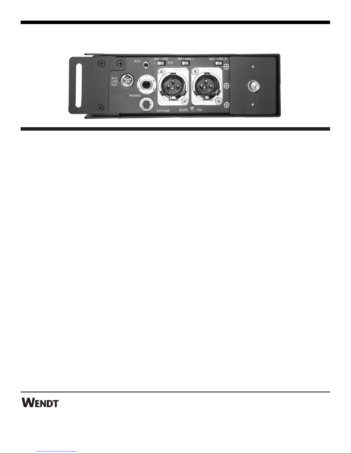
Right Side Panel
1. Slate Volume — The trim pot marked SLATE VOL is a screwdriver slate mic gain control adjustment.
2. Mic-Line Outputs — The right and left line outputs provide electronically balanced line or mic levels. Each output can
be switched from line level to mic level using the MIC-LINE switch. In the LINE position full drive capability is available
and in the MIC position the line level is attenuated by 50db. These outputs are XLR connectors which are wired pin 1 - ground,
pin 2 - hi, and pin 3 - low.
3. External Power — A quick release 4 pin Hirose connector marked EXT PWR allows the unit to operate from an external
power source of 9V-18V. The mating connector is a Hirose, HR10A-7P-4P, which must be wired such that pin 4 is positive
voltage and pin 1 is negative voltage.
4. Stereo Returns — The mini jack (3.5mm) marked RTN is a stereo return from any remote location desired. This return is
unbalanced where the connector ring is ground, the tip is left and the second ring is right.
5. Aux-Link — The 5 pin TA connector has the following output functions:
A. Link Output — The LINK Output which connects the X3 to the Wendt X5 is available via the 5 pin TA
connector where pin 1 is RT and pin 3 is LT. This output is -15db relative to LINE, 3K ohms output impedance, and
phase 180 degrees relative to LINE. Pins 1 and 3 can be used as stereo out, mono out (jumper pin 1 and 3 in mating
connector) or LINK to Wendt X5 mixer via the X5 standard link or other cable. When using the standard X5 link
cable it is recommended that the AUX switch be set in the MIC position.
B. Aux — The AUX stereo output is unbalanced and is available on the 5 pin TA connector where pin 2 is RT and
pin 4 is LT. These outputs are in phase with LINE and can be switched to MIC (-50db relative to Line) or LINE (-3db
relative to Line) via the AUX switch. In the MIC mode the output impedance is approximately 150 ohms and in the
LINE mode the output impedance is approximately 3K ohms. These outputs can be used in a stereo mode or in a
mono mode (jumper pin 2 and 4 in mating connector).
The mating connector for the 5 pin output is Switchcraft TA5F.
6. AUX switch — See paragraph 5-B.
rev. 6/05
Wendt Inc., Westlake Village, CA, USA
Tel: 805 494-4432
E-mail: [email protected]
www.wendtaudio.com
®
Wendt X3 Operating Instructions
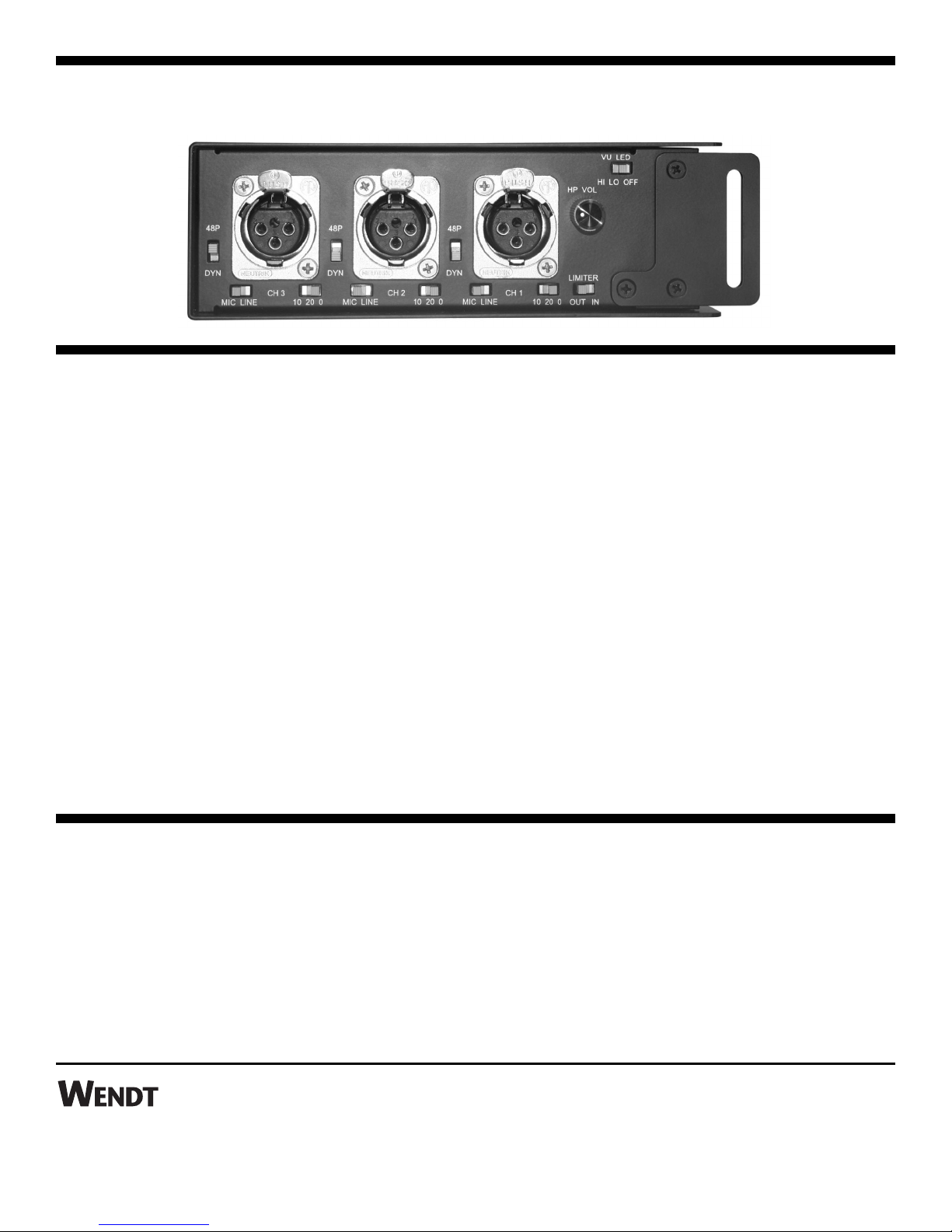
Left Side Panel
1. Mic-Line Inputs, Channel 1, 2 and 3 — The XLR mic or line inputs are electronically balanced where pin 1 is ground,
pin 2 is input high, and pin 3 is input low. Either pin 2 or 3 may be tied to ground. The switches labeled MIC-LINE switch
in a -50db attenuator for LINE and direct pre-amp for MIC.
2. Mic Powering — The mic powering switch labeled 48P and DYN allows two modes of mic powering. 48V for phantom
powered mics, and the dynamic (DYN) position which is non-powered for dynamic mics or wireless receivers.
3. Preamplifier Gain — The switch labeled 10 20 0 controls the preamplifier gain where “0” is maximum gain, 10 reduces
the gain by 10db, and 20 reduces the gain by 20db. The 10 and 20 positions are typically used for powered mics.
4. HP Volume — The knob marked HP VOL controls the phone volume.
5. VU LED — The three position switch marked VU LED controls the brightness of the VU display. HI (maximum brightness),
LO (minimum brightness), and OFF (VU display off). The display remains active in the OFF position during battery test.
6. Limiter — The stereo limiting function is controlled by the switch marked LIMITER (OUT IN) where the limiting function
is enabled in the IN position. This limiter compresses post fader gain.
rev. 6/05
Wendt Inc., Westlake Village, CA, USA
Tel: 805 494-4432
E-mail: [email protected]
www.wendtaudio.com
®
LIMITED WARRANTY
Wendt Inc. products are covered by a one year warranty to be free from defects in material and workmanship. In the event
your Wendt Inc. product needs repair please call us for a return authorization and then carefully pack and ship it to us pre-
paid. We will repair or replace at our option and return ship via carrier and method of Wendt Inc.’s choice. This warranty does
not apply to defects caused by misuse, abuse or altered goods. There are no express or implied warranties which extend beyond
the warranty made here.
Wendt X3 Operating Instructions
Table of contents


