5.2 First Time Operation
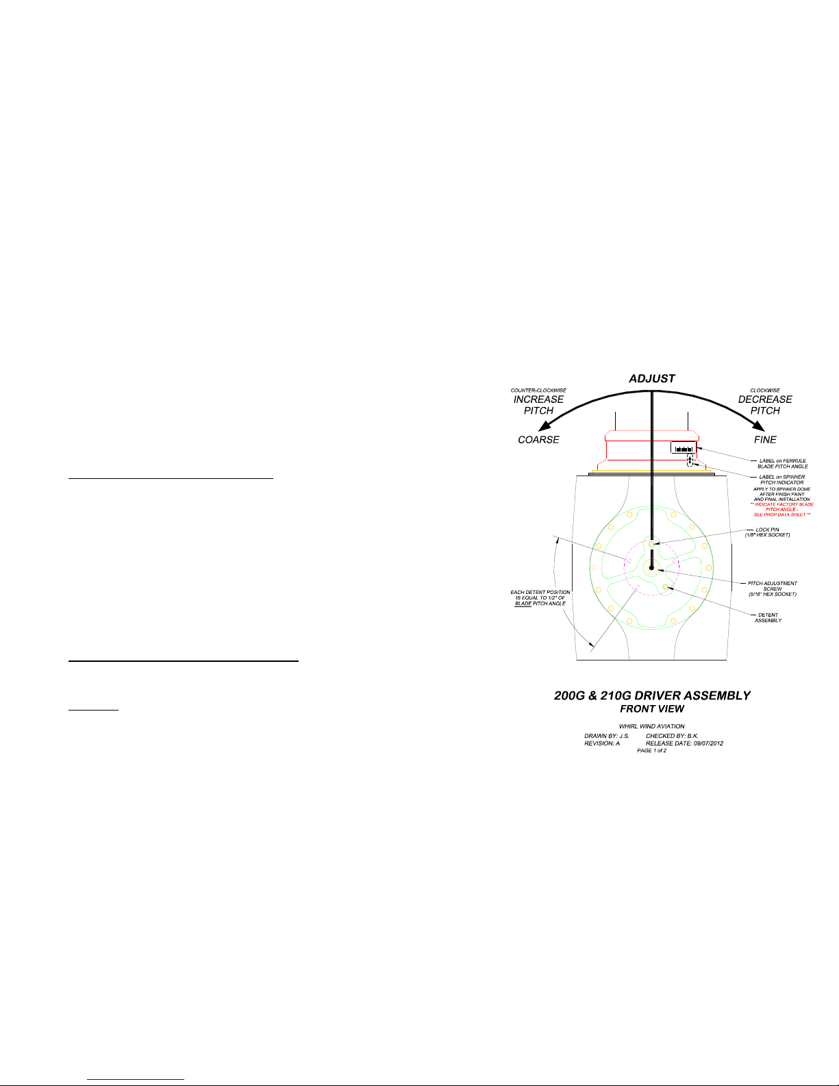
Do not change the pitch adjustment screw until the
propeller is installed on the airplane and the pitch scale
and indicator are installed on the blade ferrule and the
spinner dome (see Figures 5-2 and 5-3 below).
Per Figure 5-2, place the pitch indicator arrow label on the
spinner dome indicating the factory low pitch setting.
* Refer to the original propeller data sheet for initial factory
low pitch setting.
5.3 First Run-Up
The primary objective of the first run-up series is to
establish baseline values for engine RPM at full power
(maximum throttle with various blade pitch angles.
CAUTION! As stated above, many airplane and propeller
manufacturers do not recommend high power run-ups due to
the possibility of debris damage. If a high engine speeds are
required be sure to perform the run up on a clean surface
and you are in a safe, unobstructed area.
Follow your airplane’s manual and perform an engine run-up
using the factory set low pitch setting.
The RPM restrictions from the engine and propeller
manufacturers must be strictly observed.
The initial factory set low pitch setting (refer to original
propeller data sheet) may be too fine for your engine and
could lead to an engine over speed. Advance the throttle
slowly to be sure that an over speed does not occur!
If the engine can not reach 2,250 to 2,300 RPM at full
throttle the factory setting is too coarse. DECREASE the
blade pitch angle by ½° increments following the propeller
pitch changing instructions below. For each ½° decrease of
blade pitch angle repeat the run up to full throttle until the
correct pitch setting is found that maintains 2,250 to 2,300
RPM at full power.
5-3
If the engine wants to exceed 2,250 to 2,300 RPM at full
throttle the factory setting is too fine. INCREASE the blade pitch
angle by ½° increments following the propeller pitch changing
instructions below. For each ½° increase of blade pitch angle
repeat the run up to full throttle until the correct pitch setting is
found that maintains 2,250 to 2,300 RPM at full power.
Note: The procedure above is recommended to establish
baseline settings of blade pitch and resultant engine speeds
(RPM) at full power. 2,250 RPM is only an example – a
conservative RPM for safety and prevention of engine over
speed. The most appropriate baseline settings will vary for each
application. As this procedure is completed record the static
RPM in the table on page 5-2 for future reference.
5.4 Inspection After First Run-Up
1. Inspect the propeller system blades and spinner for any
nicks, cracks, or chips.
2. Inspect each aluminum blade ferrule and blade intersection
(located at the root end of blade where the silicone sealant is
visible) for movement and/or signs of chafing. There should
be no movement between the aluminum ferrule and the
blade. Notify Whirl Wind Aviation immediately if movement
is detected.
3. Gently shake each propeller blade to feel for blade
movement in the hub. Blade shake movement is allowed up
to 1/8 inch measured from the tip. Radial play of up to 2
degrees is acceptable. If the check shows values above
these tolerances contact Whirl Wind Aviation immediately.
Movement is only allowed between the aluminum blade
ferrule and the propeller hub – and not as described in point
#2 above.
4. Inspect the nickel leading edge erosion shield. The nickel
erosion shield should not be loose or have any cracks. Small
paint cracks parallel to and along the edge of the shield
where the nickel and paint meet are acceptable.
5. Check the spinner dome and the aft and forward bulkheads
for cracks of any kind or looseness.
Your Whirl Wind Propeller System has been statically balanced
at the factory. However, it is recommended to have the
engine/propeller dynamically balanced before the first flight.
5-4