Whirlwind Mix 6 User manual

U.S. Audio
whirlwind OPERATIONS MANUAL
Mix 6
STEREO MIXER
UNPACKING
INTRODUCTION US Audio has made e\'erv effort to ensure that your equipment is received
Thank you for selecting the US Audio Mix 6. The Mix 6 delivers the ultimate in the same perfect condition it was in when it left the factory. Please
in sonic performance for the most demanding professional mic and line inspect your product for any signs of damage during shipping and report
mixing applications. Utilizing the Analog Devices 2017 IC, a carefully them to your dealer so that he can present a claim to the shipper. \Ve
wound toroidal power transformer, trUe star grounding, plus many other recommend that you save your packaging material for use in the unlikely
design features, the Mix 6 has a working signal to noise ratio (S/N) of 92db event that you need to return your equipment for service.
with22dBheadroomatunitygain!At40dBofgaintheMix6holdsaworking
S/N of 85dB making it ideally suited for production with digital recording
media. The Mix 6 can provide up to 76dB of gain, with a professional quality
signal to noise ratio and still have 10 to 15dB of headroom. Other features
include 2 stereo aux inputs, one of which can be used as a separate monitor
input,astereopeak limiter,lowcutfilters andaheadphonecircuit. \Vithafull
complement of hook-up hardware, the Mix 6 is capable of handling any
configuration of line or mic level signals as well as any combination of
balancedorunbalancedXLRand1/4”connectors.

THEORY OFOPERATION
The US Audio Mix 6 has four mic or line input channels and two stereo aux line inputs. All of the
XLRand1/4”inputandoutputjacks,exceptaux1,areactive electronically balanced circuits. The
Theoutputsection of the Mix 6 was designed to accommodate any configuration, line or miclevel
inputsectionsofchannels1-4on the Mix 6 use the relatively new Analog Devices 2017 integrated
balanced or unbalanced XLR and balanced or unbalanced 1/4” connectors. Each channel's output
circuit, which was designed to yield high amounts of gain with the lowest possible noise. This IC,
jacksareindividuallybufferedsoanycombination ofthe outputs,at anyimpedance, willnot affect
alongwith carefulcomponentselection, atoroidalpower transformer,andtrue stargroundingon a
theotheroutputs. WiththeMic/Lineoutputswitch intheMicposition,theXLR'soutput isreduced
2 ounce copper double sided circuit board, enable the Mix 6 to achieve a working signal to noise
by 20db (this switch does not affect the 1/4” jacks). The Mix 6 uses an H-Pad resistor network at
ratio (S/N) of 92db with 22dB of headroom at unity gain. The Mix 6 holds a working S/N ratio of
the XLR to maintain the S/N ratio, regardless of the position of the Mic/l.ine switch. For the XLR
85dbat 40db ofgainandcan provide upto76dBof gain, stillmaintaining10to 15db ofheadroom.
outputs,ifgroundliftingofpin 1isdesired,jumpersJMP6andJMP7insidetheunitcan beclipped
Withthe mic/line switch is in the micposition,the2017is factory set at 36db of gainbyaninternal
off. Then, in Line mode pin 1 of the XLR is completely lifted and in Mic mode the XLR's pin 1 is
resistor. This 36db plus the two sections of 20 dB available from each of the channel volumes and
ground isolated and referenced to pins 2 and 3. If unbalanced operation is desired from the XLR
mastervolumeofferatotalgainof76db.Forapplicationswhichneedevenmore,theMix6canbe
outputs,pin2ishot,pin1isground, andpin3 shouldbeleftUNCONNECTED.
orderedormodifiedtoobtainupto50dBof gainfromthe 2017viaasimpleresistorchange.
LEDdBmeters provided on the Mix 6 are precisely calibrated at 3dB incrementsandspanarange
Allthe gain controls on the Mix6 (Channel gain, Aux and Master)have a range of -60 to+20dbm.
of -15 to +l2dBm measured unbalanced at the 1/4” output. The output of the XLR, with the switch
With the input and output switches in the Line position and with both the channel and master
inLinemode,is6dbgreater,measuredbalanced.
volume controls at the same position, unity gain is at the 9 O'clock knob position, 10dB gain at 12
O'clock,and 15dBgainat 3O'clock.The 60dbof attenuation inthe off positionallows the Mix6 to
adequately turn off line level signals. Maximum signal level through the Mix 6 at clipping is
The limiter section of the Mix 6 is pre master fader, allowing versatility in selection of output
+28dBm balanced and +22dBm unbalanced. The sonic figures apply to both the input and the
levels while the peak limiter is active. The limiter is true stereo, with separate detectors for each
outputandindividualclipLEDsareprovidedwhichilluminateat-3dBbelowactualclipping.The
side, which engage at 0dB and limit up to 15dB. The left and right LEDs on the front panel
OL(Over Load) circuit sensesthesignal level in 2places(input diff amp andafterchannelgain) to
illuminate when the limiter is working and get brighter as limiting increases. With a quick attack
ensurefoolproofvisualindicationofdistortion.
timeandmoderateratiothelimiterisidealforopenmicsituationswhereunexpected levelchanges
canoccur.
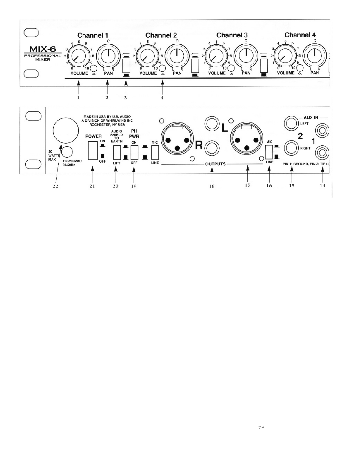
Channels 1-4 have a pan control. The center detented, dual element, audio taper pot provides a
wide range of stereo positioning for the input signal. The center detent allows quick centering of
The Mix 6 has a headphone monitoring section consisting of a source select switch, a volume
the signal. Also included on channels 1-4 is a low frequency rolloff switch for elimination of sub
control, and a 1/4” TRS headphone jack. The headphone circuit is stereo and drives any
frequencies such as mic handling or wind noise. The cutoff frequency is 120Hz with a 24dB per
headphones with 20 Ohms or greater impedance. The volume control has a gain range of -60 to
octaveslope.
+20db to accommodate a wide range of audio levels. The select switch allows listening to either
theprefaderstereomasteroutputsorthepostfadersignal comingfromthe aux2inputs.
Aux inputs one and two are true stereo line level inputs. Aux input 1 is via unbalanced RCA jacks.
Aux input 2 is accessed through left and right balanced 1/4” TRS jacks, which can be used
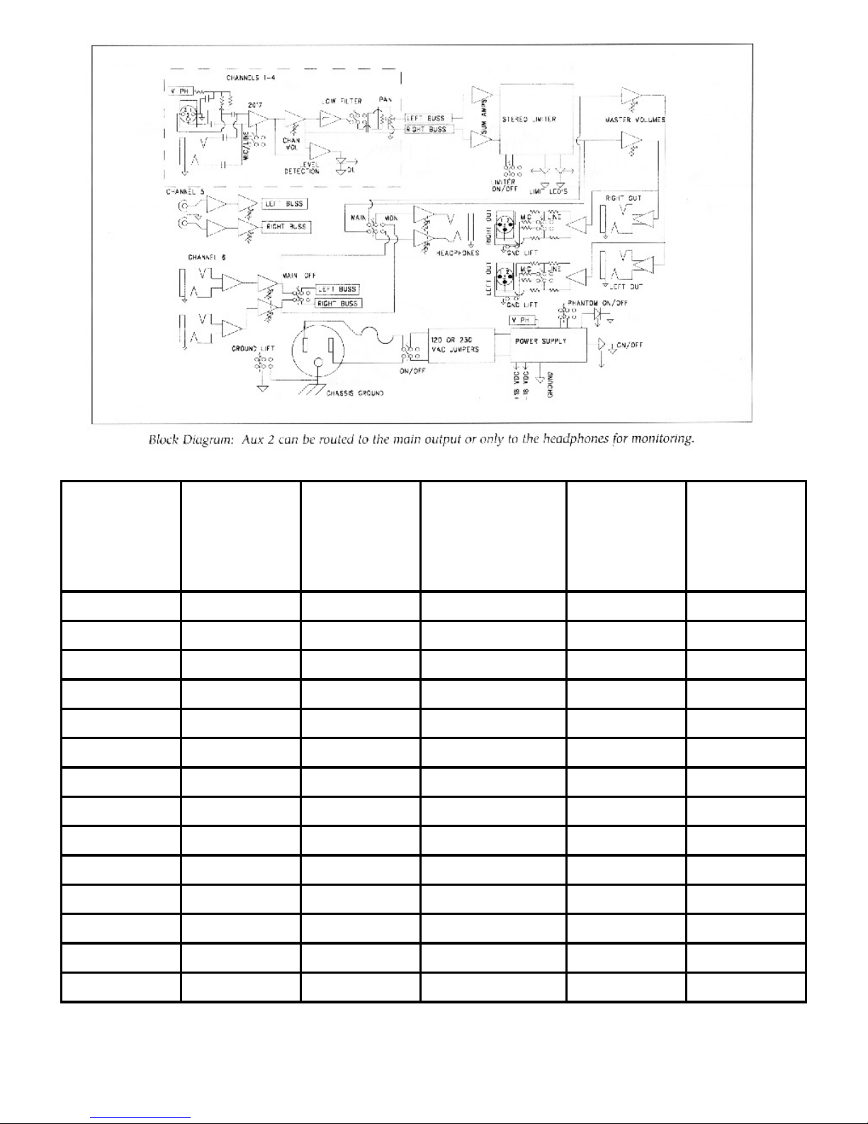
The Mix 6 utilizes a dual primary toroidal power transformer which is configured with internal
balanced or unbalanced. Aux 2 has a unique main/off switch which routes the input signal to the
jumpersfor 120 VAC60Hz or 230VAC 50Hz operation.Thereis aninternalfuse on thehotside of
left and right stereo busses when activated. This feature allows aux 2 to be disconnected from the
theACcord,andthepowerswitchmakesandbreaksboththehotandneutrallegsoftheACcord.A
mainoutputandin combinationwith theheadphone main/monswitch,routesthesignal toonly the
ground lift switch is provided which can disconnect the audio circuit ground from the AC chassis
headphones for cueing or monitoring. The Mix 6 aux inputs will interface easily with most all
ground.
typesofconsumerorprofessionalequipment.

the “in” position and lifts the signal when “out”. Signal to the headphone switch is
CONTROLS AND CONNECTIONS alwayson.
1. ChannelVolumePotscontrolinputsignalsoverarangeof 7. Master Volume Potsdetermine the amount of signal from the summing amps
thatis fed to the outputdrivers and themeters. These also have again range of-60 to
6OdBmattenuationatfulloffto2OdBmofgainatfullon. i-2OdBm.
2. PanPotsaredual potswith centerdetent, offeringover 65dBof stereoisolation 8. LEDdB Indicatorsare preciselycalibrated at3dB increments andspan arange
from left to right channel. The center detent allows convenient and accurate setup, of -15 to +l2dBm measured unbalanced at the 1/4” output. The output of the XLR,
feedingsignalequallytobothchannels. withtheswitchinLinemode,is6dBgreater.
3. Low frequency Cut Switch for reduction of wind noise, etc. The cutoff 9. StereoPeak Limiteris pre master fader and is switchable in or out of the signal
frequencyis120Hzwitha24dBslope. path. Threshold is set at 0dB and limiting up to 15dB is possible. The left and right
LEDs on the front panel illuminate when the limiter is working and get brighter as
limitingincreases.Attacktimeisfastandtheratioisapproximately4:1.
4. OL (Over Load) LEDilluminates when the level is 3dB below distortion. The
clipcircuitsensesthesignallevelattheinputdiffampandafterthechannelgain.
10. Stereo Headphone Circuit consists of a source select switch, a volume
control, a 1/4” TRS headphone jack and will drive any headphones with 20 ohms or
5. Aux1InputPot controlsthe rearpanel RCA jacks. Aux Iis astereo unbalanced greater impedance. The volume control has a gain range of -60 to +20db. The select
circuit feeding the left and right busses. This control has a gain range of -60 to -~- switch feeds either the prefader stereo master signal or the aux 2 postfader signal to
20dB. theheadphoneamplifier.
6. Aux 2 Input Pot controls the rear panel stereo 1/4” TRS balanced jacks through
a gain range of -60 to +20dB. Postfader signal is fed to the headphone select switch 11. LED Indicators for Phantom Power and Unit Power illuminate
“mon' position allowing aux 2 to become an external input to the headphone circuit. when rear panel switches are activated.
Themain/offswitch routes theaux2 inputsignalto theleftandright stereobussesin

12. Input 1/4 TRS and XLR Jacks are AC coupled through
phantom blocking capacitors with pin 2 being positive wired to tip,
pin 3 being negative wired to ring and pin 1 being common wired to 19. PhantomPower Switchactivates 48V DC on channel 1-4 XLR
sleeve. inputs. Status is indicated by the front panel LED. Each of the mic
inputs is filtered to eliminate crosstalk through the supply rail and
phantompowerisisolatedfromtheTRSjacks.
13. Input MidLine Switch is connected to an active circuit and
turnson 36dB ofgain when pushedin to the Mic position. This gainis
appliedtobothinputjacks. 20. Ground Lift Switch connects the audio circuit ground to AC
groundandthechassisoftheunit,ifdesired.
14. LeftandrightUnbalancedRCAJacksforaux1input.
21. Power Switch connects AC to the transformer primary and the
front panel LED indicates that the unit is working. Both sides of the
15. LeftandrightBalanced1/4TRSJacksfor aux2 input. AC line are switched and a mains fuse is located on the circuit board
insidetheunit.
16. OutputMic/LineSwitchesaffect onlythe XLR outputjacks by
insertinga20dBpadacrosspins2and3intheMicposition. 22. PowerCord has a standard 15 amp plug for l2OVAC and has no
plug on the Mix 6X 23OVAC models. Black is line, white in neutral
andgreenisearth.
17. Output Male XLR Jacks are balanced with pin 2 being
positive, pin 3 being negative and pin 1 being audio ground. For
unbalanced operation use pins I and 2 leaving pin 3
UNCONNECTED. To internally lift pin 1 from common, open the
unitandcutjumperJMP7forleftorJMP6forright.
18. Output 1/4 TRS Jack delivers the same signal as the XLR but
has a separate driver circuit providing complete isolation. May be
used either balanced with a TRS plug or unbalanced with a TS plug.
Tipispositive,ringisnegativeandsleeveisaudioground.

INPUT
LEVEL
INPUT
MIC/LINE
SWITCH GAIN HEADROOM
MAX OUT
SIGNAL
TO NOISE
RATIO
RESIDUAL
NOISE
10 Line 012 101 -91
0Line 022 91 -91
0Line 10 12 92 -82
-10 Line 20 12 82 -72
-10 Line 30 282 -62
-20 Line 33 972 -59
-20 Mic 36 6105 -89
-30 Mic 36 16 95 -89
-40 Mic 40 22 85 -85
-40 Mic 50 12 86 -76
-50 Mic 50 22 76 -76
-50 Mic 60 12 76 -66
-60 Mic 60 22 66 -66
-60 Mic 70 12 68 -58

SPECIFICATIONS
Frequency Response LED Clip Threshold +19dBm unbalanced
Line mode ± 3dB, 6Hz to 40kHz +25dBm balanced
-0.4dB @ 20Hz
-.8dB @ 20kHz THD+N (Total Harmonic Distortion + Noise)
Mic mode ± 3dB, 18Hz to 36kHz .005% @ 1kHz
-2.5dB @ 20Hz .02% 20Hz to 20kHz
-1dB @20kHz
Phantom Power + 48 Volts DC
Maximum Input Level
Line mode +22 dBm unbalanced Power Consumption .27 Amps MaxAC @ 120 VAC
+28 dBm balanced .27 Amps Max AC @ 230 VAC
Mic mode - 14 dBm unbalanced
+28 dBm balanced AC Dropout Voltage +103 VAC @ 120VAC Nominal
+203 VAC @ 23OVAC Nominal
Aux 1& 2 +22 dBm unbalanced
+28 dBm balanced Internal Mains Fuse .25 Amps Slo-Blo 3AG
Input Impedance 4k Ohm Size (Single space standard E.I.A. Spec)
19.0” (482.6mm) Width
6.0” (152.4mm) Depth
Aux 2 Input Impedance 4k Ohm 1.75” (44.45mm) Height
Maximum Output Level Shipping Weight 9 lbs (4.08kg)
Balanced +28dBm
Unbalanced +22dBm Unit Weight 7 lbs (3.18kg)
Output Impedance XLRs
Line mode 100 Ohms
Mic mode 200 Ohms
Output Impedance TRS
Unbalanced 60 Ohms
Balanced 120 Ohms
Rise Time 8.6uSec
Stereo Separation >65dBm
Attenuation Of Llne/Mic 20dBm
Output Switch
Isolation Between 1/4” and >100dBm
XLR Outputs
C.M.R. (Common Mode > 55dBm @ 60Hz
Rejection) of Input
whirlwind 99 Ling Road Rochester NY 14612 800 733-9473·· ·
Table of contents
Other Whirlwind Music Mixer manuals

Whirlwind
Whirlwind MIX-5S User manual

Whirlwind
Whirlwind MPM4 User manual

Whirlwind
Whirlwind Mix 44 User manual

Whirlwind
Whirlwind MIX-7 User manual

Whirlwind
Whirlwind MIX16 User manual

Whirlwind
Whirlwind MIX-5 User manual

Whirlwind
Whirlwind U.S. Audio MPM1 User manual

Whirlwind
Whirlwind U.S Audio MPM-1 User manual

Whirlwind
Whirlwind podMIX User manual

Whirlwind
Whirlwind MIX61 User manual