White Rodgers 1F90W-71 User manual

PART NO. 37-5087A
9139
Operator: Save these instructions for future use!
FAILURE TO READ AND FOLLOW ALL INSTRUCTIONS CAREFULLY
BEFORE INSTALLING OR OPERATING THIS CONTROL COULD CAUSE
PERSONAL INJURY AND/OR PROPERTY DAMAGE.
DESCRIPTION
This wall-mounted, low voltage thermostat maintains
room temperature by controlling the operation of heating
and cooling systems. The user may program up to four
time/temperature settings per 24 hour period. The ther-
mostatstoresindependentheatingandcoolingprograms
for 5-day (weekday) and 2-day (weekend) periods. The
thermostat will store both heating and cooling programs
simultaneously. Three "AA" Energizer®batteries will
maintain the stored program for approximately one year,
ifincomingpowershouldfail. Ifpowerfailureisextensive
and the program is lost, after power restoration, the
thermostat will automatically maintain a factory
preprogrammedheatingtemperatureof64°Foracooling
temperature of 82°F.
INSTALLATION INSTRUCTIONS
1F90W-71
5-Day/2-Day Electronic Digital Thermostat
WHITE-RODGERS DIVISION
EMERSON ELECTRIC CO.
9797 REAVIS ROAD
ST. LOUIS, MISSOURI 63123 Printed in U.S.A.
PRECAUTIONS
Ifindoubtaboutwhetheryourwiringismillivolt,line,orlow
voltage, have it inspected by a qualified heating and air
conditioning contractor, electrician, or someone familiar
with basic electricity and wiring.
R
WHITE-RODGERS
Do not exceed the specification ratings.
All wiring must conform to local and national electrical
codes and ordinances.
This control is a precision instrument, and should be
handled carefully. Rough handling or distorting compo-
nents could cause the control to malfunction.
To prevent electrical shock and/or equipment
damage,disconnect electricpower tosystem, at
mainfuseorcircuitbreakerbox,untilinstallation
is complete.
Do not use on circuits exceeding specified volt-
age. Higher voltage will damage control and
could cause shock or fire hazard.
Do not short out terminals on gas valve or pri-
marycontroltotest. Shortorincorrectwiringwill
burn out thermostat and could cause personal
injury and/or property damage.
CAUTION
!
WARNING
!
Description......................................................... 1
Precautions........................................................ 1
Specifications..................................................... 2
Installation.......................................................... 2
New Installation
Select Thermostat Location
Route Wires to Location
Replacement Installation
Remove Old Thermostat
Attach Subbase to Wall
Attach Thermostat to Subbase
Operation ........................................................... 6
System Configuration
A. Set Group A Option Switches
B. Set Group B Option Switches
C. Electric Heat Systems
Check Thermostat Operation
Fan Operation
Heating System
Cooling System
Troubleshooting
CONTENTS
WHITE-RODGERS

2
SPECIFICATIONS
ELECTRICAL DATA
Electrical Rating:
17 to 30vAC 50/60 Hz.
0.05 to 1.5 Amps
1.5 Amps Maximum Total Load (All terminals
combined)
Anticipation:
Heating 2 to 40
Cooling 4 to 40
THERMAL DATA
Setpoint Temperature Range:
40°F to 99°F (4°C to 37°C)
Operating Ambient Temperature Range:
32°F to 105°F
Operating Humidity Range:
0 to 90% RH (non-condensing)
Shipping Temperature Range:
-40°F to 150°F
APPLICATIONS
For use with:
• Standard heat/cool or heat-only systems
• Three-wire zone valve systems
• Millivolt systems
• Electric heat systems
• Gas or oil fired systems
• Gas systems with intermittent ignition devices
(I.I.D.) and/or vent dampers
Do not use with:
• Multi-stage systems
• Heat pump systems
• Systems exceeding 30v AC and 1.5 Amps
ACCESSORIES
Remote Sense Kit W. R. Part No. F145-1049
Thermostat Guard W. R. Part No. F29-0198 (clear) or
F29-0238 (opaque)
}
NEW INSTALLATION
You should program the thermostat with batteries
installed before attaching on subbase. See OPERA-
TION GUIDE for programming instructions.
SELECT THERMOSTAT LOCATION
Proper location insures that the thermostat will provide a
comfortablebuilding temperature. Observe thefollowing
general rules when selecting a location:
1. Locate thermostat about 5 ft. above the floor.
2. Install thermostat on a partitioning wall, not on an
outside wall.
3. Never expose thermostat to direct light from lamps,
sun, fireplaces or any temperature radiating equip-
ment.
4. Avoid locations close to windows, adjoining outside
walls, or doors that lead outside.
5. Avoid locations close to air registers or in the direct
path of air from them.
6. Makesuretherearenopipesorductworkinthatpart
of the wall chosen for the thermostat location.
7. Never locate thermostat in a room that normally
warmer or cooler than the rest of the building.
8. Avoid locations with poor air circulation, such as
behind doors or in alcoves.
ROUTE WIRES TO LOCATION
All wiring must conform with local and national electrical
codes and ordinances.
1. Probe for obstructions in partition before drilling 1/2"
hole in wall at selected location. Take up quarter
roundanddrillasmallguideholeforsighting(seeFig.
1). From basement, drill 3/4" hole in partition floor
next to guide hole. In basementless buildings, drill
1/2"holethroughceilingandintopartitionfromabove.
2. Through this hole drop a light chain, or 6" chain
attached to a strong cord. Snag cord in basement
with hooked wire. In basementless buildings, drop
cord through hole in ceiling and down partitioning;
snag cord at the thermostat location.
3. Attach thermostat wire to cord and pull wire through
hole in wall so that 6" of wire protrudes.
INSTALLATION
Reference Values
NOTE
APPROXIMATELY
5 FEET
1/2" HOLE FOR
THERMOSTAT WIRE
STOUT CORD WITH 6"
CHAIN ATTACHED
BASEBOARD
STRIP MOLDING
1/4" GUIDE HOLE
FOR SIGHTING
QUARTER ROUND
REMOVED
3/4" HOLE IN FLOOR OF PARTITION
HOOKED WIRE FOR SNAGGING CHAIN
Figure 1. Routing Thermostat Wires

3
REPLACEMENT INSTALLATION
REMOVE OLD THERMOSTAT
1. Shut off electricity at the main fuse box until installa-
tion is complete. Verify power is off with a voltmeter.
2. Remove the front cover of the old thermostat. With
wiresstill attached, removewallplatefromthe wall.
3. If the old thermostat has a wall mounting plate,
removethethermostatandthewallmountingplateas
an assembly.
4. FOR HEATING ONLY SYSTEMS — Disconnect the
two wires from the old thermostat. Skip steps 5
through7belowandproceedtoATTACHSUBBASE
TO WALL.
5. FOR HEATING/COOLING SYSTEMS — Before re-
moving wires from old thermostat, identify the termi-
nals that have wires attached on the old thermostat.
ThenuseTable1toidentifythetypeofthermostatyou
arereplacing. For example, if the old thermostat has
wires attached to terminals R, W, Y, and G, the old
thermostat is a type 5 (note that the old thermostat
may not have wires attached to all the terminals
identified in Table 1).
6. Use the self-adhesive labels enclosed with your
new thermostat to identify the wires attached to
the old thermostat. The labels correspond to the
thermostattypenumberyouidentifiedinstep5above
(seeTable2). Forexample,ifyoudeterminedthatthe
old thermostat is a type 5, use the labels for the type
5 thermostat (you may not use all the labels for the
typenumberyou'veidentifiediftheoldthermostatdid
not have wires attached to all the terminals).
7. Labeleachwireasyoudisconnectit. Thelabelshave
both the old terminal markings and the new terminal
identification. Discard any unused labels. PULL AT
LEAST SIX INCHES OF WIRE OUT OF THE WALL
WHEN YOU DISCONNECT IT - DO NOT ALLOW
THE WIRES TO FALL BACK INTO THE WALL.
ATTACH SUBBASE TO WALL
1. Remove the packing material from the thermostat.
Place the fingers of one hand on the center top and
bottomportion ofthe thermostat. Graspthesubbase
in the other hand on the top and bottom center, and
gently pull straight out (see Fig. 2). The thermostat
has pin and socket connectors. Forcing or prying on
the thermostat will cause damage to the unit.
2. Pull wires through opening in the center of the sub-
base. DO NOT LET WIRES FALL BACK INTO
WALL.
3. Connect wires beneath terminal screws on subbase
using appropriate wiring schematic (see Figs. 3
through 11).
4. Place subbase over hole in wall and mark mounting
hole locations on wall using subbase as a template.
(Installation instructions continue on page 5.)
G
RC
Mounting
Hole
Pull wires through
this opening
Connect wires under
terminal screws
Mounting
Hole
6-pin Connector
3-pin Connector
6
MV
Y
W
Expansion
Plugs
Figure 3. Subbase
Activity
Light
RH
TABLE 1. OLD THERMOSTAT IDENTIFICATION
Type
1
Type
2
Type
3
Type
4
Type
5
4
RH
M
R5
R
W
W
H
4
W
RC
RC
V
Y
Y
C
Y6
Y
G
G
F
G
G
OLD
THERMOSTAT
TYPE
OLD THERMOSTAT
TERMINAL IDENTIFICATION
TABLE 2. WIRE IDENTIFICATION LABELS
Type
1
Type
2
Type
3
Type
4
Type
5
New Old
RH 4
New Old
RH RH
New Old
RH M
New Old
RH R5
New Old
RH R
New Old
W W
New Old
W W
New Old
W H
New Old
W 4
New Old
W W
New Old
RC RC
New Old
RC RC
New Old
RC V
New Old
Y Y
New Old
Y Y
New Old
Y C
New Old
Y Y6
New Old
Y Y
New Old
G G
New Old
G G
New Old
G F
New Old
G G
New Old
G G
PULL STRAIGHT OUT
Figure 2. Removing thermostat from subbase

4
All wiring diagrams are for typical systems only. Refer to
equipment manufacturers' instructions for specific sys-
tem wiring information.
To prevent electrical shock and/or equipment
damage, disconnect electrical power at the main
fuse box or circuit breaker until installation is
complete.
NOTE
CAUTION
!
RH
Y
MV
24vAC 120vAC
Hot
Neutral
THERMOSTAT
SYSTEM
G W
Figure 7. Typical Wiring Diagram for Heat/Cool, 4-Wire, Single Transformer Systems
TRANSFORMER
6
Cooling
System Fan
Relay Heating
System
RC
JUMPER
WIRE
G
RC
6
MV
Y
W
RH
Thermostat Terminal Connections
G
From 24vAC
transformer
From fan relay
From cooling system
Y
CONNECT red jumper
wire (provided)
W
RH
From heating system
NOTE
RED jumper wire (pro-
vided with thermostat)
must be connected be-
tween thermostat's RH
and RC terminals for pro-
per thermostat operation
with this system.
RC
Y
MV
24vAC 120vAC
Hot
Neutral
THERMOSTAT
SYSTEM
G W
Figure 6. Typical Wiring Diagram for Cool Only, 3-Wire, Single Transformer Systems
6
Fan
Relay
Cooling
System
RH
TRANSFORMER
G
RC
6
MV
Y
W
RH
Thermostat Terminal Connections
G
From 24vAC
transformer
From fan relay
From cooling system
RC
Y
RH
Y
MV
24vAC 120vAC
Hot
Neutral
THERMOSTAT
SYSTEM
G W
Figure 5. Typical Wiring Diagram for Heat Only, 3-Wire, Single Transformer Systems
TRANSFORMER
6 RC
Fan
Relay Heating
System
JUMPER
WIRE
G
RC
6
MV
Y
W
RH
W
RH
Thermostat Terminal Connections
G
From heating system
From 24vAC
transformer
From fan relay
CONNECT red jumper
wire (provided)
NOTE
RED jumper wire (pro-
vided with thermostat)
must be connected be-
tween thermostat's RH
and RC terminals for pro-
per thermostat operation
with this system.
RH
Y
MV
24vAC 120vAC
Hot
Neutral
THERMOSTAT
SYSTEM
G W
Figure 4. Typical Wiring Diagram for Heating Only, 2-Wire, Single Transformer Systems
TRANSFORMER
6
Heating
System
RC
G
RC
6
MV
Y
W
RH
W
RH
Thermostat Terminal Connections
From heating system
From 24vAC transformer

5
RH
Y
MV
THERMOSTAT
SYSTEM
G W
Figure 8. Typical Wiring Diagram for Millivolt Systems
6
Millivolt
System
RC
G
RC
6
MV
Y
W
RH
Thermostat Terminal Connections
From millivolt system
W
From millivolt system
MV
RH
Y
MV
THERMOSTAT
SYSTEM
G W
Figure 9. Typical Wiring Diagram for Millivolt Systems + Cool Only, 3-Wire Systems
6
Millivolt
System
RC
G
RC
6
MV
Y
W
RH
Thermostat Terminal Connections
From fan relay
W
From millivolt system
MV
Cooling
System Fan
Relay
24vAC 120vAC
Hot
Neutral
TRANSFORMER
RC
G
Y
From cooling system
From 24vAC
transformer
RH
Y
MV
24vAC 120vAC
Hot
Neutral
THERMOSTAT
SYSTEM
G W
Figure 10. Typical Wiring Diagram for Heat Only, 3-Wire, Zone Valve Systems
TRANSFORMER
6
Zone
Valve
64 5
21
RC
G
RC
6
MV
Y
W
RH
Thermostat Terminal Connections
From 24vAC transformer
(through zone valve)
W
From zone valve
RH
6
RH
Y
MV
24vAC 120vAC
Hot
Neutral
THERMOSTAT
SYSTEM
G W
HEATING TRANSFORMER
6
24vAC 120vAC
Hot
Neutral
COOLING TRANSFORMER
Cooling
System Fan
Relay Heating
System
RC
G
RC
6
MV
Y
W
RH
Thermostat Terminal Connections
From fan relay
From heating system
From 24vAC
cooling transformer
From cooling system
From 24vAC
heating transformer
Figure 11. Typical Wiring Diagram for Heat/Cool, 5-Wire, Two-Transformer System
RH
W
RC
G
Y
5. Move subbase out of the way. Drill mounting holes.
6. Fasten subbase loosely to wall, as shown in Fig. 3,
using two mounting screws. Place a level against
bottomofsubbase,adjustuntillevel,andthentighten
screws. (Leveling is for appearance only and will not
affectthermostatoperation.) Ifyouareusingexisting
mountingholes,orifholesdrilledaretoolargeanddo
not allow you to tighten subbase snugly, use plastic
expansion plugs to secure subbase.
7. Push excess wire into wall and plug hole with a fire-
resistant material (such as fiberglass insulation) to
prevent drafts from affecting thermostat operation.

6
ATTACH THERMOSTAT TO SUBBASE
IT IS RECOMMENDED THAT YOU SET OPTION
SWITCHESTODESIREDPOSITIONBEFOREATTACH-
ING ON SUBBASE (see OPERATION). IT IS ALSO
RECOMMENDED THAT YOU PROGRAM THE
THERMOSTAT WITH BATTERIES INSTALLED BE-
FORE ATTACHING ON SUBBASE (see OPERATION
GUIDE for programming instructions).
POWER TO THERMOSTAT MUST BE OFF BE-
FORE ATTACHING THERMOSTAT TO WALL.
FAILURE TO TURN OFF POWER BEFORE AT-
TACHING THERMOSTAT MAY CAUSE EQUIP-
MENT DAMAGE DUE TO RAPID COMPRESSOR
CYCLING.
To attach thermostat to subbase, line up the plastic snap
guides at the bottom of the thermostat and the three
connector pins on the thermostat with the connectors
nearthe bottom leftsectionof the subbase(whenviewed
fromthefront). Gentlypivotthethermostatupuntilthesix
pin connectors and the plastic snaps lock into place (see
Fig. 12). Be gentle when attaching thermostat. If the
thermostatdoesnotseemto be attaching to the subbase
easily, make sure that the connector pins and plastic
snaps are properly aligned, and that excess wire is
pushed into the wall. Damage to the thermostat may
occur if force is used.
CAUTION
!
ENGAGE TWO LOWER GUIDES;
PIVOT UP
Figure 13. Attaching thermostat to subbase
SYSTEM CONFIGURATION
A. SET GROUP A OPTION SWITCHES
ANY TIME GROUP B OPTION SWITCHES ARE
CHANGED,THE"AA"BATTERIESMUSTBEREMOVED
FOR A MINIMUM OF 2 MINUTES. DO NOT REMOVE
THE BATTERIES WHEN CHANGING GROUP A OP-
TION SWITCHES.
1. Total Keypad Activity
2. TotalKeypad Lockout—Allthermostatbuttonsare
disabled.
3. Limited Temperature Range — Temperature may
beraisedorloweredwithinprogrammedtemperature
limits (temperature adjustment cannot exceed the
lowest cooling or highest heating program tempera-
tures).
OPERATION
B. SET GROUP B OPTION SWITCHES
ANY TIME GROUP B OPTION SWITCHES ARE
CHANGED,THE"AA"BATTERIESMUSTBEREMOVED
FOR A MINIMUM OF 2 MINUTES. DO NOT REMOVE
THE BATTERIES WHEN CHANGING GROUP A OP-
TION SWITCHES.
1. AutomaticChangeover(Heating/CoolingSystems
Only) — enables thermostat to automatically switch
between heating and cooling programs to maintain
desired room temperature.
NOTE
ON
12
Switch #1 OFF
Switch #2 OFF
ON
12
Switch #1 ON
Switch #2 OFF
ON
12
Switch #1 OFF
Switch #2 ON
Figure 13. Back of Thermostat
Option Switches 3-pin Connector
6-pin Connector Batteries
W14 W22
(Group A)
(Group B)
NOTE
ON
123
Switch #1 ON
Switch #2 OFF
Switch #3 (see step B5)

7
2. Manual Changeover (Heating/Cooling Systems
Only)
3. Heat Only Systems
4. Cool Only Systems
5. Computed Energy Management Recovery (EMR)
— With EMR enabled, system will be energized
before the next program period begins, to achieve
programmed temperature by the beginning of the
next program period (the thermostat's microcom-
puter calculates 15 minutes for every 2°F tempera-
turechange). Forexample, assume thatthethermo-
stat is programmed to provide an overnight heating
temperature of 62°F, and during the next program
period, programmed to begin at 6:00 AM, the pro-
grammed temperature is 70°F. With EMR activated,
the thermostat will automatically activate the heating
systemat5:00AM,sothattheprogrammedtempera-
ture of 70°F is reached by about 6:00 AM.
C. ELECTRIC HEAT SYSTEMS
For central electric heat systems where the blower is
energized by a separate circuit through the fan relay
(meaning that the fan turns on immediately on call for
heat),clipwireW14onthebackofthethermostat(seefig.
13). Ifthethermostatisenergizingelectricheatsequenc-
ers, DO NOT clip wire W14.
CHECK THERMOSTAT OPERATION
When checking thermostat, Group B option switches #1
and #2 for automatic changeover must be in the OFF
position. Thiswillallowtemporarysettingofheatsetpoints
abovecoolsetpoints. Aftersystemcheckout,resetGroup
Boptionswitch#1toONpositionifautomaticchangeover
is desired (see SET GROUP B OPTION SWITCHES).
FAN OPERATION
1. Turn on power to the system. If the heat source has
a standing pilot, be sure to light it.
ON
123
Switch #1 OFF
Switch #2 OFF
Switch #3 (see step B5)
ON
123
Switch #1 OFF
Switch #2 ON
Switch #3 (see step B5)
ON
123
Switch #1 ON
Switch #2 ON
Switch #3 (see step B5)
2. Press
FAN
ON – AUTO
untilFANONisdisplayed. Theblower
should begin to operate (this will work only on sys-
tems with a Gterminal).
Onthree-wireheatonlysystems,oronfour-wireheat/
cool systems, if the thermostat display is operating
properly, but the fan does not operate when
FAN
ON – AUTO
ispressed,theredjumperwire(providedwiththermo-
stat) may not be properly installed between the RH
and RC terminals. Disconnect electrical power to
system and properly install the jumper wire per the
appropriate wiring diagram.
3. Press
FAN
ON – AUTO
until FAN AUTO is displayed. The
blower should stop operating within approximately
one minute.
HEATING SYSTEM
1. Press
SYSTEM
HEAT-OFF-COOL-AUTO
untilHEATisdisplayed(itmayalready
be displayed).
2. Press to adjust thermostat above room tem-
perature to call for heat. The heating system should
begin to operate.
ON
123
Switch #1 (see steps B1–B4)
Switch #2 (see steps B1–B4)
Switch #3 OFF
NOTE
LOCKOUT BYPASS OPTION
FOR QUALIFIED SERVICE TECHNICIANS’ USE
ONLY. OPERATORS SHOULD NOT USE THIS
FEATURE DUE TO POSSIBILITY OF EQUIPMENT
ORPROPERTYDAMAGE,ORPERSONALINJURY.
COMPRESSOR SHORT TERM
CYCLE PROTECTION
This thermostat has a built-in short term (5-minute)
time delay. During this 5-minute period, the thermo-
stat will lock out the compressor to allow head pres-
sure to stabilize. If you want to override this feature
whiletestingthermostatoperation,simplypress
ADV
PRGM
and
HOLD
TEMP
buttons at the same time at initial startup.
DO NOT USE THE LOCKOUT BYPASS OPTION
UNLESSTHECOMPRESSOROILHEATERSHAVE
BEEN OPERATIONAL FOR 6 HOURS AND THE
SYSTEMHASNOT BEENOPERATIONALFOR AT
LEAST 5 MINUTES.

COOLING SYSTEM
Topreventcompressorand/orpropertydamage,
if power to the compressor has been off or
interruptedfor more than1 hour andthe outdoor
temperature is below 50°F, DO NOT operate the
system for at least the amount of time the com-
pressor was off! This will allow the compressor
heaters to warm the compressor oils to avoid
damage due to slugging.
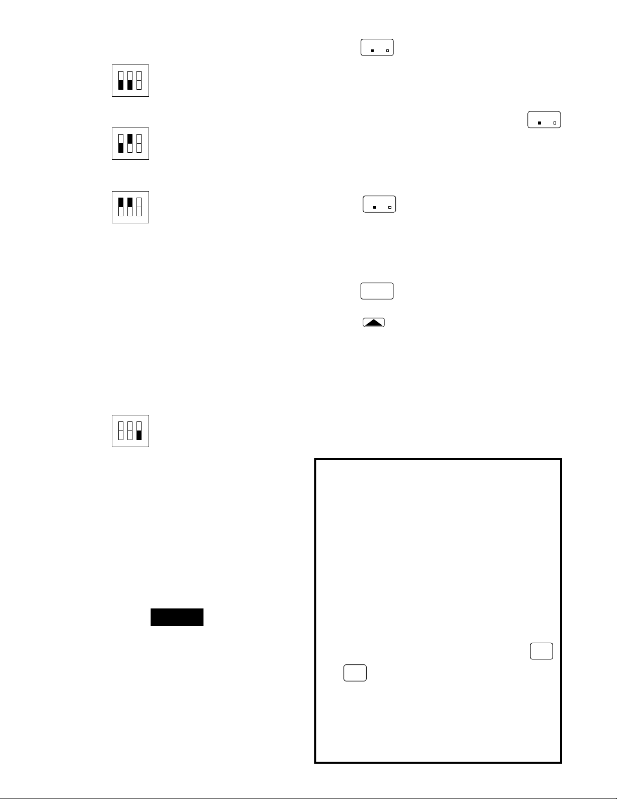
1. Press
SYSTEM
HEAT-OFF-COOL-AUTO
until COOL is displayed.
2. Press to adjust thermostat below room tem-
perature to call for cool. The blower should come on
immediately, followed by cold air circulation. How-
ever,iftheredLEDonthethermostatfrontisflashing,
the compressor lockout feature is operating (see
Lockout Bypass Option to temporarily override the
compressor lockout feature during testing).
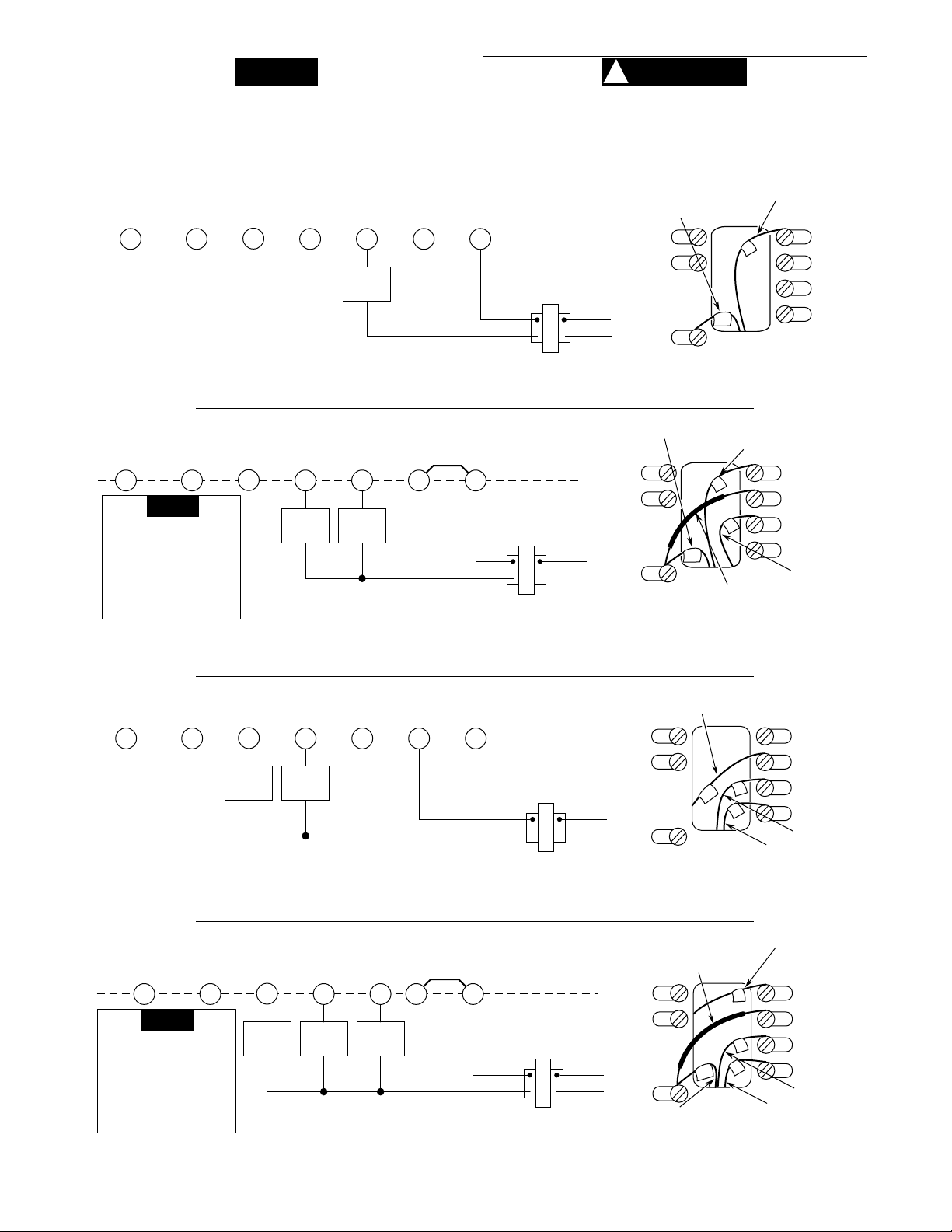
Ifthethermostatdisplayisoperatingproperly,butthe
cooling system does not operate when the above
steps are performed, the red jumper wire (provided
with thermostat) may not be properly installed be-
tween the RH and RC terminals. Disconnect electri-
cal power to system and properly install the jumper
wire per the appropriate wiring diagram.
After the system has been checked and is running prop-
erly, determine if automatic changeover is desired (see
SYSTEM CONFIGURATION).
Refer to the OPERATION GUIDE if you need additional
information on thermostat operation.
TROUBLESHOOTING
Refer to the Question & Answer section of the OPERA-
TION GUIDE for information on troubleshooting the ther-
mostat.
WARRANTY INFORMATION
THISWARRANTYSTATEMENTSUPERSEDESALLWARRANTY
STATEMENTS DATED PRIOR TO MARCH 1, 1988.
White-Rodgers Division of Emerson Electric Co. (“Seller”) war-
rantsthat itsproducts purchased for resale (the“Products”) willbe
free from defects in material and workmanship under normal use
and service for a period of twelve (12) months from date of
installation. Seller’sobligationunderthiswarranty,andPurchaser’s
exclusive remedy for the breach thereof, shall be limited to, at
Seller’s option, Seller’s replacement of any defective Product
F.O.B.Seller’sfactory,orSeller’sissuanceofacreditintheamount
of the purchase price of such Product for resale as described
below. Seller shall have the option of requiring the return of any
defective Product, transportation charges prepaid, before recog-
nizing any claim. This warranty shall not apply to any Product (1)
which has been repaired or altered outside Seller’s factory or by
other than Seller in any manner so as, in Seller’s judgement, to
affect its serviceability or proper operation; (2) which has been
subjected by persons other than Seller to improper handling,
operation,maintenance,repairoralteration; or (3)whichhasbeen
subjected to misuse, negligence, or accident.
This warranty extends only to persons or organizations who
purchase the Products for resale. THE FOREGOING CONSTI-
TUTESSELLER’SSOLERESPONSIBILITYUNDERTHISWAR-
RANTY, AND PURCHASER’S EXCLUSIVE REMEDY FOR
BREACH THEREOF. EXCEPT AS OTHERWISE EXPRESSLY
SET FORTH IN THIS AGREEMENT, THERE ARE NO OTHER
WARRANTIES, EXPRESS OR IMPLIED, WHETHER OF MER-
CHANTABILITY,FITNESSFORAPARTICULARPURPOSE,OR
OTHERWISE. SELLER SHALL NOT BE LIABLE FOR ANY
SPECIAL,INDIRECT,INCIDENTALORCONSEQUENTIALDAM-
AGESINCONNECTIONWITH THE SALE,RESALEORUSEOF
THE PRODUCTS.
Complete warranty information and instructions for replacing/
returning warranty products can be found in the White-Rodgers
Product Catalog, or by telephoning or writing to:
White-Rodgers Division
Emerson Electric Co.
9797 Reavis Road
St. Louis, Missouri 63123-5329
(314) 577-1300
WARRANTY INFORMATION FOR CONSUMERS
When you purchase a White-Rodgers Division product, it is typi-
cally for replacement of a device which has failed on existing
residential or commercial equipment, or a component of new
equipment purchased for modernization.
While our warranty does not extend to you, your contractor or
dealer is protected by a one-year product warranty from White-
Rodgers. Your supplier can rely on a nearby White-Rodgers
wholesaler for prompt credit or replacement.
CAUTION
!
If you need further information about this product, please write to:
WHITE-RODGERS
Division of Emerson Electric Co.
9797 Reavis Road
St. Louis, MO 63123
ATTN: Technical Service Department
Other manuals for 1F90W-71
1
Table of contents