Wine Guardian CS050 Instruction Manual

2
Wine Guardian Ceiling System
This document is a pictorial guide for installing the Wine Guardian
Ceiling system. It is not intended to replace the detailed instructions
found in the Installation, Operation and Maintenance (IOM) manual,
which includes important safety messages all installers and owners
should follow for safe and optimal performance of the system.
Complete IOM manuals can be found on the Resources and Manuals
page of wineguardian.com. If you have additional questions related to
your Wine Guardian Ceiling System, please contact our authorized Wine
Guardian distributor or your local Wine Guardian office.
Please fill out the WG Split System start-up checklist that can be
found by downloading the full Installation, Operation, and
Maintenance manual from our website, for your model split
system.
English ............................................ page 3
Deutsch............................................ Seite 8
Español ...................................... página 14
Français .........................................page 20
中文 ....................................................页 26
Pусский .................................. cтраница 32
Product overview & Options ............page 38
....................................................................

3
1. Unpackage
A. Remove unit from box. Check for any signs of
concealed damage, and that all optional equipment
has been provided. Contact Air Innovations
immediately if components are missing or/if unit has
been damaged in shipping.
B. Shipment includes:
- One (1) Fan-coil unit
- One (1) Mounting flange
- One (1) Supply/Return Grille Assembly
- One (1) Condensing unit
- One (1) remote interface controller with 50’ control
cable
- One (1) Documentation Bag with auxiliary data plate
Humidification — Stand-alone
Ideal for adding humidity to your wine cellar.
Temperature / Humidity Remote Sensors
Sense and control multiple locations (maximum
of three) within your room. Ideal for odd shaped
rooms or multi-room applications.

4
2. Installing the Fan-Coil
Decide where the unit will be mounted, consider the
supply/return orientation, to ensure the utilities can be
connected to the correct side of the unit. The Ceiling
System consists of a Fan-coil Chassis, a Mounting
Flange, and a Diffuser (Fig. 1). The fan coil unit can be
located either above, or below the condensing unit in
height. Keep any height difference to a maximum of
15’ (4.57meters).
Mounting The Fan-Coil
A. Cut an opening in the ceiling 41” long x 14.5” wide
16” on center joists, or 41” long x 10.5” wide for a
12” on center joist spacing (Fig. 2).
B. Install the mounting flange onto the ceiling and
secure it to the joists using 2 1/2” flat head wood
construction screws (not provided). Ensure the hinge
area of the mounting flange is opposite the utility
connection side of the unit (Fig. 3).
C. Connect the fan-coil to the hinge of the mounting
flange (Fig. 4), swing the unit up and connect the fan
-coil to the mounting flange using four (4) washers,
lock washers, and nuts (Provided) (Fig. 5).
D. Connect all the utilities to the fan-coil. See the
complete Manual for instructions on how to
implement the provided Swage Locks (Page 35).
ATTENTION
E. After all utilities are connected, fill in any voids or
holes around unit including utility connection area
with insulation.
F. Attach the diffuser to the mounting bracket using the
hinges on the diffuser and flange and lock the
diffuser into place using the mounting clips (Fig. 6).
Fig. 1
Fig. 2
Fig. 3
Fig. 4
Fig. 5
Fig. 6

5
4. Condensate Drain
A. Wine Guardian ceiling systems come equipped
with a condensate pump system. Connect the
drain line to the barbed fitting at the unit and run
the drain line to the nearest drain location.
3. Installing Thermostat (Wired)
A. Unit is supplied with 50 feet (15 meters) of cable
with RJ-9 type connection to the Remote User
Interface Controller.
B. Disconnect wire from back of controller and route
the cable to the desired mounting location within
the room.
C. Locate Remote User Interface within the room
midpoint on a wall in an area with good airflow
and away from any windows or heat sources.
D. Remove back plate of controller and mark
mounting points at desired location.
E. Drill two 1/8” (3 mm) holes and insert anchors
within mounting surface. Anchors may not be
required if securing to wall studs or racking.
Insert screws into the anchors and test fit the
installation of the backing plate tighten/loosen
screws to create a snug fit.
F. Provide 3/4” (19 mm) diameter hole within wall or
racking structure to provide clearance for RJ-9
connection at the back of the controller.
G. Re-attach front cover plate by screwing it into
place on the back plate.
H. Connect RJ-9 cable to the back of the remote
user interface and attach to the wall at the screw
locations
I. Reconnect cable to side of Wine Guardian unit at
either COM1 or COM2.
Note: For wireless installations or multiple
remote interfaces, refer to the full version manual
located at wineguardian.com/manuals

6
MODEL LIQUID LINE (OD) SUCTION LINE (OD)
CS025
CS050 / WGC60
1/4 inch
1/4 inch / 0.635 cm
3/8 inch
1/2 inch / 1.27 cm
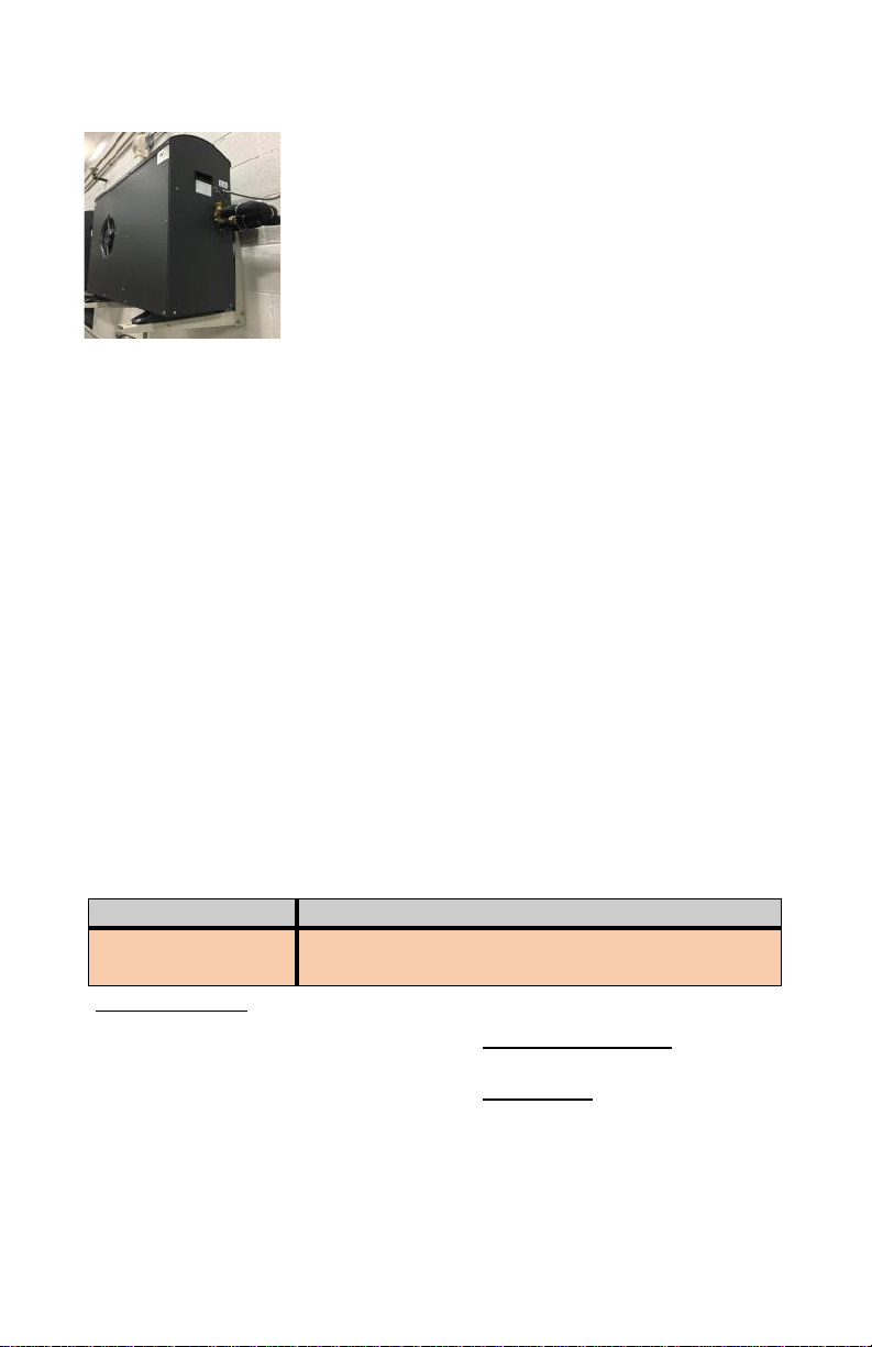
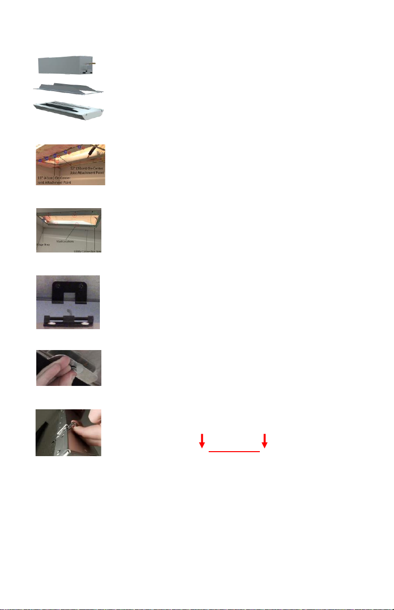
5. Installing the Condensing Unit
A. Wine Guardian condensing unit must be mounted
horizontally on its base as shown and be level to
+/- ¼” end to end and 1/8” side to side.
B. A minimum of 12 inches is required around the
perimeter of the condensing unit for proper
airflow across the unit and for service access.
C. Provide a half-inch downward slope in suction and liquid line toward the
condenser for every 10 feet of line-set to prevent an oil return issue from
occurring. This will allow oil in the system to return to the compressor
when the system is off to ensure the system remains lubricated.
D. Mount system on concrete slab outside above average snow fall heights.
Unit can also be mounted to side of house or within a large indoor crawl
space, attic, or mechanical room that is at least three (3) times the size of
the cellar.
E. Prevent dips, sags, or other low spots that will trap refrigerant oil.
F. Evacuate and leak test indoor unit suction and liquid lines by purging the
dry air charge from the unit by opening the liquid line shut-off valve or
removing the liquid line outlet fitting or plug, whichever is applicable for
your unit.
G. Pressurize and leak test system (the condensing unit comes pre charged).
A pressure equal to the low side test pressure marked on the unit
nameplate is recommended for leak testing.
H. Evacuate the system to hold at 500 microns and break the vacuum with
refrigerant. Charge the system with the correct amount of refrigerant and
mark the amount, with a permanent marker in the space provided on the
unit nameplate. (See chart on below)
I. See the full Wine Guardian Operations and installation manual for
comprehensive charging procedure. At www.wineguardian.com. Includes
charts for system Pressures, Superheat, and Sub-cooling.
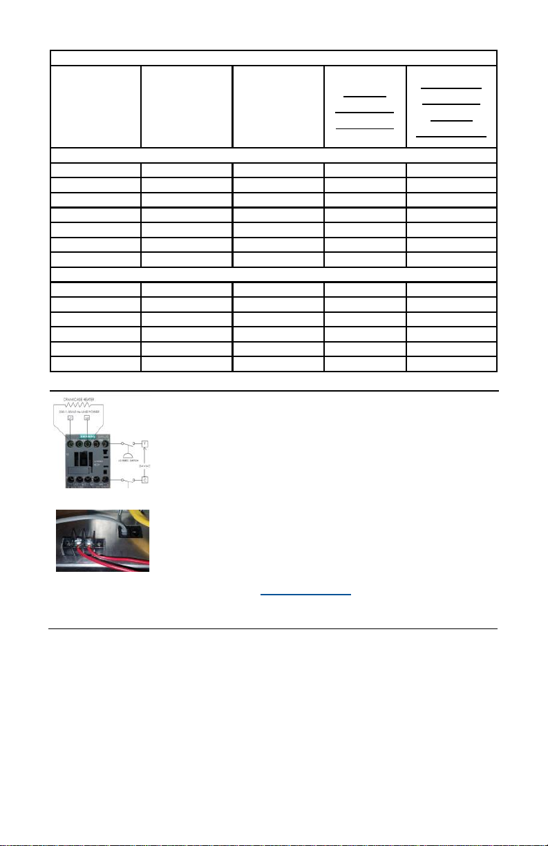
System Charging
For Installations using a line-set distance that are Less Than or Equal To 25’ add the
required amount of refrigerant shown in the table above.
For Installations using a line-set distance that are Greater Than 25’ add the required
amount of refrigerant shown in the table above THEN add additional refrigerant based on
the rules below:
Models SS018, CS025, DS025, CS050, DS050, WGS25, WGC60, WGS40, and WGS75
Add an additional 0.50 oz/ft (0.465 kg/meter) for every foot exceeding 25’
Models DS088, DS200, WGS100, and WGS175
Add an additional 1 oz/ft (0.93 kg/meter) for every foot exceeding 25’

7
7. Turn Unit On
A. Turn on power to the Fan-coil. Press the “On/Off” button on the Remote
User Interface. The Remote User Interface is preset to a room
temperature of 55°F (13°C).
B. Press the “Up” arrow once. The display will show the existing
temperature setpoint. Press the “up or down” arrow buttons to adjust the
temperature to the desired setpoint.
C. The system will turn on after a 5-minute time delay and the cold air
section will start to deliver cold air. Contact Air Innovations if the system
fails to turn on.
6. Wiring the Unit for Power
A. Connect line power to the contactor inside the
condensing unit as shown.
B. Run 24 volt low voltage signal wires from Y and C
terminals on fan coil to Y and C connections in
condenser housing (shown in image to the left).
C. Turn on power to the condensing unit 24 hours prior to
system start-up to allow crankcase heater to warm up
compressor.
*See page 20 in owners manual for full wiring
schematic. Inside of condensing unit also contains
schematic.
Assuming a 25’ Line-Set Installation
Model # Total Charge
Required
Holding
Charge
Present
Charge
That Must
Be Added
Additional
Charge to
add for
XLA1 option
60Hz Models
SS018 47 oz 16 oz 31 oz 4 oz
CS025 58 oz 16 oz 42 oz 4 oz
DS025 59 oz 16 oz 43 oz 4 oz
CS050 66 oz 16 oz 50 oz 4 oz
DS050 55 oz 16 oz 39 oz 4 oz
DS088 105 oz 16 oz 89 oz 6 oz
DS200 108 oz 16 oz 92 oz 6 oz
50Hz Models
WGS25 50 oz 16 oz 34 oz 4 oz
WGC60 64 oz 16 oz 48 oz 4 oz
WGS40 58 oz 16 oz 42 oz 4 oz
WGS75 64 oz 16 oz 48 oz 4 oz
WGS100 106 oz 16 oz 90 oz 6 oz
WGS175 110 oz 16 oz 94 oz 6 oz
1XLA – Extreme Low Ambient Opon

8
Deutsch
Deckensystems von Wine Guardian
Dieses Dokument ist eine bildliche Anleitung für die Montage
des Deckensystems von Wine Guardian. Diese Anleitung soll
nicht die detaillierten Anweisungen des Installations-, Be-
dienungs- und Wartungshandbuchs (IBW) ersetzen, das
wichtige Sicherheitsinformationen enthält, die alle Installateure
und Besitzer für einen sicheren und optimalen Betrieb des Sys-
tems beachten sollten.
Vollständige IBW-Handbücher finden Sie auf der Seite
Ressourcen und Handbücher von wineguardian.com. Wenn
Sie weitere Fragen zu Ihrem Wine Guardian Deckensystem
haben, kontaktieren Sie bitte Ihren autorisierten Wine Guardi-
an-Vertriebspartner oder Ihr lokales Wine Guardian-Büro.
Bitte füllen Sie die Checkliste zur Inbetriebnahme für das WG
Split-System aus, die Sie beim Herunterladendes vollständigen
Installations-, Betriebs- und Wartungshandbuch für unser Modell-
Split-System auf unserer Website finden

9
Befeuchtung — Stand-Alone
Ideal, um Ihrem Weinkeller Feuchtigkeit hinzuzufügen.
Temperatur-/Feuchtigkeitsaußensensoren
Erfassen und steuern Sie mehrere Standorte (maximal
drei)
in Ihren Räumlichkeiten. Ideal für ungewöhnlich
geformte Räume oder Multi-Raum-Anwendungen.
Feuchtigkeit hinzuzufügen.
1. Auspacken
A. Einheit aus der Verpackung entnehmen. Über-
prüfen Sie alle Anzeichen von verdeckten Schäden,
und ob alle optionalen Geräte zur Verfügung
gestellt wurden. Kontaktieren Sie Air Innovations
sofort, wenn Komponenten fehlen oder wenn das
Gerät beim Versand beschädigt wurde.
B. Lieferung enthält:
- Eine (1) Gebläsekonvektoreneinheit
- Ein (1) Montageflansch
- Eine (1) Vor- / Rücklaufgitterbaugruppe
- Eine (1) Kondensatoreinheit
- Ein (1) Remote-Schnittstellen-Controller mit 127-
cm- Steuerkabel
- Ein (1) Dokumentationstasche mit
Zusatzdatenschild

10
2. Montage des Gebläsekonvektors
Legen Sie fest, wo das Gerät montiert werden soll, und
achten Sie auf die Ausrichtung von Vor- und Rücklauf, um
sicherzustellen, dass die Versorgungsleitungen an der richti-
gen Seite des Geräts angeschlossen werden können. Das
Deckensystem besteht aus einem Gebläsekonvektor, einem
Montageflansch und einem Vor- / Rücklaufgitter (Abb. 1).
Die Gebläsekonvektoreneinheit kann entweder über oder
unter der Höhe der Kondensatoreinheit platziert werden. Der
Höhenunterschied sollte nicht mehr als 4,57 Meter (15“)
betragen.
Montage des Gebläsekonvektors
A. Schneiden Sie eine Öffnung in die Decke, 104,1 cm
lang x 36,8 cm breit, für 40,6 cm Abstand zwischen den
Mittelträgern, oder 104,1 cm lang x 26,7 cm breit, für
30,5 cm Abstand zwischen den Mittelträgern (Abb. 2).
B. Bringen Sie den Montageflansch an der Decke an und
befestigen Sie ihn mit 2 1/2”-Holzschrauben (nicht im
Lieferumfang enthalten ) an den Trägern. Stellen Sie
sicher, dass der Scharnierbereich des Mon-
tageflansches gegenüber der Netzanschlussseite des
Geräts liegt (Abb. 3).
C. Verbinden Sie den Gebläsekonvektor mit dem
Scharnier des Montageflansches (Abb. 4), schwenken
Sie das Gerät nach oben und verbinden Sie den
Gebläsekonvektor mit vier (Abb. 4) Unterlegscheiben,
Sicherungsscheiben und Muttern (mitgeliefert) (Abb. 5).
D. Schließen Sie alle Netzteile an den Gebläsekonvektor
an. Anweisungen zum Anschließen der Swagelock-
Verschraubungen (Seite 35) finden Sie im vollständigen
Handbuch.
ATTENTION
E. Füllen Sie nach dem Anschließen aller Netzteile alle
Hohlräume oder Löcher um das Gerät einschließlich
des Netzanschlussbereichs mit Isolierung aus.
F. Befestigen Sie den Diffusor an der Montagehalterung,
indem Sie die Scharniere am Diffusor mit dem Flansch
verbinden und den Diffusor mit den Montageklammern
Abb. 1
Abb. 2
Abb. 3
Abb. 4
Abb. 5
Abb. 6

11
3. Thermostat verkabeln
A. Das Gerät wird mit einem 15 Meter langen Kabel mit
RJ-9- Anschluss für den Remote-Schnittstellen-
Controller geliefert.
B. Trennen Sie das Kabel von der Rückseite des
Controllers und verlegen Sie es zum gewünschten
Montageort im Raum.
C. Platzieren Sie die Remote-Schnittstelle im Raum mittig
auf einer Wand in einem Bereich mit guter
Luftzirkulation und entfernt von allen Fenstern oder
Wärmequellen
D. Entfernen Sie die Rückplatte des Controllers und
markieren Sie die Montagepunkte am gewünschten
Montageort.
E. Bohren Sie zwei 3 mm (1/8“) große Löcher und führen
Sie die Dübel in die Montageoberäche ein. Dübel
sind nicht erforderlich, wenn sie an einem Wand-
oder Regalsystem befesgt werden. Setzen Sie die
Schrauben in die Dübel ein und testen Sie die
Installaon der Rückplae. Ziehen Sie die Schrauben
an/ lösen, um einen festen Halt zu erzielen.
E. Bringen Sie ein Loch mit einem Durchmesser von 19
mm in der Wand oder in der Regalstruktur an, um
Platz für den RJ-9-Anschluss an der Rückseite des
Controllers zu ermöglichen.
F. Bohren Sie ein Loch mit einem Durchmesser von 19
mm in die Wand oder in die Regalkonstrukon, um
Platz für den RJ-9-Anschluss an der Rückseite des
Controllers zu erreichen..
G. Verbinden Sie das RJ-9-Kabel an der Rückseite der
Remote-Schnistelle an und befesgen Sie es an den
Verschraubungen an der Wand.
H. Verbinden Sie erneut das RJ-9-Kabel mit der Seite der
Wine Guardian-Einheit entweder mit COM1 oder
COM2 .
4. Kondensatablauf
A. Wine Guardian-Deckensysteme sind mit einem
Kondensatpumpensystem ausgestattet.
Schließen Sie die Ablaufleitung am Gerät an und
führen Sie sie zum nächsten Ablaufort.

12
Systemaufladung
Hinweis: Jede Kondensationseinheit des DS & WGS-Modells wird bereits mit einer
Kältemittelfüllung von 0,453 kg (16 oz) geliefert, die bei den unten angegebenen
Gesamtmengen, basierend auf der Verbindungslänge von 7,62 m (25 Zoll), zu
berücksichtigen ist.
** Passen Sie für jede Rohrleitung, die 1 Fuß oder 1 Meter mehr oder weniger lang
ist als 25 Fuß / 7,62 Meter, die Gesamtmenge des Kältemiels R134A des Systems
entsprechend der Basisleitung um 0,0465 kg an.”
MODELL FLÜSSIGKEITSLEITUNG
(OD) SAUGLEITUNG (OD)
CS025
CS050 / WGC60 1/4 Zoll
1/4 Zoll / 0.635 cm
3/8 Zoll
1/2 Zoll / 1.27 cm
C. Sorgen Sie für ein Gefälle von 1,25 cm in der Saug- und Flüssigkeitsleitung
zum Kondensator alle 3 Meter des Leitungssatzes, um ein Problem mit der
Ölrückführung zu vermeiden. Dadurch kann Öl im System zum
Kompressor zurückkehren, wenn das System ausgeschaltet ist, um
sicherzustellen, dass das System geschmiert bleibt.
D. Montieren Sie das System auf einer Betonplatte außerhalb
überdurchschnittlicher Schneefallhöhen. Das Gerät kann auch auf der
Seite des Hauses oder in einem großen Kriechkeller im Haus, auf dem
Dachboden oder in einem Maschinenraum, der mindestens drei (3) Mal
größer ist als der Keller, montiert werden.
E. Verhindern Sie Vertiefungen, Absenkungen oder andere niedrige Stellen,
an denen sich das Kältemittel-Öl ansammeln kann.
F. Entleeren Sie die innere Saugeinheit und Flüssigkeitsleitungen und prüfen
Sie diese auf Dichtigkeit, indem Sie die Trockenluftfüllung aus dem Gerät
durch Öffnen der Absperrklappe der Flüssigkeitsleitung oder Entfernen der
Flüssigkeitsauslaufarmatur oder -stopfen, je nachdem, was für Ihr Gerät
zutrifft, ablassen .
G. Setzen Sie das System unter Druck und prüfen Sie es auf Dichtigkeit (der
Kondensator wird vorab aufgeladen geliefert). Für die Dichtigkeitsprüfung
wird ein Druck empfohlen, der dem auf dem Typenschild des Geräts
markierten niedrigen Prüfdruck entspricht.
H. Leeren Sie das System, um es bei 500 Mikron zu halten und brechen Sie
das Vakuum mit dem Kältemittel. Befüllen Sie das System mit der richtigen
Menge an Kältemittel und markieren Sie den Wert mit einem
Permanentmarker in dem auf dem Typenschild des Gerätes vorgesehenen
Feld. (siehe Tabelle unten)
I. Die ausführlicheWine Guardian Betriebs- und Montageanleitung für mehr
Informationen finden Sie unter
5. Montage der Kondensatoreinheit
A. Die Wine Guardian Kondensatoreinheit muss
horizontal wie abgebildet auf ihren Sockel montiert
werden und muss vorne und hinten +/- 0,635 cm und
0,1375 cm an den Seiten haben.
B. Ein Mindestabstand von 30 cm um
dieKondensatoreinheit ist für eine ordnungsgemäße
Luftzirkulation im Gerät und den Servicezugang,
erforderlich.

13
7. Einheit einschalten
A. Schalten Sie den Gebläsekonvektor ein. Drücken Sie die „Ein / Aus“-Taste auf der
Remote-Benutzeroberfläche. Die Remote-Benutzeroberfläche ist auf eine
Raumtemperatur von 13° C voreingestellt.
B. Drücken Sie einmal auf die Pfeiltaste nach oben. Das Display zeigt den aktuellen
Temperatursollwert an. Drücken Sie die Pfeiltaste nach oben oder nach unten, um die
Temperatur auf den gewünschten Sollwert einzustellen.
C. Das System schaltet sich nach einer Verzögerung von 5 Minuten ein und der Kalt-
luftbereich beginnt mit der Abgabe von Kaltluft. Kontaktieren Sie Air Innovations, wenn
sich das System nicht einschalten lässt.
6. Anschluss des Gerät an die Stromversorgung
A. Verbinden Sie die Stromleitung wie abgebildet mit dem Konden-
sator.
B. Lassen Sie die 24-Volt-Niederspannungssignalkabel von den Y-
und C- Klemmen auf dem Gebläsekonvektor bis zu den Y- und
C- Anschlüssen im Kondensatorgehäuse laufen (Abbildung
links).
C. Schalten Sie die Kondensatoreinheit 24 Stunden vor dem Sys-
temstart ein, damit der Kurbelgehäuseheizer den Kompressor
aufwärmen kann.
*Siehe Seite 20 in dem Benutzerhandbuch für mehr Details. Die
Innenseite des Kondensators enthält auch einen Schaltplan.
Angenommen, eine Installation mit 25’ Zeilen
Modell # Erforderliche
Gesamtgebuhr Haltegebühr
vorhanden
Gebühr, die
hinzugefügt
werden muss
Zusätzliche
Gebühr hin-
zuzufügen
für XLA1
option
60Hz Models
SS018 47 oz 16 oz 31 oz 4 oz
CS025 58 oz 16 oz 42 oz 4 oz
DS025 59 oz 16 oz 43 oz 4 oz
CS050 66 oz 16 oz 50 oz 4 oz
DS050 55 oz 16 oz 39 oz 4 oz
DS088 105 oz 16 oz 89 oz 6 oz
DS200 108 oz 16 oz 92 oz 6 oz
50Hz Models
WGS25 50 oz 16 oz 34 oz 4 oz
WGC60 64 oz 16 oz 48 oz 4 oz
WGS40 58 oz 16 oz 42 oz 4 oz
WGS75 64 oz 16 oz 48 oz 4 oz
WGS100 106 oz 16 oz 90 oz 6 oz
WGS175 110 oz 16 oz 94 oz 6 oz
1XLA – Extrem niedrige Umgebungsbedingungen

14
Español
Sistema Wine Guardian para techos
Este documento es una guía ilustrada para la instalación del
sistema Wine Guardian para techos. No se pretende
reemplazar las instrucciones detalladas que se encuentran
en el manual sobre Instalación, Operación y Mantenimiento
(IOM), el cual incluye importantes mensajes de seguridad
que todos los instaladores y propietarios deberían seguir para
usarlo de manera segura y para que el sistema tenga un
rendimiento óptimo.
Los manuales completos sobre IOM se pueden encontrar en
la página de Recursos y Manuales de wineguardian.com. Si
tiene preguntas adicionales relacionadas con el sistema Wine
Guardian para techos, por favor, póngase en contacto con
nuestro distribuidor autorizado de Wine Guardian o con la
oficina local de Wine Guardian.
Complete la lista de verificación de inicio del sistema WG
Split que se puede encontrar descargando el manual
completo de instalación, operación y mantenimiento de
nuestro sitio web, para su modelo de sistema dividido

15
Humidificación —Unidad independiente
Ideal para aportar humedad a su bodega.
Sensores remotos de temperatura/humedad
Detecte y controle múltiples ubicaciones (máximo tres)
dentro de la habitación. Ideal para espacios con formas
irregulares o instalaciones en múltiples lugares.
1. Extracción del embalaje
A. Extraiga la unidad de la caja. Compruebe que no
haya daños ocultos y que cuente con todo el
equipamiento opcional. Póngase en contacto
inmediatamente con Air Innovations si faltan
componentes o si la unidad sufrió algún daño
durante el envío.
B. El paquete incluye:
- Una (1) unidad ventiloconvectora
- Una (1) brida de fijación
- Una (1) rejilla de suministro/retorno protectora
- Una (1) unidad de condensación
- Un (1) controlador de interfaz remota con cable
de control de 50’
- Una bolsa (1) con documentación y una placa de
datos auxiliar

16
2. Instalación del ventiloconvector
Decida dónde se instalará la unidad, tenga en cuenta la
orientación del suministro/retorno para asegurar que los
módulos se puedan conectar del lado correcto de la unidad. El
sistema para techos consta de un ventiloconvector, una brida
de fijación y una rejilla de suministro/retorno (Fig. 1). El
ventiloconvector puede ser colocado ya sea por encima o por
debajo de la unidad de condensación. Mantenga cualquier
diferencia de altura en un máximo de hasta 15’ (4,57 metros).
Montaje del ventiloconvector
A. Haga una apertura en el techo de 41" de largo x
14.5" de ancho para 16" en el centro de la
separación entre vigas, o 41" de largo x 10.5" de
ancho para 12" en el centro de la separación entre
vigas (Fig. 2).
B. Coloque la brida de fijación en el techo y afiáncela
en la viga mediante tornillos para construcciones
de madera de cabeza plana 2 1/2” (no incluidas).
Asegúrese de que el área de la bisagra para la
brida de fijación se encuentre en posición opuesta
al lado de la unidad para conexión de módulos
(Fig. 3).
C. Conecte el ventiloconvector a la bisagra de la brida
de fijación (Fig. 4), gire la unidad hacia arriba y
conecte el ventiloconvector a la brida de fijación
mediante cuatro (4) arandelas, arandelas de
retención y tuercas (incluidas) (Fig. 5).
D. Conecte todos los módulos al ventiloconvector.
Consulte el manual completo para obtener
instrucciones sobre cómo conectar los racor de
retención de plataforma (página 35).
ATENCIÓN
E. Después de que todos los módulos hayan sido
conectados, llene los huecos o espacios alrededor
de la unidad, incluyendo el área de conexión de los
módulos con aislamiento.
F. Fije el difusor al soporte de montaje conectando
las bisagras del difusor a la brida y trabe el difusor
en su ubicación mediante los ganchos de montaje
(Fig. 6).
Figura 1
Figura 2
Figura 3
Figura 4
Figura 5
Figura 6

17
3. Instalación del termostato (cableado)
A. La unidad viene con 50 pies (15 metros) de cable
con conexión de tipo RJ-9 junto con el controlador
de interfaz remota para usuarios.
B. Posicione la interfaz remota para usuarios en el
medio de una pared que se encuentre en un área
con buen flujo de aire y apartada de ventanas o
fuentes de calor.
C. Desconecte el cable de la parte posterior del
controlador y dirija el cable a la ubicación deseada
para el montaje dentro de la habitación.
D. Haga un orificio de 3/4” (19 mm) de diámetro en la
pared o estanterías para que quede un espacio libre
para el enrutamiento de la conexión RJ-9 en la parte
posterior del controlador.
E. Retire la placa posterior del controlador y marque
los puntos de montaje en la ubicación deseada.
F. Taladre dos orificios de 1/8” (3 mm) e inserte los
anclajes dentro de la superficie de montaje. Es
posible que no se requieran anclajes si se fijan a
montantes de pared o estanterías. Introduzca
tornillos en los anclajes y pruebe el ajuste del
montaje de la placa de apoyo. Apriete/afloje los
tornillos hasta alcanzar un ajuste óptimo.
G. Vuelva a colocar la cubierta frontal en la placa
posterior atornillándola en su lugar.
H. Conecte el cable RJ-9 a la parte posterior de la
interfaz remota para usuario y acóplela a la pared
en las posiciones de los tornillos.
I. Vuelva a conectar el cable RJ-9 en el lateral de la
unidad Wine Guardian ya sea a COM1 o COM2.
Nota: Para instalaciones inalámbricas o múltiples
interfaces remotas, consulte la versión completa del
manual que se encuentra en wineguardian.com/
manuals
4. Drenaje de condensación
A. Los sistemas Wine Guardian para techos vienen
equipados con un sistema de bombeo de
condensación. Conéctelo a la línea de drenaje de la
unidad y diríjalo hacia el sumidero más cercano.

18
Carga del sistema
Nota: Cada unidad condensadora de los modelos DS y WGS ya se envía con 16 oz/0,453 kg de
carga de refrigerante, que debe tenerse en cuenta para las cantidades totales inferiores
basadas en una longitud de interconexión de 25 pies/7,62 metros.
** Por cada 1 pie o 1 metro más o menos de tubería de 25 pies/7,62 metros, ajuste la carga
total de refrigerante R134A del sistema a parr de la línea de base anterior en
0,50 oz/0,0465 kg.
MODELO LÍNEA DE FLUIDO (OD) LÍNEA DE SUCCIÓN (OD)
CS025
CS050 / WGC60
1/4 pulgada
1/4 pulgada / 0.635 cm
3/8 pulgada
1/2 pulgada / 1,27 cm
C. Proporcione una pendiente descendente de 1,25 centímetros en la línea de
succión y líquido hacia el condensador por cada 3 metros de juego de
líneas para evitar que ocurra un problema de retorno de aceite. Esto
permitirá que el aceite en el sistema regrese al compresor cuando el
sistema esté apagado para garantizar que el sistema permanezca
lubricado.
D. Monte el sistema en una placa de hormigón en el exterior y por encima de
la altura media alcanzada por las nevadas. La unidad también se puede
instalar en el lateral de una casa o dentro de un gran semisótano, ático o
cuarto con maquinaria que tenga, al menos, tres (3) veces el tamaño de la
bodega.
E. Evite inmersiones, hundimientos u otros puntos bajos que retengan el
aceite refrigerante.
F. Vacíe y examine las posibles fugas de las líneas de succión y fluido de la
unidad de interior purgando la carga de aire seco de la unidad abriendo la
válvula de paso de la línea de fluido, o retirando el conector o el enchufe
de salida de la línea de fluido, según lo que corresponda a su unidad.
G. Sistema de prueba de presurización y fugas (la unidad de condensación
viene precargada). Se recomienda una presión igual a la presión inferior de
prueba marcada en la placa de identificación de la unidad para pruebas de
fuga.
H. Vacíe el sistema para mantenerlo a 500 micras y rompa el vacío con
refrigerante. Cargue el sistema con la cantidad correcta de refrigerante y
anote la cantidad con un marcador permanente en el espacio provisto en la
placa de identificación de la unidad (consulte el cuadro a continuación).
I. Consulte el manual completo de operaciones e instalación de Wine
Guardian para conocer el procedimiento completo de carga.
5. Instalación de la unidad de condensación
A. La unidad de condensación de Wine Guardian debe
montarse horizontalmente en su base, tal y como se
muestra, y estar nivelada a +/- ¼" de extremo a ex-
tremo y 1/8" de lado a lado.
B. Se requiere un mínimo de 12 pulgadas alrededor del
perímetro de la unidad de condensación para que el
aire fluya de manera adecuada a través de la unidad
y para acceder a realizarle el mantenimiento.

19
7. Encenddo de la unidad
A. Encienda la alimentación hacia el ventiloconvector. Presione el botón “On/
Off” en la interfaz para usuario remota. La interfaz para usuario remota
viene preconfigurada a una temperatura ambiente de 55 °F (13 °C).
B. Presione la flecha "Arriba" una vez. La pantalla mostrará el valor de
temperatura de referencia existente. Presione las flechas "arriba o abajo"
para ajustar la temperatura hasta el valor de referencia deseado.
C. El sistema se encenderá después de 5 minutos y la sección de aire frío
comenzará a suministrar aire frío. Póngase en contacto con Air
Innovations si el sistema no se enciende.
6. Cableado de la unidad para alimentación eléctrica
A. Conecte la línea de alimentación al contactor dentro
de la unidad de condensación tal y como se muestra.
B. Lleve los cables marcados con las señales de bajo
voltaje (24 voltios) desde las terminales Y y C en el
ventiloconvector hacia las conexiones Y y C en la
carcasa del condensador (como se muestra en la
imagen a la izquierda).
C. Encienda la unidad de condensación 24 horas antes
del arranque del sistema para permitir que la resisten-
cia del cárter caliente el compresor.
*Consulte la página 20 del manual de usuario para ver
el esquema completo del cableado. El interior de la
unidad de condensación también contiene esquemas.
Suponiendo una instalación de conjunto de líneas de 25'
Modelo # Cargo total
requerido
Cargo de
retención
presente
Cargo que
hay que
añadir
Cargo adi-
cional para
agregar
XLA1 option
60Hz Models
SS018 47 oz 16 oz 31 oz 4 oz
CS025 58 oz 16 oz 42 oz 4 oz
DS025 59 oz 16 oz 43 oz 4 oz
CS050 66 oz 16 oz 50 oz 4 oz
DS050 55 oz 16 oz 39 oz 4 oz
DS088 105 oz 16 oz 89 oz 6 oz
DS200 108 oz 16 oz 92 oz 6 oz
50Hz Models
WGS25 50 oz 16 oz 34 oz 4 oz
WGC60 64 oz 16 oz 48 oz 4 oz
WGS40 58 oz 16 oz 42 oz 4 oz
WGS75 64 oz 16 oz 48 oz 4 oz
WGS100 106 oz 16 oz 90 oz 6 oz
WGS175 110 oz 16 oz 94 oz 6 oz
1XLA – Opción de ambiente extremadamente bajo

20
Français
Système Wine Guardian Ceiling
Ce document est un guide illustré pour l’installation de votre
climatiseur Wine Guardian Ceiling. Il n’est pas destiné à
remplacer les instructions détaillées du manuel d’installation,
d’utilisation et d’entretien, lequel comprend d’importants
messages de sécurité que toute personne installant ou
possédant ce système doit suivre pour garantir le
fonctionnement sûr et optimal du climatiseur.
Vous trouverez les manuels d'installation et d’utilisation complets
sur la page Ressources et manuels de wineguardian.com. Pour
toute autre question concernant votre climatiseur Wine Guardian
Ceiling, veuillez contacter votre distributeur Wine Guardian
agréé ou votre filiale Wine Guardian locale.
Veuillez remplir la liste de contrôle de démarrage du WG Split
System qui peut être trouvée en téléchargeant le manuel
complet d'installation, d'utilisation et de maintenance sur notre
site Web, pour votre modèle de système divisé.
This manual suits for next models
3
Table of contents
Languages:
Other Wine Guardian Freezer manuals
Popular Freezer manuals by other brands

Black Shark
Black Shark FunCooler 3 Pro manual

Hotpoint Ariston
Hotpoint Ariston UPS 1511 operating instructions

Zero Appliances
Zero Appliances GR265G Installation, service and user instructions

Panasonic
Panasonic MDF-594C operating instructions

CDA
CDA CRI581/1 Use and maintenance

Zanussi
Zanussi ZBF11421SV user manual