Wolf cinema DCX-500i User manual

DCX-500i
DCX-500FD
DCX-1000i
DCX-1000FD
DCX-1500i
DCX-1500FD
OWNER'S MANUAL


1-1
Wolf Cinema DCX-i and DCX-FD units
are all professional 3-chip projectors
based on next-generation Digital Light
Processing™ (DLP™) technology by
TexasInstruments™todeliverhighquality,
crisp, clean images.
Wolf Cinema projectors provide a
powerful combination of HD resolution,
high brightness and high contrast ratios to
produceawless,cinematichighdenition,
as well as realistic three-dimensional
images for virtual reality and gaming.
Native SXGA+, HD or HD2 resolution (model dependant) with all others fully scaleable•
Internal scaling of stereo signals (XXXX models)•
10-bit video processing•
Built-in multi-standard video decoder•
Display of NTSC, PAL and SECAM video input•
User replaceable Cermax® Xenon lamp•
Lamp Tracking Calibration for constant brightness•
Lens VariScope System (LVS™) to save and restore lens settings•
Motorized lens mount for all models•
Quick Setup feature•
Networking ability through RS232 and RS422 connectors•
Status LED display on built-in keypad for easy projector status monitoring•
Control with IR, wired or built-in keypad•
Two input slots for Optional Input Modules•
Refer to Section 6foracompletelistofSpecicationsincludingBrightnessandContrastand
Optional Input Modules
SECTION 1
Main Features
INTRODUCTION
Iso - Rear Left View
Iso - Front Right View
Rear View
Top View
Side - Left View
Side - Right View
1.1 Projector Overview

1-2
1.2 Components
Section1►Introduction
The following listed items are shipped with your projector. Ensure you have received all these
items before using your projector.
User’s Manual•
IR remote keypad (includes two, 1.5V AA batteries and a mini-stereo cable for conversion• to wired)
Power cord•
Stereo 3D Cable (XXXX only)•
Warranty Card•
Lamp Type Model Name Resolution Wolf WARP 3D Motorized Lens Mount
500W Models DCX-500i HD 1080p Optional ●
DCX-500FD HD 1080p Optional ●
1000W Models DCX-1000i HD 1080p Optional ●
DCX-1000FD HD 1080p Optional ●
1200W Models DCX-1500i HD 1080p Optional ●
DCX-1500FD HD 1080p Optional ●
Please see included Warranty.
1.3 Warranty

2-1
2.1 Quick Setup
SECTION 2
The instructions provided here are for those that are familiar with the projector and wish to
quickly set it up and use it temporarily. Refer to the remaining subsections of this manual for a
more complete setup.
INSTALL THE PROJECTION LENS
The projection lens is shipped separately from the projector and must be installed prior to setting
up the projector. Install the projection lens as described in 4.5 Replacing the Projection Lens.
Remove the red lens plug from the lens opening in the projector before installing the
lens.
Remove the lens when shipping the projector and reuse the lens plug to prevent dust
and debris from entering and settling on critical optical components.
POSITION THE PROJECTOR
Place the projector on a sturdy, level surface and position it so that it is perpendicular to the
screen at a suitable distance. In general, the further back the projector is positioned from the
screen, the larger the image will be.
If required, you can level the projector by adjusting its three feet. With the projector positioned
perpendicular to the screen the image will appear rectangular instead of keystoned.
For more detailed instructions on positioning the projector refer to Projector Position and
Mounting later in this section.
CONNECT A SOURCE
Located at the back of the projector is the input panel where all source connections are made.
Eachinputisclearlylabeledforeasyidentication.
Using the appropriate cable(s), connect your source. Connect RGB and YPbPr sources to INPUT
1located in the upper right corner of the input panel. Use the DVI-I connector at INPUT 2 to
connect analog or digital display signals. Connect composite video to INPUT 3 and S-Video to
INPUT 4.
NOTE: One of the available optional input modules can be installed at INPUT 5 or INPUT 6 for
additional connections.
Refer to 2.3 Connecting Sourcesformoredetailsonconnectingaspecicsource.
Step 1
Step 2
Step 3
INSTALLATION & SETUP

2-2
CONNECT THE POWER CORD
The North American-rated power cord is provided with each projector. Ensure that
you are using a power cord, socket and power plug that meets the appropriate local rating
standards.
Plug the power cord to the AC receptacle located on the right hand side of the projector and the
3-pronged end into a grounded AC outlet. The input voltage to the projector must be capable
of 100-240VAC (DCX-500 and DCX-1000 models) and 200-240VAC (DCX-1500 models). (See
also Section 6 – Specications for complete details on all power requirements.)
Use the approved North American-rated power cord supplied with the projector. If you are
connecting to an area outside of North America make sure you are using an appropriately rated
power cord.
TURN THE PROJECTOR ON
Press the POWER button on either the remote or built-in keypad to turn the projector on.
Wait a few minutes to allow the projector to warm up. The LED status window displays an active
pattern of segments to indicate the projector is changing its state from powered down to powered
up. The message “On” appears in the display when the projector has completed its initialization
and is ready for use.
SELECT A SOURCE
Press one of the input keys on the remote or built-in keypad to select and display the image for
the source you connected in Step 3.
ADJUST IMAGE
Adjust the more common Picture Adjustments, such as Brightness, Contrast, Gamma, Focus,
Zoom etc. using the direct keys on the IR remote.
You can also access the menu system and adjust these and other Picture Adjustments by
pressing Menu on the remote.
Step 4
Step 5
Step 6
Step 7
Section2►InstallationandSetup

2-3
Proper installation of your projector will ensure the quality of your display. Whether you are
installing a projector temporarily or permanently you should take the following into account to
ensure your projector performs optimally.
Choose the installation type that best suits your needs: front or rear screen, oor mount or
inverted mount.
FRONT SCREEN INSTALLATIONS
In front screen installations the projector and audience are positioned in front of the screen,
whichcanbeatorcurved.
Flat screens are recommended with this projector. They offer a gain of about 1 with a viewing
anglejustlessthan180°.Thistypeofscreenreectsincidentlightequallyinalldirectionssothe
audience can see the display from various angles.
Curved screens have a gain greater than 1 with a viewing angle much less than 180°. This type
ofscreendoesnotreectincidentlightequallyinalldirectionsinsteaditisconcentratedina
viewing cone. The audience sitting within the viewing cone area will see a brighter image than
those sitting just outside this area.
Installation Type
Screen Type
Section2►InstallationandSetup
2.2 Installation
Considerations

2-4
REAR SCREEN INSTALLATIONS
There are two basic types of rear screens: diffused and optical.
A diffused screen has a surface, which spreads the light striking it. Purely diffused screens have
a gain of less than one. The main advantage of the diffused screen is its wide viewing angle,
similartothatofaatscreenforfrontscreenprojection.Thistypeofscreenissuitablewhena
wide viewing angle is required but there is low ambient room lighting.
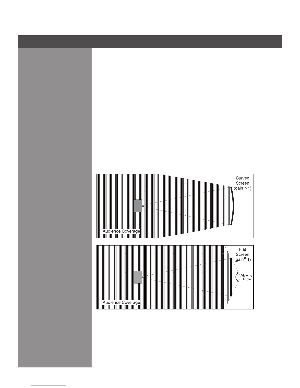
Optical screens take light from the projector and redirect it to increase the light intensity at the
front of the screen. This reduces it in other areas.Aviewing cone, similar to that of a curved front
screen installation is created. This type of screen is better suited for brightly lit rooms where the
audience is situated within the viewing cone.
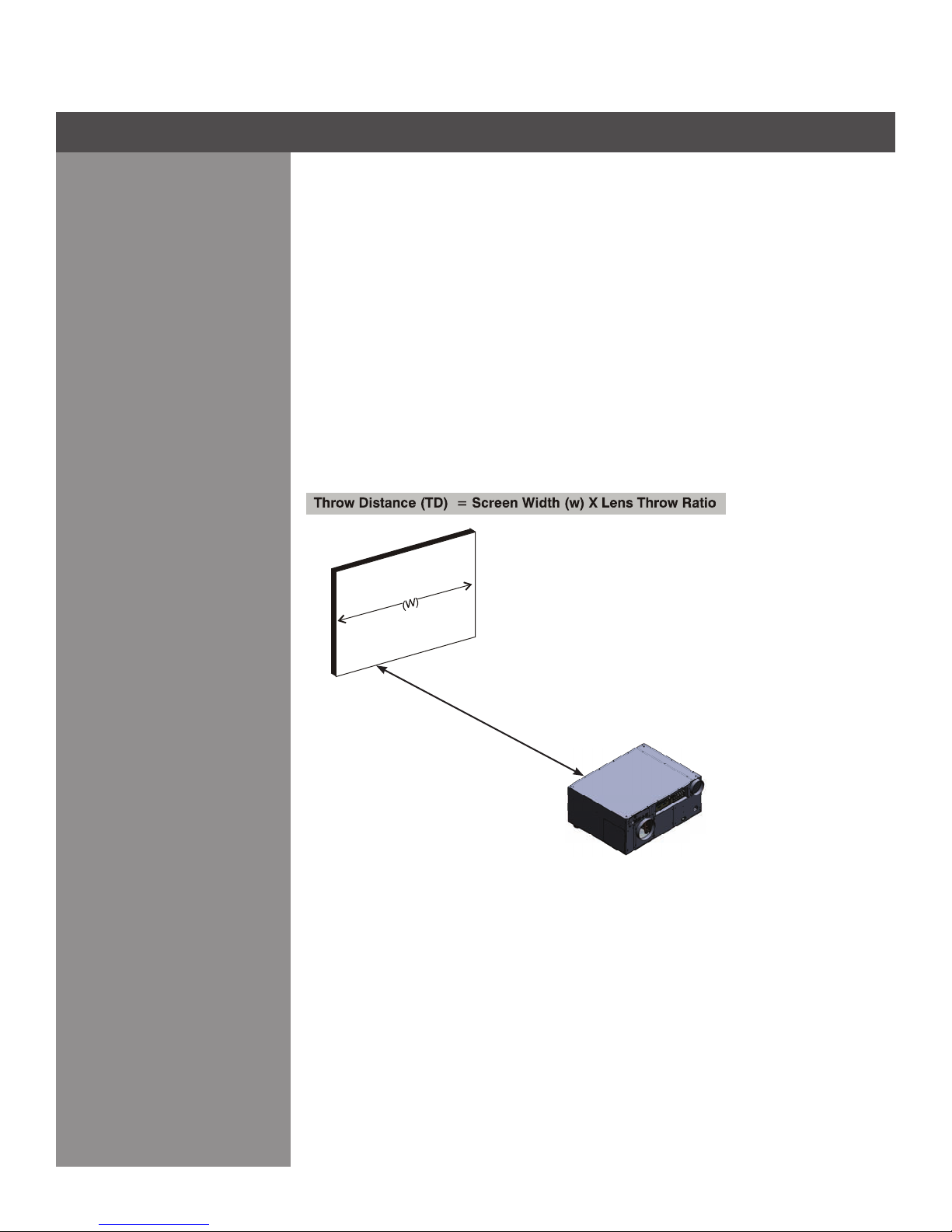
SCREEN SIZE
Choose a screen size, which is appropriate for your lens and application. The size of the room
andviewingdistancearethedeningfactors;aruleofthumbisthattheprimaryviewingdistance
be 1.5 x screen width.
Tollascreenwithanimage,theaspectratioofthescreenshouldbeequaltotheaspectratio
of the image (expressed as the ratio of its width to its height). Standard video from a VCR has
a 4:3 or 1.33:1 aspect ratio. For example, to display a VCR output with a 4:3 aspect ratio onto a
10-foot (3m) high screen, the width of the screen must be at least 13.3 feet (4m).
Section2►InstallationandSetup
Ambient Light
Other Considerations
The high brightness of this projector is well suited for locations where ambient lighting might be
considered less than ideal for projection. A typical room with ceiling lights and windows rarely
requires special attention. Contrast ratio in your images will be noticeably reduced if light directly
strikesthescreen,suchaswhenashaftoflightfromawindoworoodlightfallsontheimage.
Images may then appear washed out and less vibrant.
In general, avoid or eliminate light sources directed at the screen.
Other considerations and tips that can help improve your installation:
•Keeptheambienttemperatureconstantandbelow35°C(95°F).Keeptheprojectorawayfrom
heating and/or air conditioning vents. Changes in temperature may cause drifts in the projector
circuitry, which may affect performance.
•Keeptheprojectorawayfromdevicesthatradiateelectromagneticenergysuchasmotorsand
transformers.Commonsourcesoftheseincludeslideprojectors,speakers,powerampliers,
elevators, etc.
Choosethebestscreensizefortheapplication.Sincemoremagnicationreducesbrightness,
use a screen size appropriate for the venue but not larger than required. Installing a large screen
inasmallroomissimilartowatchingtelevisionatacloserange;toolargeascreencanoverpower
a room and interfere with the overall effect.Agood rule of thumb is to be no closer than 1.5 times
the width of the screen or a 23° viewing angle.

2-5
THROW DISTANCE
Throw distance is the distance measured from the screen to the front of the projector. This is
an important calculation in any projector installation as it determines whether or not you have
enough room to install your projector with a desired screen size and if your image will be of the
right size for your screen.
You can quickly estimate the throw distance by taking the horizontal width of the screen and
multiplying it by the lens throw ratio. The result of this calculation tells you "roughly" how far back
the projector should be positioned from the screen in order to project a focused image large
enoughtollthescreen.Forexample,usinga0.75:1lens,throwdistancewouldroughlybe0.75
x screen width.
IMPORTANT: Once you determine the type of lens and screen size you’re going to use, calculate
the precise throw distance using the formula located in Appendix C. Due to lens manufacturing
tolerances for lens focal length, actual throw distance can vary ±5% between lenses described
as having the same throw ratio.
Projector Position and
Mounting
Section2►InstallationandSetup
Iso - Rear Left View
Iso - Front Right View
Rear View
Top View
Side - Left View
Side - Right View
Iso - Rear Right View
Measure from the screen to the front of the projector

2-6
VERTICAL AND HORIZONTAL POSITION
The correct vertical and horizontal position of the projector in relation to the screen depends on
the lens type and the screen size. Ideally, the projector should be positioned perpendicular to the
screen. This way, the image will appear rectangular instead of keystoned (trapezoidal).
The vertical position of the image can be offset – that is moved above or below the optical axis
(lens center) by adjusting the fully motorized lens mount with the keypad. The amount of vertical
offset available depends directly on the lens installed in the projector and can be slightly limited
if horizontal offset has been applied. Vertical offset can also be expressed as the percent of half
the image height OR the number of pixels of shift from lens center. Refer to Figure 2.1 for some
illustrated examples of vertical offset.
Table 2.1 along with Figure 2.2 show the maximum vertical offset of a lens or alternatively, how
much of your projected image will appear above or below lens center if the maximum vertical
offset is applied using that lens.
Table 2.1 Lens Offsets
NOTES: 1) Offsets are subject to ±7% centering tolerance 2) % Offset = # pixels of offset / half
panel resolution x 100.
Lens Type
(All motorized lenses)
Offset Movement Max. Amount of Display
Above or Below Lens Center Max. Amount of Display
Right or Left of Lens Center
or or
HD Lenses 119% 42% 1183 pixels or 100% 1363 pixels or 71%
Section2►InstallationandSetup

2-7
Figure 2.1 Vertical Offset Examples
Section2►InstallationandSetup
Iso - Rear Left View
Iso - Front Right View
Rear View
Top View
Side - Left View
Side - Right View
Iso - Rear Left View
Iso - Front Right View
Rear View
Top View
Side - Left View
Side - Right View
Iso - Rear Left View
Iso - Front Right View
Rear View
Top View
Side - Left View
Side - Right View

2-8
Figure 2.2 Lens Vertical Offsets
Section2►InstallationandSetup
Iso - Rear Left View
Iso - Front Right View
Rear View
Top View
Side - Left View
Side - Right View
Iso - Rear Left View
Iso - Front Right View
Rear View
Top View
Side - Left View
Side - Right View
Iso - Rear Left View
Iso - Front Right View
Rear View
Top View
Side - Left View
Side - Right View
Iso - Rear Left View
Iso - Front Right View
Rear View
Top View
Side - Left View
Side - Right View

2-9
The horizontal position of the image can be offset – that is moved to the left or right of lens
center, by adjusting the fully motorized lens mount through software. The amount of horizontal
offset available depends on the lens installed and if the image has already been vertically offset.
Horizontal offset can also be expressed as the percent of half the image width – the number
of pixels of shift to one side of lens center. Refer to Figure 2.3 for some illustrated examples of
horizontal offset.
See also Table 2.1 along with Figure 2.4 which shows the maximum horizontal offset of a lens
or alternatively, how much of your projected image will appear to one side of lens center if the
maximum horizontal offset is applied using that lens.
Figure 2.3 Horizontal Offset Examples
Section2►InstallationandSetup
Iso - Rear Left View
Iso - Front Right View
Rear View
Top View
Side - Left View
Side - Right View
Iso - Rear Left View
Iso - Front Right View
Rear View
Top View
Side - Left View
Side - Right View

2-10
Figure 2.4 Lens Horizontal Offset Examples
Section2►InstallationandSetup
Iso - Rear Left View
Iso - Front Right View
Rear View
Top View
Side - Left View
Side - Right View
Iso - Rear Left View
Iso - Front Right View
Rear View
Top View
Side - Left View
Side - Right View
Iso - Rear Left View
Iso - Front Right View
Rear View
Top View
Side - Left View
Side - Right View
Iso - Rear Left View
Iso - Front Right View
Rear View
Top View
Side - Left View
Side - Right View

2-11
MOUNTING
There are several methods for mounting the projector. Depending on your chosen installation,
one method may be more suitable than another. In typical front and rear screen installations the
projector can be mounted to a secure and level surface, such as a table.
CEILING MOUNT — The projector can also be inverted and suspended from the ceiling using
a specially designed ceiling mount xture. This type of mounting is recommended for xed
installations and for those that want the projector out of sight or have a limited space for projector
and audience.
Use only the WOLF CINEMA approved ceiling mount kit designed for your projector.
Refer to the installation instructions and safety guidelines provided in the kit.
SPECIAL MOUNTING — The projector can be rotated (front-to-back) up to 360 degrees and
mounted without it affecting performance. However, the side-to-side tilt limit of the projector must
not exceed ±15 degrees. This tilt limit is required to ensure optimal performance of the lamp.
(Figure 2.5.)
ADJUSTING PROJECTOR HEIGHT
You can modify the height of the projector to remedy a slightly unlevel mounting surface by
adjusting the two feet threaded into the front bottom chassis. Turn each foot clock-wise or
counterclockwise until the project is level on all sides.
FOLDED OPTICS
In rear screen applications where space behind the projector is limited, a mirror may be used
to fold the optical path. The position of the projector and mirror must be accurately set—if
considering this type of installation call your dealer for assistance.
Section2►InstallationandSetup
Figure 2.5 Folded Optical Path
Iso - Rear Left View
Iso - Front Right View
Rear View
Top View
Side - Left View
Side - Right View

2-12
Sources connect to the Input Panel located at the back of the projector. See Figure 2.6.
The upper right corner (INPUT 1) typically accepts an RGB signal from an external analog RGB
source, or it can also be used for YPbPr signals or additional video sources. Just beside these
BNCs, the DVI-I connector (INPUT 2) accepts digital or analog display signals from a computer.
Connect analog composite video at INPUT 3 or S-Video at INPUT 4 from devices such as VCRs,
laser disc players or DVD players.
There are also several optional interfaces available for connecting other sources — these
interfaces slide into the remaining unused option slot, and can be done while the projector is
running.
Figure 2.6 Input Panel
NOTES: 1) See Section 6, Specications for details regarding compatible inputs. 2) Use high
quality shielded cables only for all connections.
INPUT 1 consists of ve BNCs (connectors) for linking to a variety of sources. The typical
connection would be to an RGB source such as a PC, Mac. This projector supports multiple sync
types with RGB signals: sync-on-green, composite sync, and separate H & V syncs.
NOTE: Depending on your source, you may need a custom adapter cable with BNC connectors
at the projector end and a different type of connector at the other (such as a 15-pin "D" connector
for some computer sources). Contact your dealer for details.
Connect the SYNCBNCinput(s)rst.Thenconnectthered,greenandbluesourceoutputsto
the RED, GREEN,and BLUE BNCs on the INPUT 1 panel. If the source uses sync-on-green,
only the red, green, and blue connections are required. If the source provides a composite
sync output, connect it to the SYNC input labeled HOR/COMP. If the source provides separate
horizontal and vertical sync outputs, connect horizontal sync to the SYNC input labeled HOR/
COMP and connect vertical sync to SYNC input labeled VERT. See Figure 2.7.
RGB Signals
RGB (BNC)
Section2►InstallationandSetup
2.3 Connecting Sources

2-13
Figure 2.7 Connecting RGB and Sync
NOTES: 1) If for some reason the projector fails to recognize a signal as an RGB signal, specify
this Color Space option within the PictureAdjustments menu. See 3.5 Adjusting the Image. 2) To
connect YPbPr signals–such as from DVDs or analog HDTV sources–to INPUT 1, use the red,
green and blue BNCs as described in YPbPr Signals (below).
Connect a YPbPr signal (component video) to INPUT 1 or INPUT 2 as shown in Figure 2.8.
NOTES: 1) If, for some reason, the projector fails to recognize a YPbPr signal, specify this Color
Space option within the Picture Adjustments menu. See 3.5, Adjusting the Image. 2) Do not
connect digital component signals (known as YCbCr) to INPUT 1. Install an appropriate optional
module in INPUT 5 or INPUT 6 for this.
YPbPr signals
(COMPONENT VIDEO)
Figure 2.8 Connecting YPbPr sources
Video
Source
From
Digital
Signals
from YPbPr
Source
Section2►InstallationandSetup

2-14
DVI Digital Video
INPUT 3 and INPUT 4 provide simultaneous connection of both a composite video source
(INPUT 3) and an S-Video source (INPUT 4). See Figure 2.9.
Use the DVI-I connector at INPUT 2 to connect either analog or digital video devices to the
projector. When connecting devices that transmit an analog video signal such as VCRs, laptops,
and PCs use the DVI cable provided with the projector. Plug the DVI-I (single link) connector
end to the projector and the 15-pin VGA connector to the device.
Use a cable with DVI-I connectors at both ends to connect devices that transmit digital and
analog video signals such as high-quality DVD players, satellite receiver and digital cable TVs.
NOTES: 1) To ensure true digital output from devices that transmit digital signals, connect to
the DVI-I connector. 2) DVI loop through is not available unless you have the optional DVI Input
Module installed at INPUT 5 or INPUT 6.
Optionalmodules allowyou toincrease yourtotal numberof inputsand/or accommodatedifferent
signal types, whether analog or digital. Install in the areas labeled INPUT 5 or INPUT 6. Options
include:
Serial Digital Input Module - HD (SDI)•
DVI Input Module• (standard on XXXX HD models)
Dual SD/HD-SDI Module• (standard on XXXX HD models)
NOTE: See Appendix E – Optional Input Modules for a brief description of each interface.
Figure 2.9 Connecting Composite or S-Video sources
Composite and S-Video
Optional Inputs
Section2►InstallationandSetup

2-15
As an alternative to the projector’s keypad or remote, you may wish to communicate with the
projector using a PC or other controller. Such a device sends commands and receives feedback
via serial links (RS232 and RS422), Ethernet or GPIO communications to the projector, all
described below.
As desired, direct the projector’s IR remote keypad towards the display screen or the projector’s
IR sensors. Alternatively, connect a wired (tethered) version of the remote to the 3.5mm mini-
stereo jack labeled as REMOTE on the projector’s input panel. Note that response to a Wired
Keypad must also be enabled in the Communications menu — see 3.6, Adjusting System
Parameters and Advanced Controls for more information.
Therearetwo types ofserial ports availableon the projector:RS232 and RS422.You can connect
a device with a serial interface, such as a computer to either of these connectors (not both) and
controltheprojectorremotelybyenteringspecicserialcommunicationcommands.
CONNECTING RS-232
The two nine-pin DIN connectors labeled RS232 IN and RS232 OUT on the input panel are
dedicated to serial communication (see Figure 2.10). Using the appropriate serial communication
cables (see Appendix B) connect the controlling source, such as a personal computer to the
RS232 IN connector. Then set the baud rate to match that of the computer. Refer to Section 3
for details on changing the projector’s baud rate.
Remote Keypads
Serial Port Connections
Figure 2.10 Connecting RS-232
From WC-Pro Processor
Section2►InstallationandSetup
2.4 Connecting
Communications

2-16
Figure 2.11 Connecting RS-422
ETHERNET COMMUNICATIONS
To add the projector to an existing Ethernet network with other equipment such as controllers
and other projectors, connect standard CAT5 Ethernet cable between your Ethernet controller (or
hub) and the Ethernet port on the side of the projector.
Upon connection to an Ethernet network, the projector’s factory default IP address of 0.0.0.0.0
will automatically enable the DHCP function (if available on the network) to assign a new IP
address that is valid and unique for that network. Or, if there is no DHCP function available on
thenetwork(orifaspecicstaticIPaddressfortheprojectorispreferredorrequired),youcan
set the address in the Ethernet Settings menu or via an ASCII serial command.
Regardless of how it is assigned, once a projector has a valid and unique address it will respond
to commands sent to this address. To determine the projector’s current IP address, consult the
Information or Communications menus.
Refer to Section 3 for further information about setting up and using a projector connected via
Ethernet.
Ethernet Communications
Connect a RS422 device only.
Section2►InstallationandSetup
CONNECTING RS-422
If you wish to control the projector with a computer and or other controlling device with RS-422
capability, connect a RS-422 serial communication cable between the computer and the RS-422
port on the projector (see Figure 2.11). RS-422 is better suited for serial communication over
long distances then is RS-232 communication.
Use the RS-422 port only if your device had RS-422 capability – always consult the
literature provided with your equipment before connecting. Connecting to the RS-422
port with incompatible equipment could damage your projector.
This manual suits for next models
5
Table of contents
Other Wolf cinema Projector manuals
Popular Projector manuals by other brands

Panasonic
Panasonic PT-AE8000U operating instructions

Astral Pool
Astral Pool 33709 MINI” LIGHT FOR SPAS PROJECTEUR “MINI” POUR SPAS PROYECTOR “MINI” PARA SPAS FARO “MINI” PER SPA MIN

Elmo
Elmo Boxi MP-350 quick start guide

Elmo
Elmo HP-L1102 instruction manual

Dream Vision
Dream Vision T9006000 Assembly and calibration

Evo-lite
Evo-lite ArchiTECH 150 user manual