manuals.online logo
Brands
  1. Home
  2. •
  3. Brands
  4. •
  5. Wolf
  6. •
  7. Freezer
  8. •
  9. Wolf Sub-Zero BI Series User manual

Wolf Sub-Zero BI Series User manual

This manual suits for next models

2

Popular Freezer manuals by other brands

LG freezer owner's manual

LG

LG freezer owner's manual

Whirlpool EH221FXRQ00 parts list

Whirlpool

Whirlpool EH221FXRQ00 parts list

Ryobi P3370 Operator's manual

Ryobi

Ryobi P3370 Operator's manual

Iceking IK2022WE Installation and operating manual

Iceking

Iceking IK2022WE Installation and operating manual

SEVERIN DT 8760 Instructions for use

SEVERIN

SEVERIN DT 8760 Instructions for use

mykin MCF146W quick start guide

mykin

mykin MCF146W quick start guide

Haier HCM070EA user manual

Haier

Haier HCM070EA user manual

Haier DW-86L486 After-sales Service Manual

Haier

Haier DW-86L486 After-sales Service Manual

DAEWOO ELECTRONICS DAEMA DFZ-685CG user manual

DAEWOO ELECTRONICS

DAEWOO ELECTRONICS DAEMA DFZ-685CG user manual

Siemens GU..D SERIES Instructions for use

Siemens

Siemens GU..D SERIES Instructions for use

Omcan FR-CN-0155 instruction manual

Omcan

Omcan FR-CN-0155 instruction manual

Electrolux ARCTIS G 8 60 50-6I user manual

Electrolux

Electrolux ARCTIS G 8 60 50-6I user manual

Frigidaire FV 1246 H Instruction book

Frigidaire

Frigidaire FV 1246 H Instruction book

Electrolux EUF2042AOX user manual

Electrolux

Electrolux EUF2042AOX user manual

Dometic CoolFreeze CFX95DZ operating manual

Dometic

Dometic CoolFreeze CFX95DZ operating manual

Electrolux EUF7000W1 user manual

Electrolux

Electrolux EUF7000W1 user manual

SAF PRESTOTIG 200AC/DC Installation and instruction manual

SAF

SAF PRESTOTIG 200AC/DC Installation and instruction manual

Zanussi ZFT11407WA user manual

Zanussi

Zanussi ZFT11407WA user manual

manuals.online logo
manuals.online logoBrands
  • About & Mission
  • Contact us
  • Privacy Policy
  • Terms and Conditions

Copyright 2025 Manuals.Online. All Rights Reserved.

BI-36F 111
subzero.com 800.222.7820
BI
Service Manual
Page 2
6-32
7040317 - Revision A - September, 2015
Component Removal Built-In (BI) Series
Built-In (BI) Series (SWS #4380000)
(SWS #4380000)
Kickplate
To remove a kickplate, extract the screws from the left
and right corners of the kickplate, then pull the kickplate
forward. (See Figure 6-76).
Dual Installation Kickplate
A dual installation kickplate assembly is held in place
with magnets at each end and one screw at top center.
To remove the dual installation kickplate, the screw at
top center must be extracted before pulling the dual
installation kickplate forward (See Figure 6-77).
Drain Pan
The drain pan slides in from the front of unit on two side
brackets. A locating feature was built into the drain pan
in the form of detentes at the bottom front that drop into
notches at the front of the side brackets.
To remove the drain pan (See Figure 6-78):
1. Remove kickplate.
2. Push front of drain pan up slightly, then pull for-
ward.
Figure 6-76. Kickplate Removal
Figure 6-78. Drain Pan Removal
Drain Pan
Figure 6-77. Dual Installation Kickplate
Dual Installation Kickplate
Screw
Kickplate
Screw
Model BI-36F Exterior Cosmetic / Mechanical Components
Page 3
6-33 7040317 - Revision A - September, 2015
Built-In (BI) Series
Built-In (BI) Series (SWS #4380000)
(SWS #4380000) Component Removal
Water Valve Assembly
NOTE: Before attempting to remove an isolation &/or
water valve assembly, switch the water supply to the
unit off.
To remove a valve assembly (See Figure 6-79):
1. Extract valve assembly mounting screws and pull
valve forward.
2. Disconnect AC (and DC if applicable) electrical
leads.
NOTE: It may be necessary to cut a cable tie that
is securing the AC electrical leads to the valve
assembly.
3. Disconnect inlet and outlet water tubes from valve
by pushing the collar around the tubes toward the
valve, while pulling the tubes away from the valve.
Grille Assembly
The grille assembly is attached at the top of the unit
with screws passing through the grille’s side frames into
grille brackets.
To remove a grille assembly (See Figure 6-80):
1. Lift open the front of the grille assembly to access
the mounting screws.
2. With a T-20, 6-lobe Torx type bit, extract the two
front grille mounting screws, then loosen but do not
remove the two rear mounting screws.
3. pull the grille assembly forward, off of the unit.
NOTE: When reinstalling the grille assembly, line up
the notches at back of grille side frames with the rear
mounting screws, then push the grille assembly back.
Water Filter
The water filter and manifold are located at the right-
hand top side of the unit behind grille assembly.
To remove the filter, first lift open the front of the grille
assembly, then (See Figure 6-81):
1. Rotate filter counterclockwise to remove it (clock-
wise to install it).
2. Then pull cartridge out of the manifold.
NOTE: After a filter cartridge has been replaced, the
reset button behind the unit grille must be pressed for
five (5) seconds to clear the filter icon from the LCD
and reset the water filter timer.
Figure 6-79. Water Valve Removal
DC Connection
AC Connection
Collar
Inlet Tube
Outlet Tube
Figure 6-80 Grille Assembly Removal
Grille Mounting Screws
Grille Assembly
Grille Bracket
Grille Bracket
Figure 6-81. Filter Removal
Water Filter
Page 4
6-34
7040317 - Revision A - September, 2015
Component Removal Built-In (BI) Series
Built-In (BI) Series (SWS #4380000)
(SWS #4380000)
Water Filter Manifold/Valve
The water filter and manifold are located at the right-
hand top side of the unit behind grille assembly.
NOTE: Before attempting to remove the water filter
manifold, switch the water supply to the unit off.
To remove the water filter manifold, first remove the
water filter, then (See Figure 6-82):
1. Extract mounting screws from mounting bracket.
2. Disconnect wire leads from manifold.
3. Disconnect water tubes from manifold.
4. Extract mounting screws from manifold mounting
bracket and pull manifold forward.
Door Switch
The door switch is located at the top rear of the top
cabinet frame, with the switch’s actuator protruding
through a hole in the front of the frame. A series of tabs
and pegs hold the door switch in place.
To remove a door switch, first open the grill, then (See
Figure 6-83):
1. Disconnect the switch electrical leads using a nee-
dle-nose pliers to pull the electrical lead housings
away from the switch.
2. Use a small flat-blade screwdriver to pry the front
retaining tab at each side of the switch back while
lifting that side of the switch up. Repeat this step
on each side of the switch.
3. Pull switch back and lift off of the top cabinet frame
Top Cabinet Trim
The top cabinet trim sits below the grille assembly.
Screws pass through open ended slots in the trim to
secure it to the top cabinet frame.
To remove the top cabinet trim first open the grill then,
(See Figure 6-84):
1. Use a T-15, 6-lobe Torx type bit, to loosen, but not
remove, the trim mounting screws.
2. Pull the trim forward. off of the unit.
Figure 6-82. Filter Manifold (Rear View)
Electrical
Connection
Water
Connection
Water
Connection
Screws
Manifold/Valve
Figure 6-83. Door Switch Removal
Figure 6-84. Top Cabinet Trim Removal
Retaining Tab
Switch
Cabinet Frame
Trim Mounting Screws
Top Cabinet Trim
Page 5
6-35 7040317 - Revision A - September, 2015
Built-In (BI) Series
Built-In (BI) Series (SWS #4380000)
(SWS #4380000) Component Removal
Framed / Overlay Door Handle / Handle-Side Trim
The door handle on framed units and the handle-side
trim on overlay units is attached to the door with
screws. These screws are covered by a screw cover.
To remove a handle of handle-side trim, open the door
then:
1. At the top of the door, insert a flat blade screwdriver
into the channel of the screw cover and push the
cover back, disengaging it from the handle or trim
(See Figure 6-85).
2. With a T-20, 6-lobe Torx type bit, extract the handle-
side trim mounting screws and pull the trim from the
door (See Figure 6-86).
Stainless Steel Door Handle Assembly
A screw inserted through the stainless steel handle
standoffs into the handle secures the handle to the
standoffs. The standoffs are then slides over threaded
studs that are attached to the door shell. A socket head
set-screw inserted through the side of the standoff
secures the standoff to the stud.
To remove a stainless steel handle assembly (See
Figure 6-87):
1. Use a 3/32” Allen-wrench to loosen the set-screw in
each handle standoff.
2. Pull handle assembly off of the threaded studs.
DOOR
SCREW COVER
HANDLE-SIDE TRIM
Figure 6-85. Screw Cover Removal
HANDLE-SIDE TRIM
DOOR
Figure 6-86. Handle / Handle-Side Trim Removal
Figure 6-87. Cut-away View of SS Handle Assembly
Handle Mount
Screw Threaded Stud
Set-Screw
Handle Standoff
Handle
Page 6
6-36
7040317 - Revision A - September, 2015
Component Removal Built-In (BI) Series
Built-In (BI) Series (SWS #4380000)
(SWS #4380000)
Top Door Hinge Assembly
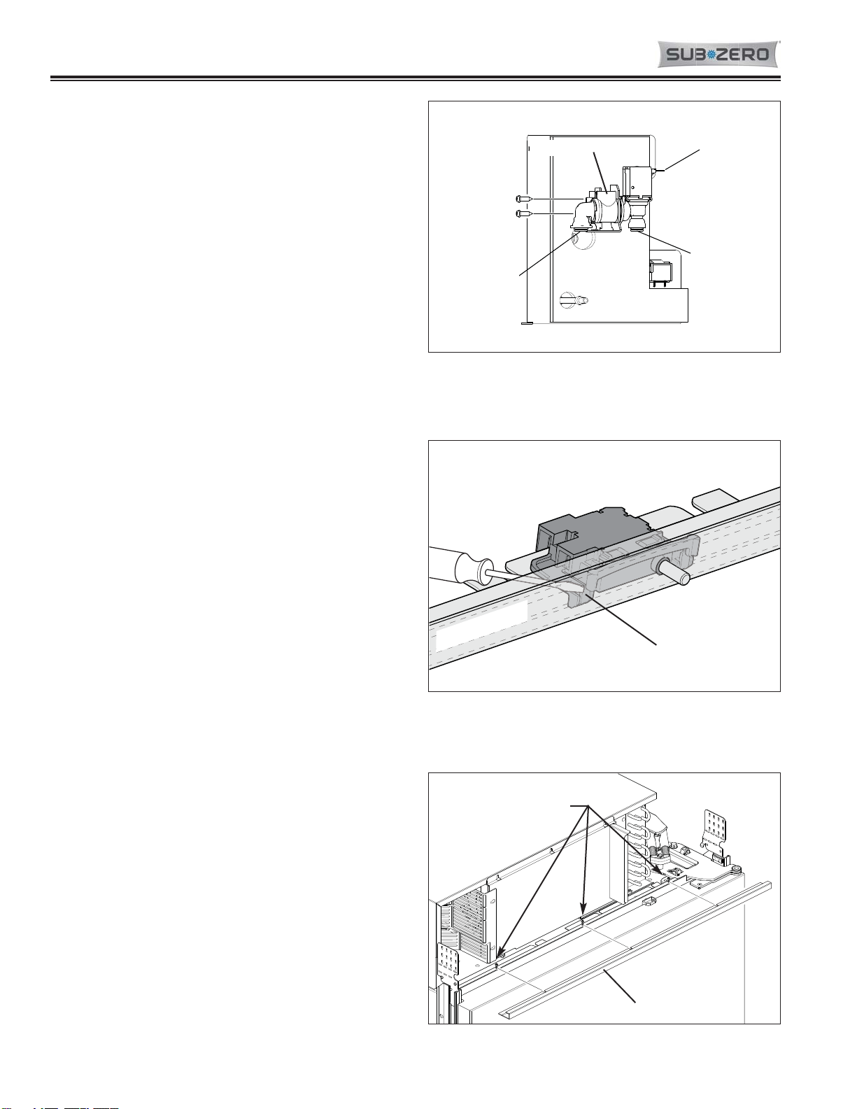
The top hinge assembly is secured to the unit with bolts
that pass down through the cabinet hinge plate into
threaded inserts. Screws passing down through the
door hinge secure the hinge assembly to the door.
NOTE: A special tool package is available to assist in
removing a top hinge assembly. This tool package is
provided with replacement hinge and door assemblies.
If needed, order part #7011097. The directions below
were written to be used with this tool package.
To remove a top hinge assembly, the grille assembly
and top cabinet trim must be removed first. If removing
a right-hand door, remove the water filter cartridge at
this time, then:
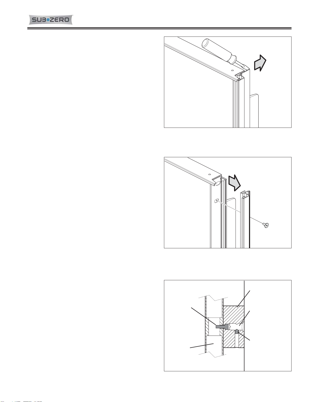
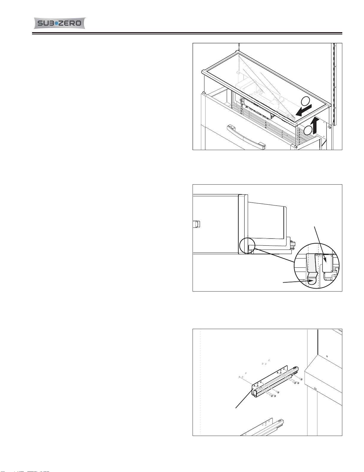
1. With the door open, use a 5/32” Allen wrench or bit
to extract the top door hinge mounting screw near-
est to the hinge pivot point (See Figure 6-88).
2. Use a 1/8” Allen wrench or bit to replace the screw
just removed with the 1/4-20X1/2” setscrew, includ-
ed in the tool package, inserting the setscrew down
until its top is flush with the top surface of the door
hinge (See Figure 6-88).
NOTE: If the setscrew is not inserted far enough it
will damage the hinge plate when closing the door;
if it is inserted too far it will not hold the door hinge
in the correct position when closing the door.
3. Extract the inner door hinge mounting screws, leav-
ing the outermost screw in place (See Figure 6-88).
4. insert the hinge spacer, included in the special tool
package, between the door closer guide and the
back of the door closer track, then close the door
(See Figure 6-88).
NOTE: This spacer will keep the door closer mech-
anism at the proper spacing to facilitate hinge
assembly removal and reinstallation.
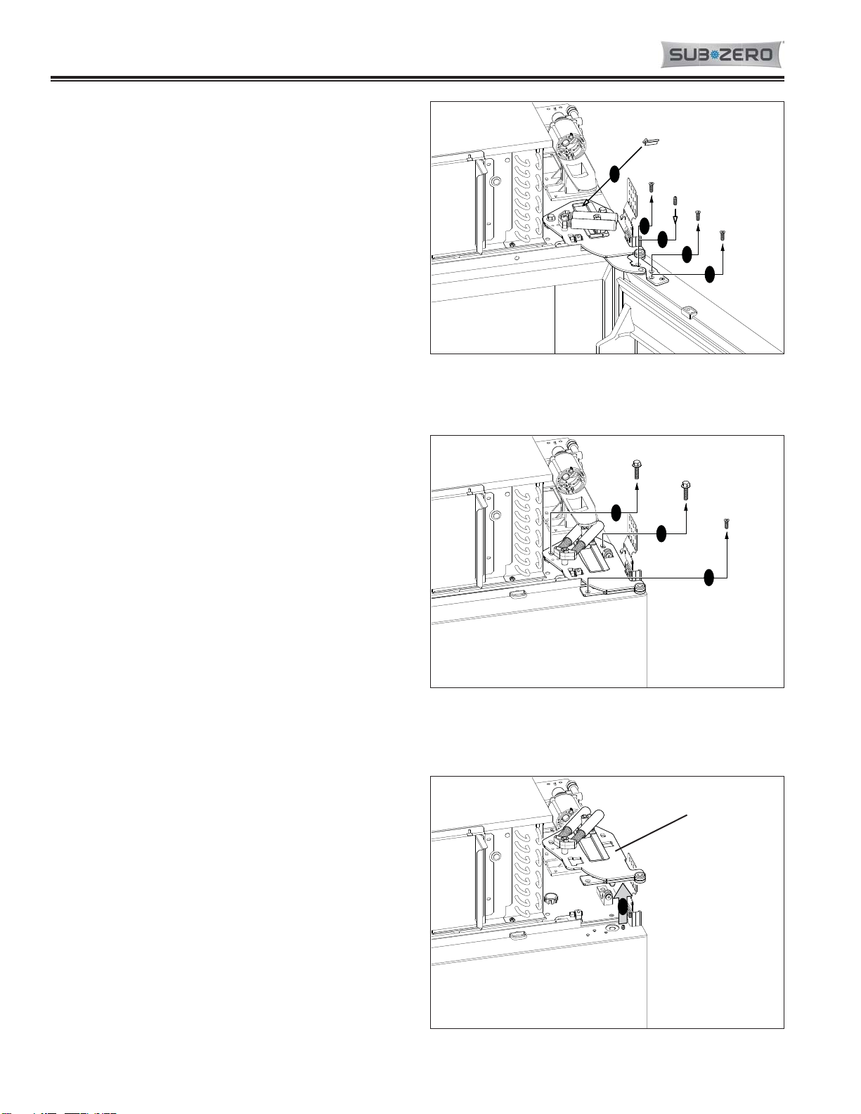
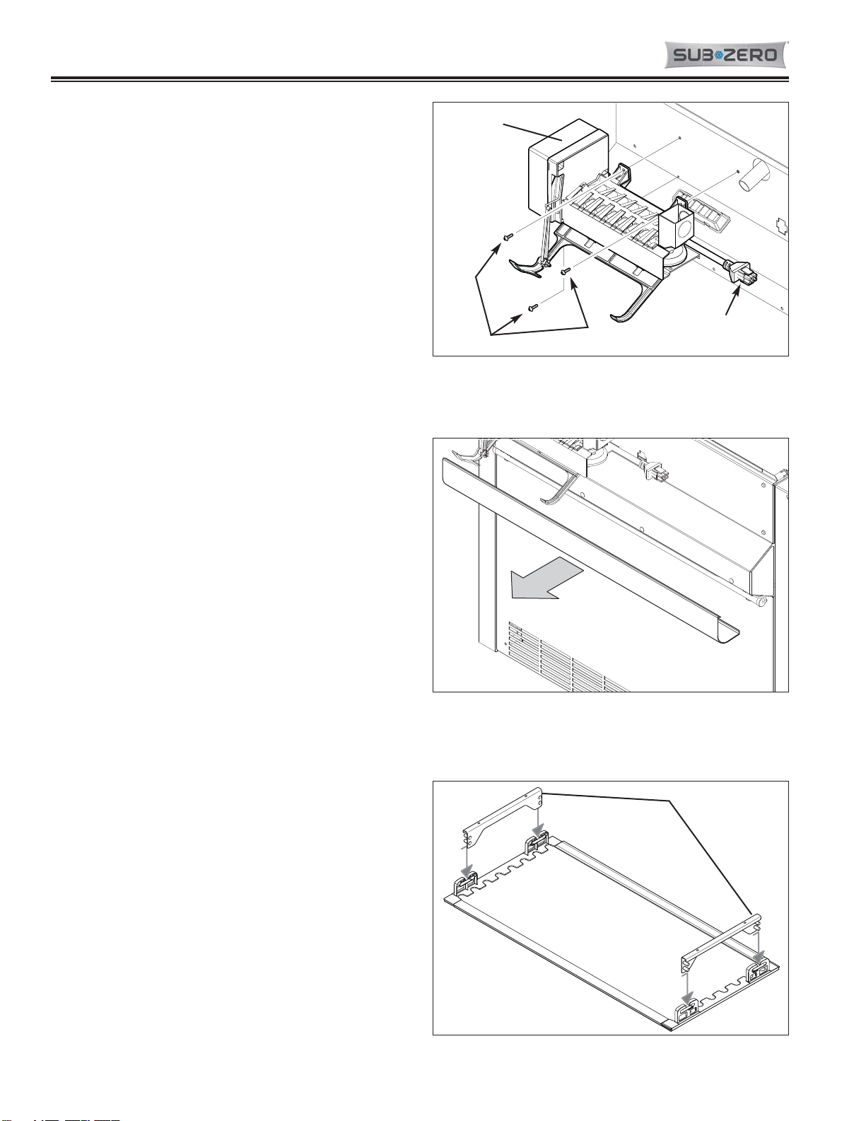
5. With the door closed, use a socket wrench with an
extension and a ½” socket to extract the cabinet
hinge mounting bolts (See Figure 6-89).
6. Extract the outermost door hinge mounting screw
(See Figure 6-89).
7. Lift the hinge assembly up off of the top of the unit,
allowing the door to shift toward the handle side
and come to rest against the main frame (See
Figure 6-90).
NOTE: It may be necessary to use a flat blade
screwdriver to pry the post at the end of the door
closer arm up out of the hole in the top of the door
assembly.
3
2
1
3
4
Figure 6-88. Top Door Hinge Screw Removal,
Setscrew Installation and Spacer Installation
5
5
6
Figure 6-89. Cabinet Hinge Bolt Removal and Door
Hinge Screw Removal
7
Figure 6-90. Top Door Hinge Assy Removal
Hinge Assy
Page 7
6-37 7040317 - Revision A - September, 2015
Built-In (BI) Series
Built-In (BI) Series (SWS #4380000)
(SWS #4380000) Component Removal
Door Assembly
The door assembly is secured to the top and bottom
door hinges with screws. The post of the bottom door
hinge fits down into a bearing in the bottom cabinet
hinge assembly’s door adjuster.
To remove a door assembly, the top hinge assembly
must be removed first. Then, with one hand at each
side of the door, open the door forty-five to ninety
degrees and lift it off of the bottom cabinet hinge
assembly. (See Figure 6-91)
Bottom Cabinet Hinge Assembly
The bottom cabinet hinge assembly is attached to the
bottom of the unit with bolts.
To remove the bottom cabinet hinge assembly, first
remove the top hinge assembly and the door. Then,
using a 1/2” wrench or socket, extract the cabinet hinge
mounting bolts and pull the hinge assembly from the
unit. (See Figure 6-92)
Figure 6-91. Door Assembly Removal
Door Assembly
Figure 6-92. Cabinet Hinge Assembly Removal
Bottom Cabinet
Hinge Assembly
Bottom Cabinet
Hinge Assembly
Bolts
Page 8
6-38
7040317 - Revision A - September, 2015
Component Removal Built-In (BI) Series
Built-In (BI) Series (SWS #4380000)
(SWS #4380000)
Model BI-36F Interior Cosmetic / Mechanical Components
Door Gasket
A dart at the back of the door gasket fits into metal
channels attached to the inside perimeter of the door.
To remove a door gasket, starting at one corner, pull
the gasket dart from the metal channels. (See Figure
6-93).
Adjustable Door Shelves
Removal and adjustment of the door shelves is
achieved by sliding the grooves in the shelving end-
caps over the molded retaining ribs of the door liner.
Lift out and up to remove, push in and down to install.
(See Figure 6-94).
Cantilever Shelf Assembly
To adjust and/or remove a freezer cantilever wire shelf
assembly (See Figure 6-95):
1. Lift front of shelf up slightly.
2. Lift back of shelf up to disengage the shelf ladder
hooks from the shelf ladders.
3. Pull shelf forward and out of the shelf ladders.
Figure 6-93. Door Gasket Removal
Metal Channels
Gasket
Figure 6-94. Adjustable Door Shelf
Door Shelf
2
1
3
Figure 6-95. Cantilever Shelf Removal
Page 9
6-39 7040317 - Revision A - September, 2015
Built-In (BI) Series
Built-In (BI) Series (SWS #4380000)
(SWS #4380000) Component Removal
Fixed Glass Shelf Assembly
The freezer fixed glass shelf rests upon shelf standoffs
that are mounted to the freezer side walls.
To remove the freezer fixed glass shelf (See Figure 6-
96):
1. Lift shelf straight up off of the standoffs.
2. Pull shelf forward, out of compartment.
Ice Bin
To remove the ice bin, open the top freezer basket and
lift the ice bin out of the basket (Not Shown)
Freezer Basket Assembly
To remove a freezer basket assembly (See Figure 6-
97):
1. Pull basket open until it stops.
2. Remove basket contents.
3. Simultaneously depress both locking tabs under
bottom front corners of basket assembly and lift up
on basket front.
4. With basket front straight up, place bottom corner of
basket on hinge side into gap between door and
face frame, then pivot other end of basket assembly
out of the compartment.
Freezer Basket Slide
The basket slides are secured with screws to the com-
partment side walls.
To remove a basket slide, first remove the basket
assembly, then extract the slide’s mounting screws and
pull the slide from the side wall. (See Figure 6-98)
Figure 6-97. Freezer Basket Assembly Removal
1
2
Figure 6-96. Freezer Glass Shelf Removal
Freezer
Basket
Assembly
Locking Tab
Basket
Slide
Figure 6-98. Freezer Basket Slide Removal
Basket Slide
Page 10
6-40
7040317 - Revision A - September, 2015
Component Removal Built-In (BI) Series
Built-In (BI) Series (SWS #4380000)
(SWS #4380000)
Icemaker Assembly
The icemaker assembly is attached to the left side of
the middle duct assembly with screws.
To remove ice maker, first remove the fixed glass shelf
assembly and the upper freezer basket assembly, then
(See Figure 6-99):
1. Use a small flat-blade screwdriver to pry latches of
male electrical connector from tabs of female con-
nector, then disconnect icemaker electrical leads.
2. Extract icemaker mounting screws (two at top, one
at bottom), then pull icemaker assembly from com-
partment.
Lower Light Diffuser
The lower light diffuser behind the upper freezer basket
assembly is a flexible plastic material and is held in
place with flanges at the top and bottom of the diffuser
fitting over metal flanges that Are attached to the lower
duct assembly.
To remove the light diffuser, first remove the fixed glass
shelf and upper freezer basket, then (See Figure 6-
100):
1. At each end of diffuser, pull it down to disengage
diffuser bottom flange from behind lower metal
flange.
2. At each end of diffuser, pull it forward to disengage
diffuser top flange from behind upper metal flange
and remove diffuser from the compartment.
Upper Light Diffuser Assembly
The upper light diffuser assembly, located at the top of
the freezer compartment, is held in place by inverted T-
shaped slots at its sides fitting over pegs on the light
diffuser brackets.
To remove the upper light diffuser assembly (See
Figure 6-101):
1. Push diffuser toward rear of unit until center of
inverted T-shaped slots line up with diffuser bracket
pegs.
2. Lower diffuser down and pull it from the compart-
ment.
NOTE: When reinstalling the light diffuser, be sure to
pull it forward fully so that the tabs inside the inverted T-
shaped slots engage the pegs in the diffuser brackets.
Failure to do so will allow the diffuser to fall out easily.
Figure 6-101. Upper Light Diffuser Removal
Diffuser Brackets
Light Diffuser
(Top View)
Figure 6-99. Icemaker Assembly Removal
Electrical
Connection
Screws
Icemaker
Assembly
Figure 6-100. Lower Light Diffuser Removal
Lower Light Diffuser