YAESU
FC-700
ANTENNA
COUPLER
GENERAL
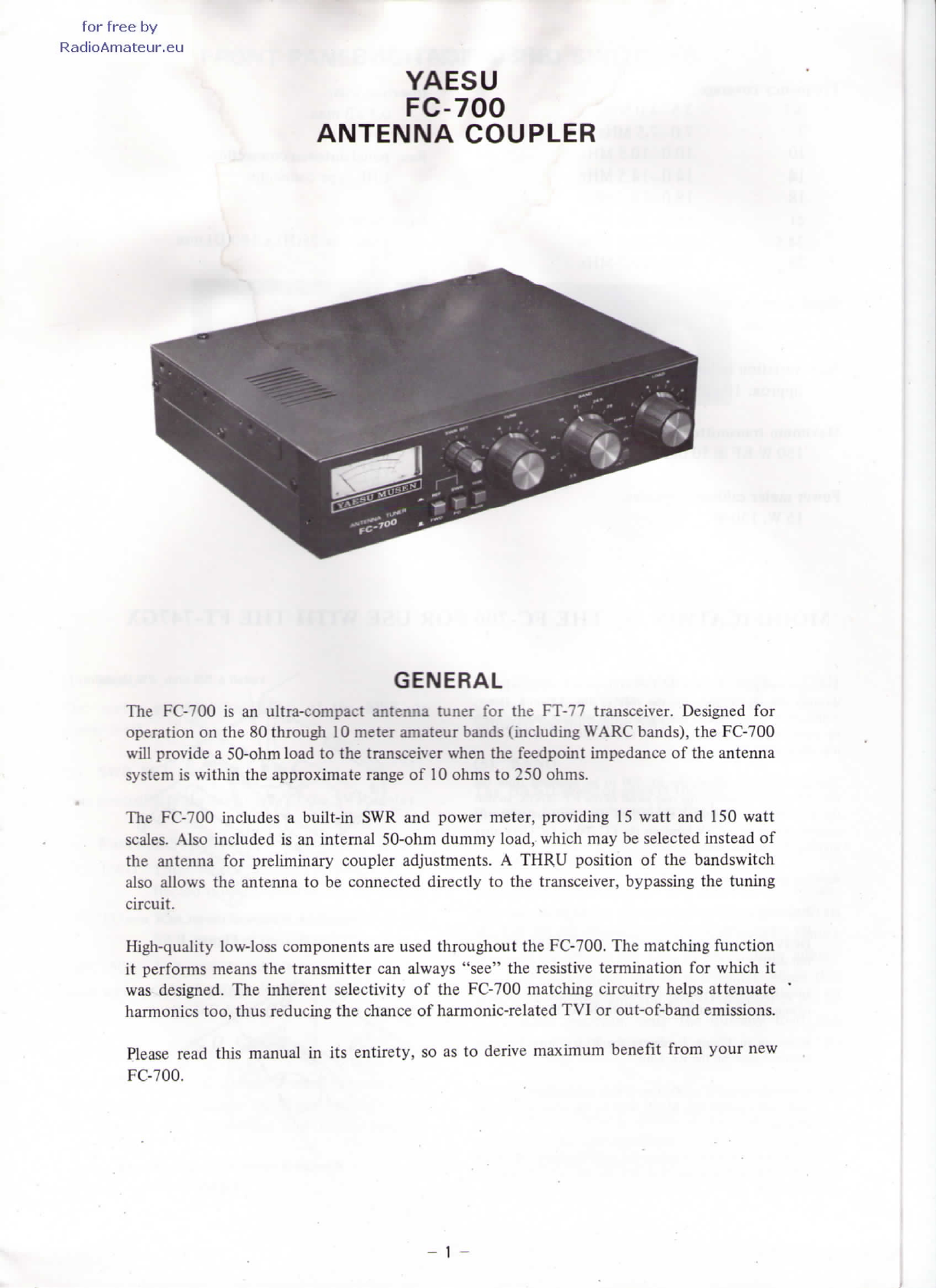
The
FC-700
isan
ultra-compactantennatuner
for
thé
FT-77
transceiver.Designed
for
opération
on
thé
80
through
10
meter
amateurbands
(including
WARC
bands),
thé
FC-700
will
provide
a
50-ohmload
to
thé
transceiverwhen
thé
feedpointimpédance
of
thé
antenna
System
is
within
thé
approximaterange
of10
ohms
to250
ohms.
The
FC-700
includes
a
built-in
SWRand
powermeter,providing
15
watt
and150
watt
scales.
Alsoincluded
isan
internai50-ohmdummyload,which
maybe
selectedinstead
of
thé
antenna
for
preliminarycoupleradjustments.
A
THRU
position
of
thé
bandswitch
also
allows
thé
antenna
tobe
connecteddirectly
to
thé
transceiver,
bypassing
thé
tuning
circuit.
High-quality
low-loss
components
are
used
throughout
thé
FC-700.
The
matchingfunction
it
performs
means
thé
transmitter
can
always
"see"
thé
résistive
termination
for
which
it
was
designed.
The
inhérentselectivity
of
thé
FC-700
matchingcircuitry
helps
attenuate
harmonies
too,
thus
reducing
thé
chance
of
harmonic-related
TVI
or
out-of-bandémissions.
Please
readthismanual
inits
entirety,
soasto
dérivemaximum
benefit
from
your
new
FC-700.