Zero Zone RVZC30 User manual


RVZC30(andBB/T/TBB/WA),RVZP30(andBB/T/TBB/WA),RVC24
2
0407

RVZC30(andBB/T/TBB/WA),RVZP30(andBB/T/TBB/WA),RVC24
3
0407
TABLE OF CONTENTS
INTRODUCTION ...................................................................4
DELIVERYINSPECTION ......................................................4
PACKAGING ........................................................................4
LOCATION ............................................................................4
Figure 1: Case label information...................................... 5
INSTALLATION .....................................................................6
Leveling ........................................................................... 6
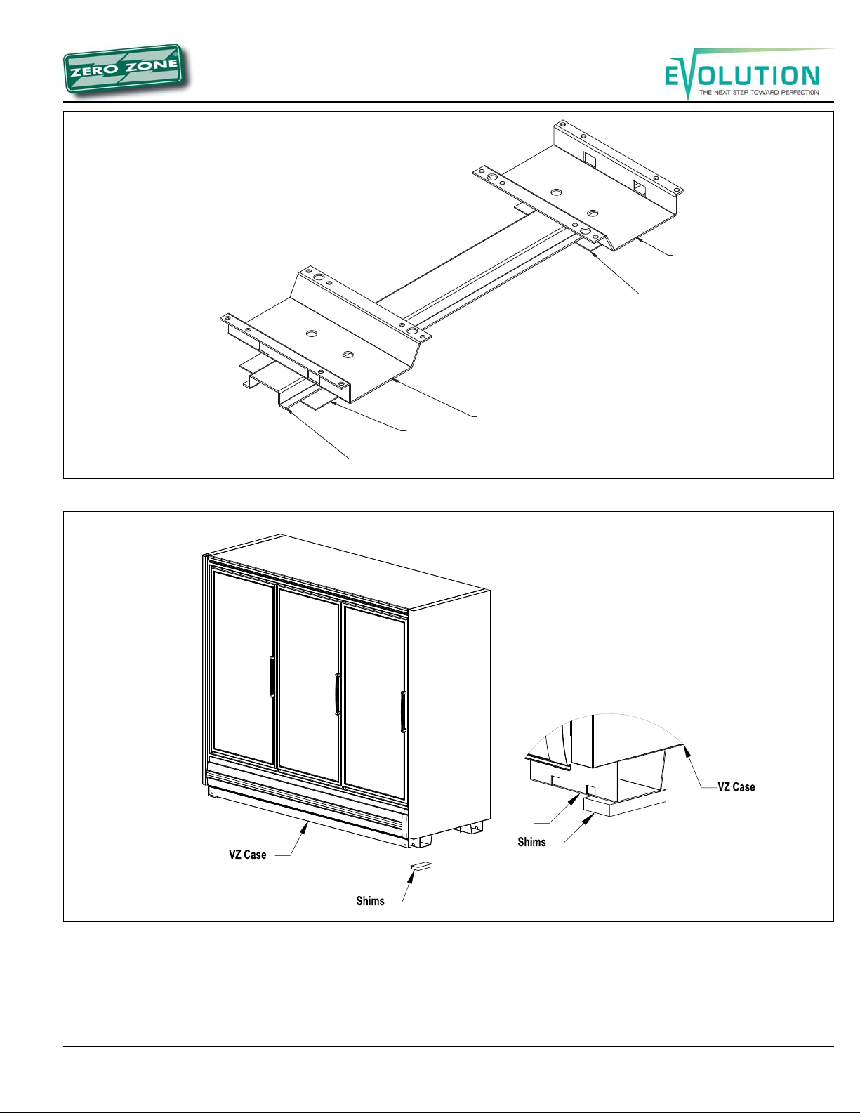
Figure 2: Leveling cases prior to joining .......................... 6
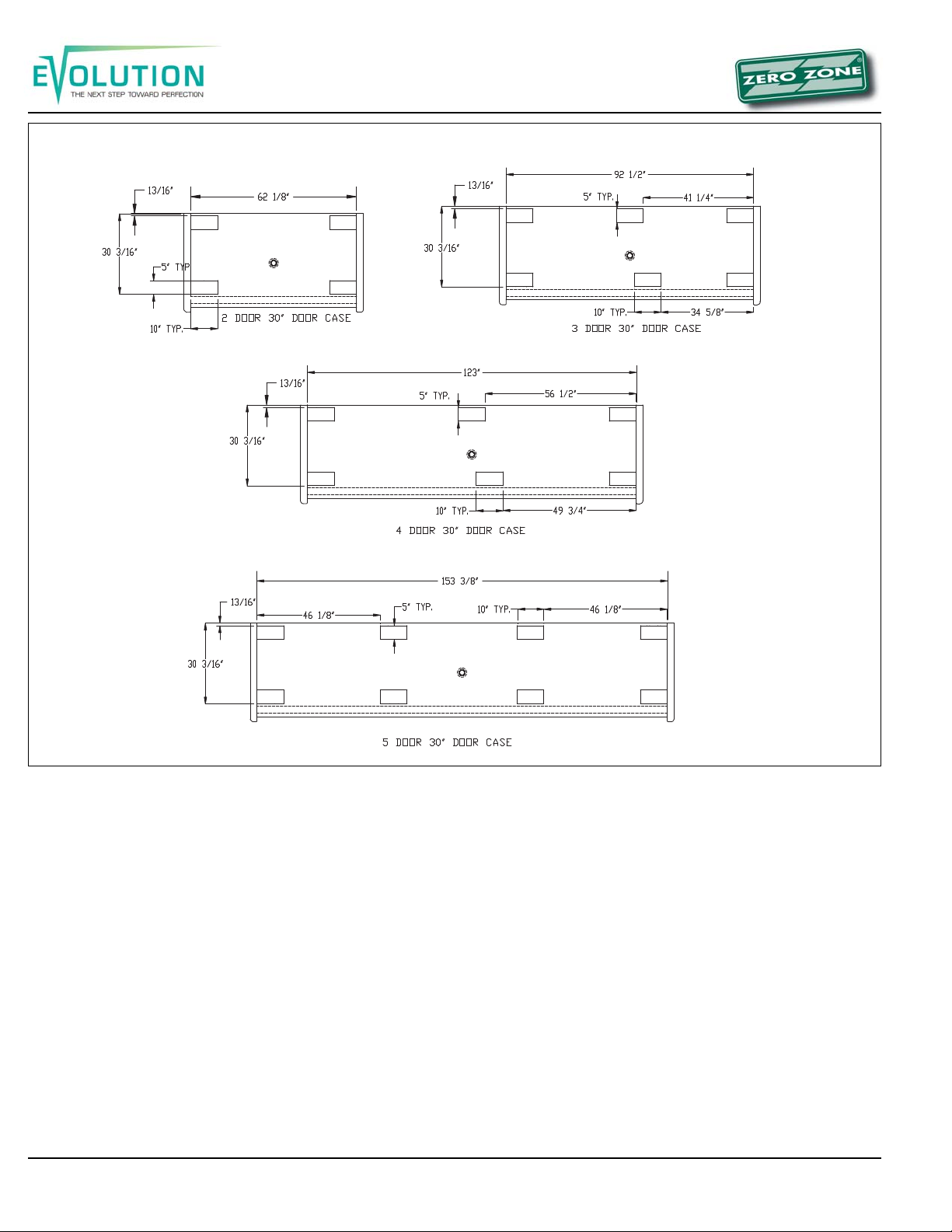
Figure 3: Typical hat channel locations............................ 7
Figure 4: Shims under bases and case ........................... 7
Figure 5A:All base locations ........................................... 8
Figure 5B:All base locations ........................................... 9
Figure 5C:All base locations ......................................... 10
CASEMOVEMENT ............................................................ 11
Figure6:Removingwoodplanks ................................... 12
Figure 7: Wood block inside base................................. 12
Figure8:Expandable base............................................ 12
LINEUPASSEMBLY ..........................................................13
Figure 9: Caulking cases to be joined ........................... 13
Figure 10: T-strips ......................................................... 13
Figure 11: Required sealing for
NSFapprovedinstallations .......................................... 14
DRAINLINE ........................................................................14
Figure 12: Trap support................................................. 14
BUMPERAND KICKPLATE ........................................... 15
InstallingEndKick Plate ................................................ 15
InstallingBumper ........................................................... 15
Figure 13: Other style bumpers ..................................... 15
Figure 14: Installing bumper and kick plate.................... 16
UNDERCASERETURN AIRFLOW
ASSEMBLYINSTRUCTIONS ..............................................16
Figure 15: Bumper air flow ............................................ 16
REFRIGERATION ...............................................................17
General ......................................................................... 17
RefrigerantPiping ......................................................... 17
Figure 16: Penetration sealing....................................... 17
Figure 17A: Refrigeration line sizing - Frozen Foods .... 18
Figure 17B: Refrigeration line sizing - Ice Cream ......... 19
Figure 18: 45° elbow suction line................................... 20
TemperatureControlAdjustment .................................... 20
LeakCheck-Evacuation-Charging................................. 20
Figure19:Temperaturesettings .................................... 20
Figure20:Temperaturecontrol...................................... 20
ELECTRICAL .....................................................................21
OPTIONALELECTRICALWIRING ......................................21
SinglePointConnection ................................................ 21
MasterSatellite Connection ........................................... 21
Figure 21: Electric defrost 30” wiring ............................ 22
Figure 22: Electric defrost 24” wiring ............................ 23
Figure 23: Hot gas wiring .............................................. 24
Figure 24: Single point wiring........................................ 25
Figure25:Master satellitewiring ................................... 26
DEFROSTING ....................................................................27
General ......................................................................... 27
DefrostSettingsand Controls........................................ 27
Electric Defrost Operation ............................................. 28
GasDefrostOperation................................................... 28
LimitThermostat ............................................................ 28
Figure 26: 30” Electric .................................................. 29
Figure 27: 24” Electric .................................................. 29
Figure 28: Coil 30” Hot gas ........................................... 30
Figure 29: Coil 24” Hot gas ........................................... 30
USERINFORMATION ..................................................... 31
Cleaning........................................................................ 31
ShelfLocation ............................................................... 31
Shelves.......................................................................... 31
LoadingtheCase .......................................................... 31
LightSwitch................................................................... 31
Casethermometer ......................................................... 31
SERVICE............................................................................31
Evaporator..................................................................... 31
ExpansionValve ............................................................ 31
DefrostHeater Element ................................................. 32
HeaterElementRemoval................................................ 32
EvaporatorFans ............................................................ 32
FanRemoval ................................................................. 32
Ballasts — 1-Door, WAand WB.................................... 32
FluorescentLighting ...................................................... 32
Optional lighting ............................................................. 32

RVZC30(andBB/T/TBB/WA),RVZP30(andBB/T/TBB/WA),RVC24
4
0407
INTRODUCTION
TheinformationcontainedinthismanualpertainstotheEvolution
displayfreezerswhich include:
RVZC30 RVZC24 RVZP30
RVZC30BB RVZCWA RVZP30BB
RVZC30T RVZCWB RVZP30T
RVZC30TBB RVZP30TBB
(The 30"1-doorcaseisbasedonthe24"doorplatform;forthe1-
door case, please use the coil assembly drawings, defrost and
electrical specifications listed for 24" door cases.) Specification
sheetsforeachofthesecasesissuppliedseparatelyandareavail-
ableat www.zero-zone.com. Allof thesecasesareusedformer-
chandisingice, frozenfood,or icecream.
ZeroZone hasmadeeveryefforttoproducerefrigerationequip-
mentofthehighestqualityusingstate-of-the-artcomponents.The
casesarebuiltwiththethickestinsulationintheindustryandahigh
efficiencyevaporator coil. Potentialcasefeatures include:
• BrushlessD.C.electronicmotorsor
PSCor shadedpole fanmotors
• T-8fluorescent lamps
• LEDlighting orfiber opticlighting
• Standard-energy,low-energyorno-energy doors
Thesedisplaycaseswere designedandtestedusingthefollowing
industrystandards:
• ASHRAE Standard 72-2005 – Method of Testing Commercial
RefrigeratorsandFreezers(ANSIApproved)
• ARI1200-PerformanceRatingofCommercialRefrigeratedDis-
playMerchandisersandStorage Cabinets(ANSIApproved)
• UL 471- Commercial Refrigerators and Freezers (ANSI Ap-
proved)(equipmentcertifiedbyETL)
• NSF7-CommercialRefrigeratorsandFreezers(ANSIApproved)
(equipmentcertified byNSF)
ASHRAE72-2005specifiesthetestconditionsfortheequipment.
Itincludestheambientconditionsof75°Fdrybulband55% RH. It
alsospecifiesthedooropeningrequirementsfortheperformance
test. Doorsare openedsix timesin onehour for6seconds. The
dooropening testperiodis for8 hoursduringone 24-hourperfor-
mancetest. Asanexamplea5-doorcasewillhave240dooropen-
ingsduringone 24-hourtest.
Consultthefactoryifyourstore exceedsthesetestconditions.
DELIVERY INSPECTION
Thesedisplay caseswerecarefully factory-tested,inspectedand
properlypacked toensuredelivery inthebestpossiblecondition.
Theequipment shouldbe uncratedand checkedfordamageim-
mediatelyupon delivery. DAMAGE MUST BE NOTED AT TIME
OF DELIVERYANDALL CLAIMS FOR DAMAGES MUST BE
FILEDWITH THETRANSPORTATION COMPANY-NOT WITH
ZERO ZONE. Thecarrierwill supplynecessaryreportandclaim
forms.
PACKAGING
Each case in a line up is labeled to identify the line up and joint.
Thelabeluses anumberandletter designation. Thenumberindi-
cates the lineup. The letter indicates the case joint. Case joints
beginwiththe letterAat theleftmostjointinthelineup,whenlook-
ingatthefrontofthe lineup. Thejointfor twocaseshasthesame
number-letterdesignation (Figure1). Backto Backcaseshave a
uniquedesignation. The leftmostjoint inthelineup whenlooking
atthe frontof thecaseislabeled1-A. Thejointontheback ofthe
caseis1-A1 (Figure 1).
Insulateddividersarefactoryinstalledtoseparatelowandmedium
temperaturecases. Theyarealsousedtojoindifferentcase mod-
els. Factoryinstalled “Plexi”glassdividers separaterefrigeration
circuits.
The first case in the line up (with it’s right side labeledA) has a
packetattachedtothedoorhandlethatcontainsthemanual,spe-
cialinstructionsfor installingorderedoptions,and touchuppaintif
thecasesarecustompainted Everyothercaseinthelineuphasa
packetattached tothedoorthatcontains thespecific information
forthat case. Thepackingslip istaped toeachcase’s righthand
door.
Bumpersandkick platesareshippedontopofthecase. Shelves
forthecase aretiewrappedand blockedintotheindividual cases.
Otheraccessorieslike,draintraps,drainpans,condensateevapo-
ratingpans,andhatchannelsare shippedinthecasethatrequire
theparts.
Materialsforjoining casesincludecaulk, joiningbolts,splicesand
T or J strips. These parts are supplied in cases that have a left-
side insulated divider or no left end. The parts are bagged and
tapedtothecoilcovers. TheT andJstripsare tiedtotheshelves.
LOCATION
Thesecases mustnot beinstalled inthe directrays ofthe sunor
neara sourceofradiant heat.
Becertainthatthefloorundertheinstallationisofsufficientstrength
topreventsagging. Out oflevel conditionswill resultin reduced
performance.
Wallcases (casessetwith abackto awall)and casessetback to
back, should be positioned to allow a minimum 2 - 4 inch space
behindthebackoftheunit(s). Thiswillallownecessaryairtocircu-
latebehind thedisplaycase(s). Higher humiditystoreswith mini-
malair circulationrequire a4”gap.

RVZC30(andBB/T/TBB/WA),RVZP30(andBB/T/TBB/WA),RVC24
5
0407
Figure 1. Case label information

RVZC30(andBB/T/TBB/WA),RVZP30(andBB/T/TBB/WA),RVC24
6
0407
Figure 2: Leveling cases prior to joining
A. Measure and mark exact case outline
B. Mark floor level differences
C. Shim joints to equal highest points
INSTALLATION
Leveling (Figure 2)
Casesmustbe installedperfectly leveltoallow efficientopera-
tion of the refrigeration coils and complete drainage of defrost
water. Sincealevel areaisseldomavailable,thefollowingsteps
arerecommendedto insurea levelinstallation.
1. Measure off and mark on floor the exact dimensions of
the case lineup. (Check blueprints).
2. Snap a chalk line at the locations for the front and back
positions of the base rails.
3. Mark locations of all joints (front and back).
4. Using a laser or transit, find the highest point along
both base rail position lines. Using the high point as a
reference, mark the difference directly on the floor to
each joint (front and back).
5. If you plan on using optional hat channels to raise the
case height, place them under each pair of bases. The
3 and 4 door hat channels will be angled slightly
to support the front and rear bases. (Figures 3 & 5).
6. Place the required number of shims under each base
or optional hat channel at each joint (front and back) to
equal the highest point.
The RVZC/P30 and 24, 2 through 5 door cases, have
segmented bases mounted at the ends and under the
center section of the case. The RVZC 1 door and BB
have full bases that run front to back and are located at
the ends and under the center sections of the case. The
RVZCWA& WBhave segmentedbasesthatrunfront to
back.
Tape all shims in place (Figure 2). Figure 4 shows the
correct orientation of shims under the base or channel.
7. Place additional support shims under all other bases
or hat channels (Figures 5A, 5B & 5C).
8. If you’ve purchased seismic restraints, specific instruc-
tions for attaching those restraints are included in your
document package. These instructions should be read
and followed before the line up is assembled.
9. For alternate installation methods visit
www.zero-zone.com.
C
a
se F
r
o
nt
CaseFro
nt

RVZC30(andBB/T/TBB/WA),RVZP30(andBB/T/TBB/WA),RVC24
7
0407
Figure 4: Shims under bases and case
Figure 3: Typical hat channel locations
Hat section
Shim
Base
Shim
Base
Both corners of the base must be
supported by shims to prevent
base buckling
Base

RVZC30(andBB/T/TBB/WA),RVZP30(andBB/T/TBB/WA),RVC24
8
0407
Figure 5A:All base locations
1 Door Case WrapAround Case(WA)
Back-to-Back WrapAround Case (WB)

RVZC30(andBB/T/TBB/WA),RVZP30(andBB/T/TBB/WA),RVC24
9
0407
Figure 5B:All base locations

RVZC30(andBB/T/TBB/WA),RVZP30(andBB/T/TBB/WA),RVC24
10
0407
Figure 5C: All base locations

RVZC30(andBB/T/TBB/WA),RVZP30(andBB/T/TBB/WA),RVC24
11
0407
CASE MOVEMENT
The BB cases are shipped with wood planks that allow the use
ofpipe rollers. Thesewood planksshould beremovedafterthe
case is moved to its final location (Figure 6).
The RVC/P and BB cases have steel protective support plates
under the ends (not under insulated dividers). These are de-
signed to protect the end from Johnson bar damage.
Usethefollowingmethodsto movethe cases.
Model Fork lift Johnson Furniture Pipe Safe (case)
from ends bar dolly rollers jacks
RVC/P 30 & 24
RVC WA & WB *
RVC/P BB
* Fork lift from rear
Careshouldbetakenwhenmovingthecases. Thedoorsshould
be secured so they cannot open while the case is moved.
Only experienced certified fork truck drivers should use fork
trucks to move the cases. The case should only be lifted off
the floor as high as necessary for transport. The fork truck
shouldbe drivenslowly avoidingany abruptmotionsorbumps.
The following fork lift dimensions must be maintained to avoid
damaging the case when it is lifted.
2-DOOR CASES:
Forks must extend from 26” to no more than 30” under the
case.
3-DOOR CASES:
Use 48” long Forks!
Forks must extend from 39” to no more than 43” under the
case.
4 & 5 DOOR CASES:
Use 48” long forks!
Forks must extend from 44” to 47” under the case.
Fork blades wider than 4 inches will not fit in the bases.
Spacer blocks are factory installed in the end bases of 4 and 5
doorcasesthat use4 1/2”bases(Figure 7).These blockslimit
the cases forward tilt while it is being lifted and must be used
when lifting 4 or 5 door cases with 4 1/2” bases.
For low shipping height applications, Zero Zone has optional
expandable bases. As shipped, the base is 1¾” tall. It is
attached with spacers that allow the base to slide away from
the bottom of the case creating a gap that allows the use of a
1½” thick fork truck blade (Figure 8).

RVZC30(andBB/T/TBB/WA),RVZP30(andBB/T/TBB/WA),RVC24
12
0407
Figure 8: Expandable base
Figure 6: Removing wood planks
Figure 7: Wood block inside base
Spacers

RVZC30(andBB/T/TBB/WA),RVZP30(andBB/T/TBB/WA),RVC24
13
0407
LINE UPASSEMBLY
1. Set the first Reach-In into the desired position and level
it. Run a 1/4” to 3/8” diameter bead of Butyl caulk 1/2”
in from both the inner and outer surfaces of the case
end. (Figure 9).
2. Push the second Reach-In against the end of the first.
Levelthesecond Reach-In.Removethe leftand right
end coil covers and the rectangular pocket hole covers,
accessing the holes in the end frames of each case as
shown.Thebolt kitsuppliedwith thecases includes
diagramsofthese locations.Install teestripsbetween
the door frames at case joints (See Figure 10). Use the
special screws and nuts provided.
3. Start the joining bolts, but do not tighten them. Begin
tightening the bolts at the top rear, working down the
back of the case and up the front making sure that the
front seams are flush.
4. For NSF case installation, the interior case seams need
to be sealed using NSF approved caulk (not supplied)
(Figure 11).
5. The end panel protector support plates should be
removed after the cases are set in their final position.
Figure 9: Caulking cases to be joined
Figure 10: T-Strips
DO NOT APPLY EXCESS AMOUNTS OF BUTYL SEALANT THAT WOULD CAUSE IT TO SQUEEZE ONTO END
FRAME METAL AREAS. Caulk-sealant used to join cases and complete the sealing requirements for NSF compliance
should not come in contact with butyl sealant. Apply to clean, dry surfaces free of contaminants that adversely affect
adhesion and could change color of sealant joint areas over time.
Procedure for Joining Cases
Theseprocedures arecritical! Failureto follow theseguide-
lines will result in a poorly functioning case. This is espe-
cially true of freezers.
1. Apply two 1/4” to 3/8” wide beads of Butyl sealant, 1/2”
in from the inside and outside edges of foamed insu-
lated ceiling, rear wall, base and door frame to be
joined.Apply to only one case joint to avoid excessive
amountsofButyl sealantthat wouldsqueezeout ofthe
joint. Sealant is not applied to the structural steel end
frames. After cases are joined, caulk the top and back
exterior seams (if possible) at this time.
2. When joining ends of cases, caulk sealant should be
applied in the same like manner for joints.
If 4 shipping blocks are installed to inside of base ends,
remove them to comply with NSF.
A
B
DETAIL A
SCALE 1 : 5
1/4" - 3/8" TYPICAL
BUTYL SEALANT
BEADS
DETAIL B
SCALE 1 : 5
1/4" - 3/8" TYPICAL
BUTYL SEALANT
BEADS

RVZC30(andBB/T/TBB/WA),RVZP30(andBB/T/TBB/WA),RVC24
14
0407
DRAINLINE
The drain is located at the center of the case in the floor pan.
The drain can be reached by removing the center coil covers
and then removing a fan motor. The 1” PVC drain outlet is
located at the center front of the case behind the kick plate.
Installthetee tothe outletpipeand adraintrap tothe tee.Plug
the open end of the tee using the clean-out plug supplied with
Figure 11: Required sealing for NSF approved installations
thedraintrap kit. Thedrainline must bepitched away fromthe
case. The tee, drain trap and plug are supplied with the case.
The factory installs a drain support at the front of the case on
all 30" door cases. We supply a trap support that is field
mounted to the case (Figure 12). The drain trap must be
level.The draintrapshould beprimed withwater afterinstalla-
tion.
Figure 12: Trap Support

RVZC30(andBB/T/TBB/WA),RVZP30(andBB/T/TBB/WA),RVC24
15
0407
BUMPERAND KICK PLATE
A custom Zero Zone bumper is standard on all case models
and should be installed at the bottom front of the case. Vari-
ousbumperstyles areavailable (Figure13). The assemblyis
adjustabletocompensateforuneven floors. Thebumper end
fillerisfactory installedon bumpersforcases withendpanels
that do not include Euro trim.
Installing End Kick Plate (Figure 14)
The end kick plate attaches to the small black bracket at-
tached to each side of the case with an end. The kick plate
can be adjusted vertically to match the height of the floor be-
lowit.
1. Attach aTinnerman clip to the side bumper support.
2. Place the side kick plate against the Tinnerman clip on
the side bracket.
3. Install the black 3/4” screw through the side kick plate
and into the Tinnerman clip.Ascratch-awl or similar tool
can be used to line up the holes.
4. The front of the side kick plate is located behind the
front kick plate and attached with screws to the front
kick plate.
Installing Bumper (Figure 14)
The front kick plate and bumper attaches using 1½” screws
attachedtobrackets locatedonthe frontof thecase. Thekick
plate can be adjusted up and down to fit the height of the floor
belowit.
1. Starting from the left end of the lineup, attach a Tinner-
man clip to each bumper support. Locate them over the
hole for a plastic bumper, and over the slot for an
aluminumbumper.
2. Attach the kick plate splice to the right side of the kick
plate using the ¾” screw in the lower hole.
3. Lean the kick plate against the bumper support.
4. Hang the bumper on the case. The kick plate should be
locatedbehindthe bumper.
5. Install the black 1½" screw through the bumper, kick
plate, kick plate splice and into the Tinnerman clip.A
scratch-awl or similar tool can be used to line up the
holes.
6. Follow thesesteps toinstall thenextbumper inthe
lineup.Abumper splice (provided) should be installed
between the two cases. Center the splice and adjust
the height so the decorative tape (if applicable) lines up.
Using self-tapping screws (provided), attach the upper
portion of the splice using the predrilled holes in the
splice. Then with two more screws, attach the lower
half.
Figure 13: Other style bumpers

RVZC30(andBB/T/TBB/WA),RVZP30(andBB/T/TBB/WA),RVC24
16
0407
Figure 15: Bumper air flow
UNDER CASE RETURNAIR FLOW ASSEMBLY
INSTRUCTIONS
To assemblethe bumperfor undercase returnairflow,aspacer
(provided)must beinserted betweenthe bumperand kickplate
(Figure15).The spaceris heldin placewiththe standardblack
assemblyscrewused toattachthebumper.One3/8” spacer is
required at each screw location (2 spacers on a 2-door, 3
spacers on a 3-door).
1. To ease installation, hook the bumper to the case and
position the kick plate. Then pull the bottom edge of the
bumper forward, hold the spacer in place, and then
insert the assembly screw through the bumper, spacer,
kick plate, bumper bracket and into the Tinnerman clip.
2. With the spacers in place, air will be allowed to flow
betweenthebumper andkickplate andthen underneath
the case. The target airflow rate under the case should
be 50 cfm/door.
Figure 14: Installing bumper and kick plate
VZ CASE
END KICKPLATE
END KICKPLATE
BUMPER END
KICKPLATE
BUMPER
BUMPER SPLICE
BUMPER END

RVZC30(andBB/T/TBB/WA),RVZP30(andBB/T/TBB/WA),RVC24
17
0407
REFRIGERATION
General
Unless otherwise specified, the liquid and suction connections
are made inside the case under the evaporator fan/coil cover.
Refrigerant piping may enter the case through the front left
bottom, the left rear bottom of case or the left rear top of case.
The copper pipe should not touch or rub on the edges of the
sheetmetal. After connectionshave beenmade, therefrigera-
tion access hole in the case must be sealed completely with
aerosol-dispensedUrethane insulationorequivalent(i.e.:Great
Stuff). Penetrationsmade insheetmetalbafflesshould alsobe
sealed (Figure 16).
Refrigerant Piping
Correct refrigeration line sizing and installation is essential for
propersystemoperation (Figure17A& 17B). AP-trap mustbe
installed at the bottom of all vertical suction risers (Figure 18).
Various risers are available as a factory installed option.
When two or more case sections are connected to one com-
pressor, the main liquid and suction line for the group should
berunthrough thecases andbe broughtoutthrough therefrig-
eration outlet of one case only. The factory recommends one
riserpercircuit/system forhotgas defrostwhen usingtopback
refrigeration exit. Circuit risers are available as a factory in-
stalled option. On 30" wide door cases with suction lines over
1-3/8” diameter, a P-trap made with 45° elbows is required
(Figure 18). A piping chase in front of the fan shroud allows
therefrigerantlinestoberunthrough theright orleft endframe.
Piping should not be placed near the electric defrost heaters.
Thedefrostheaters onthe 30"doorcases willgrowone inchto
the left of the coil when they reach operating temperature.
Thecompressorshould beinstalled ascloseas possibleto the
cases to reduce pressure drop. Install a shallow trap at the
bottom of the riser.
The suction and liquid lines may be taped together to form an
externalheatexchanger. Insulate thetubingfor atleast20 feet
from the case outlet.
Figure 16: Penetration sealing
The best location for the liquid line drier is inside the freezing
compartment. However, it may be installed near the compres-
sorfor easymaintenance.Installmoistureindicating sightglass
at the outlet end of the drier.
A low pressure or temperature control can be used to control
casetemperature.Thecontrolshouldbeselectedwithadequate
contact capacity for the switching load. In rack systems, an
evaporator pressure-regulating valve may be used to control
theevaporating temperature.
Thesettings (SeeFigure 19)are approximatedue tovariations
in gauge accuracy, differences in compressor efficiency, line
pressure drop and super heat settings. Before making adjust-
ments for store or stocking conditions, make sure the super
heat is set between 6°F and 10°F. Close coupled systems
typically run at the higher end of this range to avoid flood
back.
Fill in area with foam after installation
Seal sheet metal perforation

RVZC30(andBB/T/TBB/WA),RVZP30(andBB/T/TBB/WA),RVC24
18
0407
Figure 17A: Refrigeration line sizing - Frozen Foods
R-404 Line Sizin
g
Tables for Zero Zone VZ Frozen Food Freezer
(
-7°F Evaporator Temperature
)
Liquid Line Sizing - Electric Defrost*
Up to 50 equivalent feet Up to 100 equivalent feet Up to 150 equivalent feet Up to 200 equivalent feet
90°F Liquid, 2°F Pressure Drop
Δ
90°F Liquid, 2°F Pressure Drop
Δ
90°F Liquid, 2°F Pressure Drop
Δ
90°F Liquid, 2°F Pressure Drop
Δ
From To Liquid Line From To Liquid Line From To Liquid Line From To Liquid Line
07,300 1/4
+
04,970 1/4
+
03,960 1/4
+
03,370 1/4
+
7,310 15,000 5/16
+
4,980 10,300 5/16
+
3,970 8,150 5/16
+
3,380 6,940 5/16
+
15,010 27,300 3/8 10,310 18,700 3/8 8,160 14,900 3/8 6,950 12,700 3/8
27,310 64,600 1/2 18,710 44,300 1/2 14,910 35,500 1/2 12,710 30,300 1/2
64,610 122,000 5/8 44,310 83,200 5/8 35,510 66,700 5/8 30,310 56,900 5/8
*For hot gas defrost, use a liquid line one size larger than shown. 66,710 111,000 7/8
†
56,910 94,800 7/8
†
∆
For 1°F pressure drop, multiply rated Btuh by 1.45 before using the Liquid Line Sizing Table.
+
Larger liquid line size may be used (such as 3/8), if preferred.
†
3/4 liquid line may be used to reduce cost.
For rated Btuh: For rated Btuh: For rated Btuh: For rated Btuh:
40°F 50°F 60°F 70°F 80°F 90°F 100°F 120°F
0.96 0.95 0.95 0.95 0.97 1.00 1.05 1.21
Liquid Correction Factors for Liquid Line Sizing Table - Use Maximum Liquid Temperature
For maximum liquid temperatures other than 90°F, multiply rated BTU by liquid correction factor before using the Liquid Line Sizing Table.
Maximum Liquid Temperature:
Liquid Correction Factor:
110°F
1.12
Suction Horizontal Line Sizing
Up to 50 equivalent feet Up to 100 equivalent feet Up to 150 equivalent feet Up to 200 equivalent feet
90°F Liquid, 2°F Pressure Drop
‡
90°F Liquid, 2°F Pressure Drop
‡
90°F Liquid, 2°F Pressure Drop
‡
90°F Liquid, 2°F Pressure Drop
‡
From To Horizontal From To Horizontal From To Horizontal From To Horizontal
01,730 3/8
++
01,1803/8
++
0940
3/8
++
0800
3/8
++
1,740 4,100 1/2
++
1,190 2,810 1/2
++
950 2,240 1/2
++
810 1,910 1/2
++
4,110 7,700 5/8
++
2,820 5,280 5/8
++
2,250 4,220 5/8
++
1,920 3,600 5/8
++
7,710 12,800 7/8
†
5,290 8,780 7/8
†
4,230 7,030 7/8
†
3,610 6,000 7/8
†
12,810 20,300 7/8 8,790 14,000 7/8 7,040 11,200 7/8 6,010 9,530 7/8
20,310 41,000 1-1/8 14,010 28,200 1-1/8 11,210 22,700 1-1/8 9,540 19,400 1-1/8
41,010 71,400 1-3/8 28,210 49,200 1-3/8 22,710 39,500 1-3/8 19,410 33,800 1-3/8
71,410 113,000 1-5/8 49,210 77,800 1-5/8 39,510 62,500 1-5/8 33,810 53,500 1-5/8
62,510 130,000 2-1/8 53,510 112,000 2-1/8
‡
For 1°F pressure drop, multiply rated BTU by 1.44 before using the Suction Horizontal Line Sizing Table.
++
Lar
g
er suction horizontal line size may be used, if preferred.
†
3/4 horizontal suction line may be used to reduce cost.
For rated Btuh:For rated Btuh:For rated Btuh:For rated Btuh:
40°F 50°F 60°F 70°F 80°F 90°F 100°F 120°F
0.72 0.76 0.81 0.86 0.92 1.00 1.09 1.37
Liquid Correction Factors for Suction Horizontal Line Sizing Table - Use Maximum Liquid Temperature
For maximum liquid temperatures other than 90°F, multiply rated BTU by liquid correction factor before using the Liquid Line Sizing Table.
Maximum Liquid Temperature:
Liquid Correction Factor:
110°F
1.21
Suction Vertical Riser Sizing
Maximum Allowable Riser Size For Adequate Oil Return*
70°F Minimum Liquid Temperature, usin
g
0.35 PSI Per 100 Feet
(
per 2006 ASHRAE Handbook - Refri
g
eration
)
.
For rated Btuh:
From To Vertical
1,360 2,550 1/2
2,560 4,270 5/8
4,280 6,790 5/8
†
6,800 13,900 7/8
13,910 24,300 1-1/8
24,310 38,400 1-3/8
38,410 80,000 1-5/8
80,010 142,000 2-1/8
*If horizontal line size is smaller than specified vertical riser size, the smaller size may be used for both.
†
3/4 suction riser may be used to reduce pressure drop.
It may be necessary to make adjustments to compensate for
special situations which cause the actual Btuh to differ from
the rated Btuh of the cases.
All liquid line and suction line sizes are inches, refrigeration O.D.
Subject to change without notice.
Liquid Correction Factors for Suction Vertical Riser Sizing Table - Use Minimum Liquid Temperature
Multiply rated BTU by liquid correction factor before using the Suction Vertical Riser Sizing Table.
40°F 50°F 60°F 70°F 80°F 90°F 100°F
0.84 0.88 0.94 1.00 1.07 1.16 1.27
CCR, 4/4/07
Minimum Liquid Temperature:
Liquid Correction Factor:
SP-0612-01, Rev A

RVZC30(andBB/T/TBB/WA),RVZP30(andBB/T/TBB/WA),RVC24
19
0407
Figure 17B: Refrigeration line sizing - Ice Cream
R-404 Line Sizin
g
Tables for Zero Zone VZ Ice Cream Freezer
(
-16°F Evaporator Temperature
)
Liquid Line Sizing - Electric Defrost*
Up to 50 equivalent feet Up to 100 equivalent feet Up to 150 equivalent feet Up to 200 equivalent feet
90°F Liquid, 2°F Pressure DropΔ90°F Liquid, 2°F Pressure DropΔ90°F Liquid, 2°F Pressure DropΔ90°F Liquid, 2°F Pressure DropΔ
From To Liquid Line From To Liquid Line From To Liquid Line From To Liquid Line
07,090 1/4+04,830 1/4+03,850 1/4+03,270 1/4+
7,100 14,600 5/16+4,840 9,930 5/16+3,860 7,930 5/16+3,280 6,750 5/16+
14,610 26,500 3/8 9,940 18,200 3/8 7,940 14,500 3/8 6,760 12,400 3/8
26,510 62,800 1/2 18,210 43,100 1/2 14,510 34,500 1/2 12,410 29,400 1/2
62,810 117,000 5/8 43,110 80,900 5/8 34,510 64,800 5/8 29,410 55,400 5/8
*For hot gas defrost, use a liquid line one size larger than shown. 64,810 108,000 7/8†55,410 92,100 7/8†
∆For 1°F pressure drop, multiply rated Btuh by 1.45 before using the Liquid Line Sizing Table.
+Larger liquid line size may be used (such as 3/8), if preferred.
†
3/4 liquid line may be used to reduce cost.
For rated Btuh: For rated Btuh: For rated Btuh: For rated Btuh:
40°F 50°F 60°F 70°F 80°F 90°F 100°F 120°F
0.95 0.94 0.94 0.95 0.97 1.00 1.05 1.23
Liquid Correction Factors for Liquid Line Sizing Table - Use Maximum Liquid Temperature
For maximum liquid temperatures other than 90°F, multiply rated BTU by liquid correction factor before using the Liquid Line Sizing Table.
Maximum Liquid Temperature:
Liquid Correction Factor:
110°F
1.12
Suction Horizontal Line Sizing
Up to 50 equivalent feet Up to 100 equivalent feet Up to 150 equivalent feet Up to 200 equivalent feet
90°F Liquid, 2°F Pressure Drop
‡
90°F Liquid, 2°F Pressure Drop
‡
90°F Liquid, 2°F Pressure Drop
‡
90°F Liquid, 2°F Pressure Drop
‡
From To Horizontal From To Horizontal From To Horizontal From To Horizontal
01,420 3/8
++
0970
3/8
++
0770
3/8
++
0660
3/8
++
1,430 3,360 1/2
++
980 2,290 1/2
++
780 1,840 1/2
++
670 1,560 1/2
++
3,370 6,300 5/8
++
2,300 4,320 5/8
++
1,850 3,450 5/8
++
1,570 2,950 5/8
++
6,310 10,500 7/8
†
4,330 7,180 7/8
†
3,460 5,750 7/8
†
2,960 4,910 7/8
†
10,510 16,600 7/8 7,190 11,400 7/8 5,760 9,120 7/8 4,920 7,790 7/8
16,610 33,600 1-1/8 11,410 23,100 1-1/8 9,130 18,600 1-1/8 7,800 15,900 1-1/8
33,610 58,400 1-3/8 23,110 40,300 1-3/8 18,610 32,400 1-3/8 15,910 27,700 1-3/8
58,410 92,300 1-5/8 40,310 63,700 1-5/8 32,410 51,200 1-5/8 27,710 43,800 1-5/8
63,710 132,000 2-1/8 51,210 107,000 2-1/8 43,810 91,000 2-1/8
‡
For 1°F pressure drop, multiply rated BTU by 1.44 before using the Suction Horizontal Line Sizing Table.
++
Lar
g
er suction horizontal line size may be used, if preferred.
†
3/4 horizontal suction line may be used to reduce cost.
For rated Btuh:For rated Btuh:For rated Btuh:For rated Btuh:
40°F 50°F 60°F 70°F 80°F 90°F 100°F 120°F
0.72 0.76 0.80 0.86 0.92 1.00 1.10 1.38
Liquid Correction Factors for Suction Horizontal Line Sizing Table - Use Maximum Liquid Temperature
For maximum liquid temperatures other than 90°F, multiply rated BTU by liquid correction factor before using the Liquid Line Sizing Table.
Maximum Liquid Temperature:
Liquid Correction Factor:
110°F
1.22
Suction Vertical Riser Sizing
Maximum Allowable Riser Size For Adequate Oil Return*
70°F Minimum Liquid Temperature, usin
g
0.35 PSI Per 100 Feet
(
per 2006 ASHRAE Handbook - Refri
g
eration
)
.
For rated Btuh:
From To Vertical
1,210 2,280 1/2
2,290 3,810 5/8
3,820 6,050 5/8
†
6,060 12,400 7/8
12,410 21,600 1-1/8
21,610 34,300 1-3/8
34,310 71,300 1-5/8
71,310 127,000 2-1/8
*If horizontal line size is smaller than specified vertical riser size, the smaller size may be used for both.
†
3/4 suction riser may be used to reduce pressure drop.
It may be necessary to make adjustments to compensate for
special situations which cause the actual Btuh to differ from
the rated Btuh of the cases.
All liquid line and suction line sizes are inches, refrigeration O.D.
Subject to change without notice.
Liquid Correction Factors for Suction Vertical Riser Sizing Table - Use Minimum Liquid Temperature
Multiply rated BTU by liquid correction factor before using the Suction Vertical Riser Sizing Table.
40°F 50°F 60°F 70°F 80°F 90°F 100°F
0.83 0.88 0.94 1.00 1.08 1.17 1.28
CCR, 3/29/07
Minimum Liquid Temperature:
Liquid Correction Factor:
SP-0612-02, Rev A

RVZC30(andBB/T/TBB/WA),RVZP30(andBB/T/TBB/WA),RVC24
20
0407
R 404a Frozen Food R 404a Ice Cream
RACK SYSTEMS RACK SYSTEMS
VZ and VZT 30” door VZ and VZT 30” door
Evaporatortemp-7°F Evaporator temp -16°F
VZ 24” door and WA and WB VZ 24” door and WA and WB
Evaporatortemp-11°F Evaporator temp -18°F
CONDENSING UNIT CONDENSING UNIT
VZ and VZT 30” door VZ and VZT 30” door
Condensingunit cut in35psig Condensingunitcut in 27psig
Condensing unit cutout 24psig Condensing unit cut out 16 psig
VZ 24” door and WA and WB VZ 24” door and WAand W
Condensingunit cut in33psig Condensingunit cut in26psig
Condensingunit cut out21psig Condensingunit cut out 15psig
RETURN & DISCHARGE RETURN & DISCHARGE
AIR TEMPERATURE AIR TEMPERATURE
Return air temp cut in +6°F Return air temp cut in -3°F
Return air temp cutout 0°F Return air temp cut out -9°F
Discharge air temp cut in +3°F Discharge air temp cut in -3°F
Discharge air temp cut out -3°F Discharge air temp cut out -12°F
Note:These set pointsmayrequire optimization foryour
applicationsto prevent short-cyclingordelayedcycling.
Figure 18: 45° elbow suction line
Temperature Control Adjustment
When factory installed, the temperature control is located to-
ward the right end of the case behind the black kick plate. The
sensingbulbis locatedunder thecoilcover onthe backsideof
the fan shroud. It can be wired in series with the low-pressure
(L.P.) control. It can also be used in a pump down system by
wiring it in series with the liquid solenoid valve.Athermostat is
shown in Figure 20.
Discharge air temperature probes for electronic case control-
lers may be installed in many different customer specified lo-
cationsincluding,butnotlimited to,honeycomb, ceilingpocket
cover, rear wall, and return air.
Leak Check-Evacuation-Charging
After all of the refrigeration piping and system components
have been assembled, the entire system must be pressurized
and checked for leaks.
When the system is leak free, evacuate with a deep vacuum
pump. Triple evacuation to a minimum of 500 microns and ni-
trogensweep isrecommended.Afterthe systemhasbeenthor-
oughly evacuated of all moisture and non-condensable gas,
charge the system with the proper refrigerant, using “hi-side/
low-side” charging techniques.
Figure 19: Temperature settings
Figure 20: Temperature control
Other manuals for RVZC30
1
This manual suits for next models
10
Table of contents
Other Zero Zone Freezer manuals