Zimmer GEP2006IL-03 User manual

INSTALLATION AND
OPERATING
INSTRUCTIONS
2-jaw parallel grippers electric
GEP2000IL-03 series
DDOC01219
THE KNOW-HOW FACTORY
www.zimmer-group.com

2
Parameter explanation (glossary)
Parameter Explanation
ActualPosition Value of the current position of the product [1/100mm]
BasePosition Outer jaw position
Depending on the application, this can be the base position or the work position.
ControlWord Activation of the product
Only one bit is permitted to be active in the word. The value "0" is also permitted.
DeviceMode Used to select gripping proles as well as the additional help modes in the product.
Diagnosis If an error occurs, outputs a diagnostic code that can be compared with the error list.
DIR Direction/24V cable connection - Depending on the product, this signal is used to move the
product.
Error Fault
GND Abbreviation for ground connection
GripForce Setting the gripping force
Offset Correction value
PositionTolerance Tolerance range for TeachPosition, BasePosition and WorkPosition
The value of the parameter acts in both directions.
ShiftPosition ShiftPosition is a switching position between pre-positioning and gripper movement.
StatusWord In its bits, returns the most important information about the status of the product to the control
system.
Teach/Adjust Programming/Adjusting
With this signal, depending on the gripper type, the current position of the gripper jaws can be
taught in as the new workpiece position.
Adjust is used to dene the reachable end positions of the gripper jaws.
TeachPosition Actual workpiece position
Traversing routine Dened procedure for movement of the gripper jaws
Travel path Path on which the gripper jaws travel.
WorkpieceNo Selection of the workpiece recipes stored in the product
WorkPosition Inner jaw position
Depending on the application, this can be the end position or the work position.
Workpiece loss
detection
Function which, in case of workpiece loss, causes the product to move to the end position.
INSTALLATION AND OPERATING INSTRUCTIONS:GEP2000IL-03
DDOC01219 / b EN / 2021-12-20
Zimmer GmbH • Im Salmenkopf 5 • 77866 Rheinau, Germany • +49 7844 9138 0 • www.zimmer-group.com

3
1 Supporting documents ............................................................................................................................................................... 5
1.1 Notices and graphics in the installation and operating instructions ...............................................................................................................................5
2 Safety notices............................................................................................................................................................................... 6
3 Proper use .................................................................................................................................................................................... 7
4 Personnel qualication................................................................................................................................................................ 7
5 Product description ..................................................................................................................................................................... 8
5.1 Possible applications...........................................................................................................................................................................................................8
5.2 Forces and torques..............................................................................................................................................................................................................8
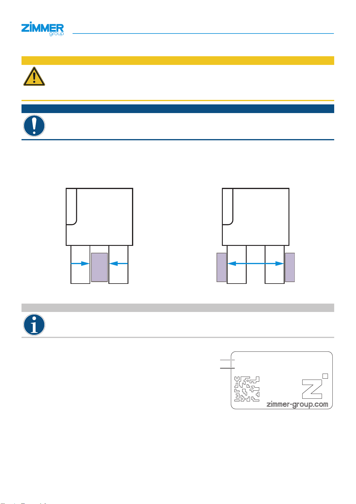
5.3 Type plate .............................................................................................................................................................................................................................8
6 Functional description ................................................................................................................................................................. 9
6.1 LED status display .............................................................................................................................................................................................................10
6.2 Control ................................................................................................................................................................................................................................10
6.3 Veried conguration examples .......................................................................................................................................................................................10
6.4 Self-locking mechanism ....................................................................................................................................................................................................10
7 Technical data ............................................................................................................................................................................ 11
7.1 Electrical specications.....................................................................................................................................................................................................11
7.2 Protection class..................................................................................................................................................................................................................11
8 Accessories/scope of delivery ................................................................................................................................................. 11
9 Transportation/storage/preservation....................................................................................................................................... 11
10 Installation .................................................................................................................................................................................. 12
10.1 Installing the product.........................................................................................................................................................................................................13
10.2 Safe shutoff for products with IO-Link..............................................................................................................................................................................14
10.3 Installing the energy supply ..............................................................................................................................................................................................15
10.4 Installing the GEP2000IL-03 power supply......................................................................................................................................................................15
10.5 Static charge ......................................................................................................................................................................................................................16
10.6 Heat dissipation .................................................................................................................................................................................................................16
10.7 Installing accessories ........................................................................................................................................................................................................16
11 Commissioning .......................................................................................................................................................................... 17
11.1 Process data .....................................................................................................................................................................................................................17
11.2 IODD Import .......................................................................................................................................................................................................................18
11.3 Handshake Data Transfer Method....................................................................................................................................................................................18
11.4 Parameters .........................................................................................................................................................................................................................19
11.4.1 ControlWord.........................................................................................................................................................................................................19
11.4.2 DeviceMode .........................................................................................................................................................................................................20
11.4.3 WorkpieceNo .......................................................................................................................................................................................................24
11.4.4 PositionTolerance ................................................................................................................................................................................................24
11.4.5 GripForce .............................................................................................................................................................................................................25
11.4.6 DriveVelocity ........................................................................................................................................................................................................25
11.4.7 BasePosition ........................................................................................................................................................................................................26
11.4.8 TeachPosition.......................................................................................................................................................................................................26
11.4.9 WorkPosition........................................................................................................................................................................................................26
11.4.10 StatusWord...........................................................................................................................................................................................................27
11.4.11 Diagnosis..............................................................................................................................................................................................................29
11.4.12 ActualPosition ......................................................................................................................................................................................................29
11.5 Minimum travel path..........................................................................................................................................................................................................30
11.6 Minimum startup path .......................................................................................................................................................................................................30
11.7 Easy Startup .......................................................................................................................................................................................................................30
11.8 Quickstart Basic Parameters ............................................................................................................................................................................................31
11.9 Starting the gripping movement.......................................................................................................................................................................................32
INSTALLATION AND OPERATING INSTRUCTIONS: LWR50L-01
DDOC01066 / d EN / 2022-05-10
Zimmer GmbH • Im Salmenkopf 5 • 77866 Rheinau, Germany • +49 7844 9138 0 • www.zimmer-group.com
Content

4
11.10 Repeated movements in the same direction...................................................................................................................................................................32
11.11 Recipe examples ...............................................................................................................................................................................................................33
11.11.1 Save recipe...........................................................................................................................................................................................................33
11.11.2 Loading a recipe..................................................................................................................................................................................................34
12 Operation....................................................................................................................................................................................35
12.1 Adjustable gripping force..................................................................................................................................................................................................35
12.2 Emergency release ............................................................................................................................................................................................................35
13 Gripping force charts................................................................................................................................................................. 35
14 Error diagnosis...........................................................................................................................................................................36
14.1 Status in LED display for error GEP2000IL-03................................................................................................................................................................38
15 Table with acyclic data (ISDU) .................................................................................................................................................. 39
16 Maintenance............................................................................................................................................................................... 41
17 Decommissioning/disposal ...................................................................................................................................................... 41
18 RoHS declaration....................................................................................................................................................................... 42
19 REACH declaration.................................................................................................................................................................... 42
20 Declaration of Incorporation ..................................................................................................................................................... 43
21 Declaration of Conformity ......................................................................................................................................................... 44
INSTALLATION AND OPERATING INSTRUCTIONS: LWR50L-01
DDOC01066 / d EN / 2022-05-10
Zimmer GmbH • Im Salmenkopf 5 • 77866 Rheinau, Germany • +49 7844 9138 0 • www.zimmer-group.com

5
1 Supporting documents
NOTICE
Read through the installation and operating instructions before installing or working with the product.
The installation and operating instructions contain important notes for your personal safety. They must be read
and understood by all persons who work with or handle the product during any phase of the product lifetime.
The documents listed below are available for download on our website www.zimmer-group.com.
• Installation and operating instructions
• Catalogs, drawings, CAD data, performance data
• Information on accessories
• Technical data sheets
• General Terms and Conditions, including warranty information.
ÖOnly those documents currently available on the website are valid.
In these installation and operating instructions, "product" refers to the product designation on the title page!
1.1 Notices and graphics in the installation and operating instructions
DANGER
This notice warns of an imminent danger to the life and health of people. Ignoring these notices can lead to
serious injury or even death.
►You absolutely must comply with the described measures for avoiding these dangers!
ÖThe warning symbols are assigned according to the type of danger.
WARNING
This notice warns of a situation that is potentially hazardous to personal health. Ignoring these notices can cause
serious injury or damage to health.
►You absolutely must comply with the described measures for avoiding these dangers!
ÖThe warning symbols are assigned according to the type of danger.
CAUTION
This notice warns of a situation that is potentially hazardous for people or that may result in material or environ-
mental damage. Ignoring these notices may result in slight, temporary injuries or damage to the product or to the
environment.
►You absolutely must comply with the described measures for avoiding these dangers!
ÖThe warning symbols are assigned according to the type of danger.
NOTICE
General notices contain usage tips and valuable information, but no warnings of dangers to health.
INFORMATION
This category contains useful tips for handling the product eciently. Failure to observe these tips will not result
in damage to the product. This information does not include any information relevant to health or workplace
safety.
INSTALLATION AND OPERATING INSTRUCTIONS:GEP2000IL-03
DDOC01219 / b EN / 2021-12-20
Zimmer GmbH • Im Salmenkopf 5 • 77866 Rheinau, Germany • +49 7844 9138 0 • www.zimmer-group.com

6
2 Safety notices
CAUTION
Risk of injury and material damage in case of non-compliance
Installation, commissioning, maintenance and repairs may only be performed by qualied specialists in
accordance with these installation and operating instructions.
The product is state-of-the-art.
It is tted to industrial machines and is used to hold, transport and store workpieces.
The following are examples of situations in which the product may cause a hazard:
• The product is not properly installed, used or maintained.
• The product is not used for its designated purpose.
• The locally applicable regulations, laws, directives or guidelines are not observed.
►The product may only be used in accordance with these installation and operating instructions and the
product's technical data. Any changes or additions to the intended use of the product, as well as modications
to the product, such as those in the following examples, require the written permission of the manufacturer:
• Use of the product under extreme conditions, such as aggressive uids or abrasive dusts
• Additional drilled holes or threads
ÖZimmer GmbH shall accept no liability for any damage caused by improper use. The operator bears sole
responsibility.
►Make sure that the power supply is disconnected before you mount, adjust, modify, maintain or repair the
product.
►Whenever work is carried out on the product, make sure that the product cannot be actuated by mistake.
►Perform maintenance tasks, renovation work or attachment work outside of the machine's danger zone when
possible.
►Do not reach into the operational range of the product.
►Observe the specied maintenance intervals and specications regarding the quality of the operating material.
►When using the product under extreme conditions, adjust the maintenance interval according to the degree of
contamination.
INSTALLATION AND OPERATING INSTRUCTIONS:GEP2000IL-03
DDOC01219 / b EN / 2021-12-20
Zimmer GmbH • Im Salmenkopf 5 • 77866 Rheinau, Germany • +49 7844 9138 0 • www.zimmer-group.com

7
3 Proper use
NOTICE
The product is only to be used in its original state with its original accessories, with no unauthorized changes and
within the stipulated parameter limits and operating conditions.
Any other or secondary use is deemed improper.
►Operate the product only in compliance with the associated installation and operating instructions.
►Operate the product only when it is in a technical condition that corresponds to the guaranteed parameters
and operating conditions.
ÖZimmer GmbH shall accept no liability for any damage caused by improper use. The operator bears sole
responsibility.
The product is designed exclusively for electric operation using a 24V DC power supply.
The product must always be mounted on materials that dissipate heat.
The product is intended for industrial use.
The product is to be used as intended in enclosed rooms for temporary gripping, handling and holding.
The product is not suitable for clamping workpieces during a machining process.
Direct contact with perishable goods/food is not permitted.
Observance of the technical data and of the installation and operating instructions are part of proper use.
4 Personnel qualication
Installation, commissioning and maintenance may only be performed by trained specialists. These persons must have read
and understood the installation and operating instructions in full.
INSTALLATION AND OPERATING INSTRUCTIONS:GEP2000IL-03
DDOC01219 / b EN / 2021-12-20
Zimmer GmbH • Im Salmenkopf 5 • 77866 Rheinau, Germany • +49 7844 9138 0 • www.zimmer-group.com

8
5 Product description
CAUTION
Reduction of the gripping force can cause personal injury and material damage
When exible components are gripped, the gripping force of the product is reduced.
Reduced gripping force can lead to personal injury or material damage, because the components that are being
gripped can no longer be securely gripped and transported.
NOTICE
►Make sure that the setting of the gripping force and the selection of the gripper nger length are correct to
prevent incorrect bracing of the gripper jaws.
ÖAn incorrect conguration or selection can lead to malfunction
5.1 Possible applications
Outside gripping Inside gripping
The product can be used for outside gripping. The product can be used for inside gripping.
MoveToWork command MoveToBase command
5.2 Forces and torques
INFORMATION
►You can nd the information in the technical data sheet on our website.
►Please contact Zimmer Customer Service if you have any questions.
5.3 Type plate
A type plate is attached to the housing of the product.
XXX
XX-XXXXXX
am
an
The article number and conrmation number are shown on the type
plate.
am Article number
an Conrmation number
INSTALLATION AND OPERATING INSTRUCTIONS:GEP2000IL-03
DDOC01219 / b EN / 2021-12-20
Zimmer GmbH • Im Salmenkopf 5 • 77866 Rheinau, Germany • +49 7844 9138 0 • www.zimmer-group.com

9
6 Functional description
The gripper jaws of the product are arranged parallel to each other on two opposing guide rails and can be moved relative
to each other.
The force of the motor is transmitted by a worm drive. A pinion and a rack generate the movement of the gripper jaws and
synchronize these movements.
Despite its small installation space, the product is suited for gripping a wide range of form-t and frictional t parts.
You can optionally adjust the gripping force to the workpiece by using the control system via IO-Link.
1Power supply
2Emergency release
3Gripper jaw
1
2
3
INSTALLATION AND OPERATING INSTRUCTIONS:GEP2000IL-03
DDOC01219 / b EN / 2021-12-20
Zimmer GmbH • Im Salmenkopf 5 • 77866 Rheinau, Germany • +49 7844 9138 0 • www.zimmer-group.com

10
6.1 LED status display
4Power/communication
5Error
4
5
6.2 Control
INFORMATION
►You can nd the information in the technical data sheet on our website.
►Please contact Zimmer Customer Service if you have any questions.
6.3 Veried conguration examples
INFORMATION
►You can nd the information in the technical data sheet on our website.
►Please contact Zimmer Customer Service if you have any questions.
6.4 Self-locking mechanism
INFORMATION
The product has a mechanical self-locking mechanism to ensure that the workpiece remains held by the product
in the event of power supply loss or failure (e.g. an emergency stop).
►Please contact Zimmer Customer Service if you have any questions.
INSTALLATION AND OPERATING INSTRUCTIONS:GEP2000IL-03
DDOC01219 / b EN / 2021-12-20
Zimmer GmbH • Im Salmenkopf 5 • 77866 Rheinau, Germany • +49 7844 9138 0 • www.zimmer-group.com

11
7 Technical data
INFORMATION
►You can nd the information in the technical data sheet on our website.
This data varies within the series, depending on the specic design.
►Please contact Zimmer Customer Service if you have any questions.
7.1 Electrical specications
INFORMATION
►You can nd the information in the technical data sheet on our website.
This data varies within the series, depending on the specic design.
►Please contact Zimmer Customer Service if you have any questions.
7.2 Protection class
NOTICE
The product achieves protection class IP40 in all mounted positions of installation.
8 Accessories/scope of delivery
INFORMATION
If any accessories not sold or authorized by Zimmer GmbH are used, the function of the product cannot be
guaranteed. Zimmer GmbH accessories are specically tailored to the individual products.
►For optional accessories and those included in the scope of delivery, refer to our website.
9 Transportation/storage/preservation
►Transport and storage of the product must be done only with the original packaging.
►If the product has already been installed on the superordinate machine unit, care must be taken during transport to
ensure that no unexpected movements can occur.
►Before commissioning the product and after transport, check all power and communication connections as well as
all mechanical connections.
►If the product is stored for an extended period, the following points are to be observed:
►Keep the storage location as dust-free and dry as possible.
►Avoid temperature uctuations/observe and adhere to the temperature range.
►Avoid wind/drafts/water condensation formation.
►Cover the product with a weatherproof, tear-resistant foil to prevent dust.
►Pack the product and do not expose it to direct sunlight during storage.
►Clean all components. There must be no soiling left on the components.
►Visually inspect all components.
►Remove all foreign substances.
►Properly remove potential corrosion spots.
►Close electrical connections using suitable covers.
INSTALLATION AND OPERATING INSTRUCTIONS:GEP2000IL-03
DDOC01219 / b EN / 2021-12-20
Zimmer GmbH • Im Salmenkopf 5 • 77866 Rheinau, Germany • +49 7844 9138 0 • www.zimmer-group.com

12
10 Installation
WARNING
Risk of injury due to uncontrolled movements
Risk of injury in case of unexpected movement of the machine or system into which the product is to be installed.
►Switch off the energy supply of the machine before any work.
►Secure the power supply against being switched on unintentionally.
►Check the machine for any residual energy that may be present.
CAUTION
Risk of injury due to uncontrolled movements
Risk of injury in the event of uncontrolled movement of the product when the power supply is connected.
►Switch off the power supply to the machine before carrying out any work.
►Secure the power supply against being switched on unintentionally.
►Check the machine for any residual energy that may be present.
NOTICE
►Installation may only be carried out by qualied personnel in accordance with these installation and operating
instructions.
►Switch off the power supply before any assembly, installation or maintenance work.
►Install the product on an appropriate mounting surface in accordance with the atness specications.
INFORMATION
Requirements for the mounting surface:
• Permissible unevenness: 0.03 mm
• Cleanliness of the mounting surfaces of the product and mounting piece (product grounding)
Further installation information:
• The mounting screws are not included in the scope of delivery.
• Strength class of the mounting screws is at least 8.8 (DIN EN ISO 4762)
►Make sure that the mounting piece is suciently rigid.
►Observe the tightening torque of the mounting screws.
►Verify the permitted load capacity of the required screw connections in accordance with VDI 2230.
INSTALLATION AND OPERATING INSTRUCTIONS:GEP2000IL-03
DDOC01219 / b EN / 2021-12-20
Zimmer GmbH • Im Salmenkopf 5 • 77866 Rheinau, Germany • +49 7844 9138 0 • www.zimmer-group.com

13
10.1 Installing the product
The product can be installed from multiple
sides.
6
7
►Insert the centering sleeves into the
provided ts on the product.
►Position the product on the mounting piece
using centering sleeves.
►Mount the product on the mounting piece
using the appropriate mounting screws.
6Mounting screw
7Centering Disc
INFORMATION
►Use an adapter plate if necessary.
►For information on optional accessories and those included in the scope of delivery, refer to our website.
INSTALLATION AND OPERATING INSTRUCTIONS:GEP2000IL-03
DDOC01219 / b EN / 2021-12-20
Zimmer GmbH • Im Salmenkopf 5 • 77866 Rheinau, Germany • +49 7844 9138 0 • www.zimmer-group.com

14
10.2 Safe shutoff for products with IO-Link
INFORMATION
For safe shutoff for IO-Link products, two contactors are switched in series with one auxiliary contact each. Here,
the auxiliary contacts monitor the status of the contactors. If one contactor does not switch, the second contactor
ensures safety. The malfunction can still be detected using the contacts.
The following example corresponds to control category3 and the PLd can be reached in any case. PLe in control
category4 can be reached only if S24V is also shut off with two channels and with error monitoring, similar to the example
above. The product cannot carry out a hazardous movement.
.
PE
..
1
..
2
..
3
..
4
.
PE
-W3
1
2
3
4
PE
Up
GND Up
Us
GND Us
PE
Up
GND Up
Us
GND Us
Up
GND Up
Us
GND Us
br
-W4
M12 5pol 5m
ws
bl
sw
gr
1
2
3
4
5
1
Power
OUT
Bosch_Timo_Plan.0004_images\image0.jpgBosch_Timo_Plan.0004_images\image1.jpg Bosch_Timo_Plan.0004_images\image2.jpg
WH/OR WH/GN GN OR WH/OR WH/GN GN OR
TX+
RX+
RX-
TX-
TX+
RX+
RX-
TX-
PE
Up
GND Up
Us
GND Us
1
2
3
4
5
1
2
3
4
5
1
2
3
4
1
2
3
4
2
3
4
5
-Q10
12
3
4
5
6
12
3
4
5
6
-Q11
12
3
4
5
6
12
3
4
5
6
Rk_1
Rk_2
-KXX2
24V IN 24V OUT
L/A IN L/A OUT
X01
GND_Up
1
GND_Us
2
PE
3
Us
4
Up
5
GND_Up
1
GND_Us
2
PE
3
Us
4
Up
5
Tx+
1
Rx+
2
Rx-
3
Tx-
4
Tx+
1
Rx+
2
Rx-
3
Tx-
4
L+
1
P24
2
L-
3
C/Q
4
N24
5
2122 21222122 2122
Power
IN
Bosch_Timo_Plan.0004_images\image3.jpg
Bosch_Timo_Plan.0004_images\image4.jpg
-K1
S24V
1
P24V
2
SGND
3
C/Q
4
PGND
5
89bl bm
cable
Ensure galvanic
isolation.
feedback circle
of Q10 & Q11
Fieldbus
bus module head
L/A IN
Fieldbus module
bus module head
L/A OUT
IO-Link master
Zimmer
IO-Link gripper
8Two contactors in series, each with an auxiliary contact
9Connection to other eld devices
bl Connection to other eldbus nodes
bm Product with IO-Linkwithout external STO cable
NOTICE
Without an externally fed power supply,the motor of the product cannot carry out an active movement and thus
cannot carry out a hazardous movement.
There is no galvanic isolation between the two voltage supplies (signal and power). There is a low-voltage
connection via ground (GND).
Because of the self-locking mechanism, the product remains in the last approached position, even if no power is
supplied.
INSTALLATION AND OPERATING INSTRUCTIONS:GEP2000IL-03
DDOC01219 / b EN / 2021-12-20
Zimmer GmbH • Im Salmenkopf 5 • 77866 Rheinau, Germany • +49 7844 9138 0 • www.zimmer-group.com

15
10.3 Installing the energy supply
NOTICE
The cables that are used by Zimmer GmbH feature a minimum bending radius of 10 x the outer diameter.
This bending radius must not be undershot!
►Freely suspended cables must be secured to prevent excessive motion loads or pinching.
►The contacts of the energy supply must be dry, clean and undamaged at all times.
ÖDamage to the contacts can result in malfunction of the product.
►Connect the power supply cable to the
control system of the product.
10.4 Installing the GEP2000IL-03 power supply
pin Color Function Explanation
3
21
45
M12 5-pin plug
1Brown + 24 V DC sensor IO-Link communication supply
2White + 24 V DC actuator Actuator supply voltage
3Blue GND sensor 0 V DC sensor supply voltage
4Black C/Q IO-Link communication
5Gray GND actuator 0 V DC actuator supply voltage
►Connect the product to the IO-Link master.
►Ensure the proper voltage supply.
INSTALLATION AND OPERATING INSTRUCTIONS:GEP2000IL-03
DDOC01219 / b EN / 2021-12-20
Zimmer GmbH • Im Salmenkopf 5 • 77866 Rheinau, Germany • +49 7844 9138 0 • www.zimmer-group.com

16
10.5 Static charge
CAUTION
Material damage from static charge
Material damage can result from contact of ESD-sensitive parts with the product.
►It is mandatory to ground the gripper ngers.
Grounding is also recommended in applications that require high EMC shielding.
The movement of the gripper jaws creates low voltages as a result of static charging. These charges cannot be dissipated if
the product is mounted on an insulating surface and if discharge is also not possible through the workpiece.
10.6 Heat dissipation
In the event of high ambient temperatures, the product must be installed on heat-dissipating materials.
If the product is operated under very high ambient temperatures and with fast clock cycles on an ongoing basis, this might
reduce its service life.
INFORMATION
ÖThe cycle time must therefore be reduced as the temperature increases.
10.7 Installing accessories
NOTICE
Before installing an accessory, make sure it is suitable for use with the selected variant.
►You can nd information on our website.
►Please contact Zimmer Customer Service if you have any questions.
INSTALLATION AND OPERATING INSTRUCTIONS:GEP2000IL-03
DDOC01219 / b EN / 2021-12-20
Zimmer GmbH • Im Salmenkopf 5 • 77866 Rheinau, Germany • +49 7844 9138 0 • www.zimmer-group.com

17
11 Commissioning
11.1 Process data
There is an option to control the product only with the process data that is transmitted in each cycle.
Outputs: Process data from the IO-Link master to the product!
Name Data type
ControlWord UINT16
DeviceMode UINT8
WorkpieceNo UINT8
Reserve UINT8
PositionTolerance UINT8
GripForce UINT8
DriveVelocity UINT8
BasePosition UINT16
Reserve UINT16
TeachPosition UINT16
WorkPosition UINT16
Control system Gripper
Input
Output
Name Data type
StatusWord UINT16
Diagnosis UINT16
ActualPosition UINT16
INSTALLATION AND OPERATING INSTRUCTIONS:GEP2000IL-03
DDOC01219 / b EN / 2021-12-20
Zimmer GmbH • Im Salmenkopf 5 • 77866 Rheinau, Germany • +49 7844 9138 0 • www.zimmer-group.com

18
11.2 IODD Import
►Import the IODD (device description) into the control system.
►Go to our website.
►Select the desired product.
►Download the corresponding .zip le via the Download IODD link.
ÖYou will need the .zip le for import into the control system.
ÖAs soon as the hardware conguration is complete and the IO-Link connection to the product is established, data will be
displayed in the process input data.
ÖSome control systems demand a byte swap to bring this process data into a logical sequence.
►Look at bit 6 (GripperPLCActive) in the StatusWord to determine whether a byte swap is necessary.
►Determine whether bit 6 is active in the rst or second byte of the StatusWord.
ÖBit 6 is active in the rst byte: The bytes already have the correct sequence.
►Continue with the commissioning.
ÖBit 6 is active in the second byte.
►Apply a byte swap, refer to the "StatusWord" section.
INFORMATION
The product is controlled via IO-Link by means of the cyclical process data as well as the acyclic service data with
a cycle time of 5ms.
►It is mandatory to verify the process data!
11.3 Handshake Data Transfer Method
The handshake method makes it possible to transfer the process data about the product. All process data described in the
following sections must be transferred with the handshake.
►Send the ControlWord = 0x0001 to the product.
ÖThe data transfer was started.
►Check the response of the product by using Statusbit 12 = TRUE (data transfer OK).
►Send the ControlWord = 0x0000 to stop the data transfer.
ÖThe data transmission is complete when the product sends back Statusbit 12 = DataTransferOK = FALSE.
INFORMATION
►For examples, refer to the "Quickstart Basic Parameters" section.
INSTALLATION AND OPERATING INSTRUCTIONS:GEP2000IL-03
DDOC01219 / b EN / 2021-12-20
Zimmer GmbH • Im Salmenkopf 5 • 77866 Rheinau, Germany • +49 7844 9138 0 • www.zimmer-group.com

19
11.4 Parameters
11.4.1 ControlWord
NOTICE
In the ControlWord parameter, only one single bit or the value 0 may be set at a time. Only the values listed in the
following table are valid.
Parameter Decimal value Hexadecimal value
DataTransfer 1 0x0001
WritePDU 2 0x0002
ResetDirectionFlag 4 0x0004
Teach 8 0x0080
MoveToBase 256 0x0100
MoveToWork 512 0x0200
JogToWork + 1024 0x0400
JogToBase - 2048 0x0800
ErrorReset 32768 0x8000
Name ControlWord
Data format UINT16
Permission Write
Transfer Cyclical
Value range 0 ... 65535
Bit 15 Bit 14 Bit 13 Bit 12 Bit 11 Bit 10 Bit 9 Bit 8
Byte 1 ErrorReset - - - JogToBase JogToWork
MoveToWork
MoveToBase
Bit 7 Bit 6 Bit 5 Bit 4 Bit 3 Bit 2 Bit 1 Bit 0
Byte 2 - - - - Teach ResetDirec-
tionFlag
WritePDU
DataTransfer
Bit 0: DataTransfer
When this bit is set, the product accepts the data transferred in the process data.
Bit 1: WritePDU
Setting this bit tells the product that it should write the current process data to the selected workpiece recipe.
Bit 2: ResetDirectionFlag
Setting this bit tells the product that the direction ag needs to be reset. This makes a repeated movement to a position
possible. This is logical during a switchover of workpiece recipes.
Bit 3: Teach
Setting this bit tells the product to save the current position as the TeachPosition in the selected WorkpieceNo. This only
works if there is no "0" that is transmitted in the workpiece number.
Bit 8: MoveToBase
Setting this bit tells the product to move toward the BasePosition.
Bit 9: MoveToWork
Setting this bit tells the product to move toward the WorkPosition.
INSTALLATION AND OPERATING INSTRUCTIONS:GEP2000IL-03
DDOC01219 / b EN / 2021-12-20
Zimmer GmbH • Im Salmenkopf 5 • 77866 Rheinau, Germany • +49 7844 9138 0 • www.zimmer-group.com

20
Bit 10: JogToWork
Setting this bit in the ControlWord puts the product in jog mode and slowly moves it toward the WorkPosition. If the bit is
reset, the product stops.
Bit 11: JogToBase
Setting this bit in the ControlWord puts the product in jog mode and slowly moves it toward the BasePosition. If the bit is
reset, the product stops.
Bit 15: ErrorReset
This bit can be used to acknowledge all errors that can be reset. Whether an error can be reset is shown in the "Error
Diagnosis" section.
11.4.2 DeviceMode
INFORMATION
DeviceMode is used to select one of the following travel modes: universal operation, outside gripping or inside
gripping. Zimmer GmbH recommends DeviceMode63, 73 and 103.
Input Mode Description
63 Outside gripping with subsequent
current feed
Like Mode 60, but with an activated subsequent current feed
for a time of 500ms when the direction of movement is Work.
To achieve the best gripping results, the gripped workpiece
must be transported further during the subsequent current
feed.
73 Inside gripping with subsequent
current feed
Like Mode 70, but with an activated subsequent current feed
for a time of 500ms when the direction of movement is Base.
To achieve the best gripping results, the gripped workpiece
must be transported further during the subsequent current
feed.
103 Universal operation with
subsequent current feed
Like Mode 100, but with an activated subsequent current feed
for a time of 500ms in both directions.
To achieve the best gripping results, the gripped workpiece
must be transported further during the subsequent current
feed.
11 Activate jog mode. Product is in jog mode and moves slowly in the selected
direction as long as the respective bit is active in the
ControlWord.
50 Positioning mode Product moves in the PositionProle. The movement speed is
congured using the DriveVelocity parameter.
60 Outside gripping Inward with the desired gripping force and speed, outward at
high speed.
70 Inside gripping Outward with the desired gripping force and speed, inward at
high speed.
100 Universal mode Inside and outside gripping, both movements at the same
speed.
Name DeviceMode
Data format UINT8
Permission Write
Transfer Cyclical
Value range 11, 50, 60, 63, 70, 73, 100, 103
INSTALLATION AND OPERATING INSTRUCTIONS:GEP2000IL-03
DDOC01219 / b EN / 2021-12-20
Zimmer GmbH • Im Salmenkopf 5 • 77866 Rheinau, Germany • +49 7844 9138 0 • www.zimmer-group.com
This manual suits for next models
3
Table of contents
Other Zimmer Industrial Electrical manuals
Popular Industrial Electrical manuals by other brands

Eaton
Eaton PHM25-16FUSE Instruction leaflet

Ravas
Ravas SAFECHECK Installation and user manual

Murata
Murata GRM155R71C683KA88 Series Reference sheet

Murata
Murata GRM0225C1E8R0CA03 Series Reference sheet

Murata
Murata GRM0335C1E3R6BA01 Series Reference sheet

Murata
Murata GRM033R61E103KA12 Series Reference sheet

Murata
Murata GRT21BR61A106KE01 Series Reference sheet

Danfoss
Danfoss ECL Comfort A260 Mounting guide

Murata
Murata GRM186R60J226ME15 Series Reference sheet

Murata
Murata GRM0225C1E5R2BA03 Series Reference sheet

Murata
Murata GRM1557U1A472JA01 Series Reference sheet

Murata
Murata GRM1885C1H300JA01 Series Reference sheet