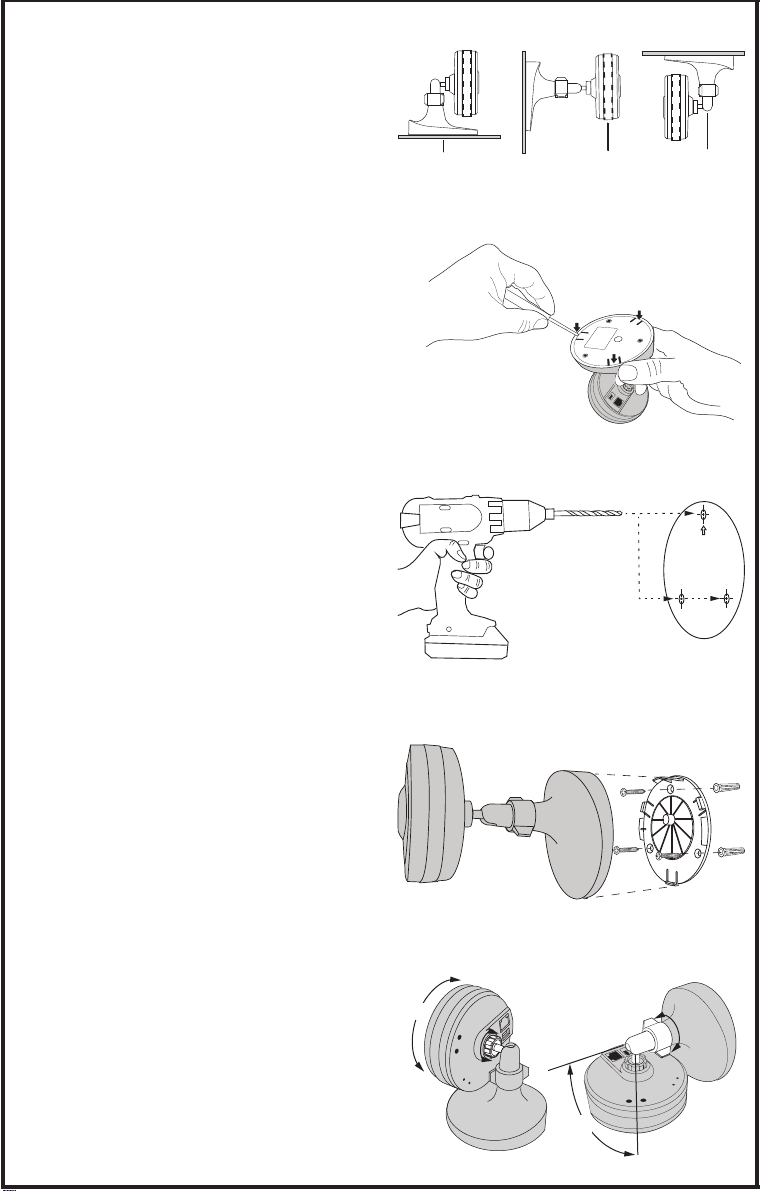
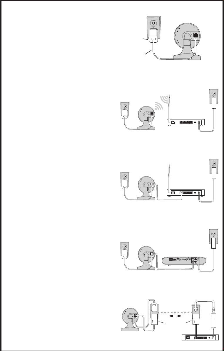
➒Camera & Network Software Setup
Refer to the Inial IP Camera & 2GIG NVR
Soware Setup sheet included with the camera
for step-by-step details on seng up the various
inial camera and network system sengs.
• Determine the camera’s IP address
• Set a stac IP address for the camera
• Setup oponal DDNS Server
• Setup the camera’s port numbers
• Setup the router’s Port Forwarding
• Connect to the camera with a browser
Aer the inial setup, refer to the 2GIG Camera
Operaon Instrucons included on the Support
CD for details on all camera sengs available.
➓Audio/Snapshot/Playback Functions
To enable Audio (including Bi-direconal audio)
on the 2GIG IP Cameras, Internet Explorer
with an AcveX plug-in is required. You cannot
receive audio on Google Chrome, Apple Safari,
Mozilla Firefox, Opera browsers.
There are two steps to install AcveX on
Internet Explorer.
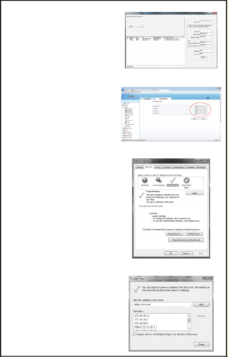
Internet Explorer Security Tab
1. Access this menu in Internet Explorer
through the TOOLS -> INTERNET OPTIONS
menu
2. Click on the SECURITY Tab. Click TRUSTED
SITES. Click SITES.
3. Enter the IP Address of the IP Camera.
4. Click CLOSE.
5. Click CUSTOM LEVEL.
6. Scroll down to DOWNLOAD SIGNED
ACTIVEX CONTROLS & DOWNLOAD
UNSIGNED ACTIVEX CONTROLS
7. Set both of these opons to PROMPT.
Click OK.
8. Click OK to Save changes
Installing ActiveX control
1. With the Internet Explorer Web browser,
Login to the Live Video screen of the IP
Camera.
2. Click on the link “Click here to use short
delay Plugin for Live Video.” Click INSTALL
on the prompt that appears. Live video
with Audio Controls/Snapshot/Playback
should work on the tab.
Maximum Video streams supported
The IP Cameras support Flash and AcveX
technology for video streaming. 10 concurrent
video streams are supported over AcveX, two
streams are supported with Flash.
Figure 22. IP Search Tool Results
Figure 23. Camera Port Configuraon
Figure 24. IE Security Tab
Figure 25. Trusted Sites Seng
➑iOS Application
An Apple device can run the 2GIG Video
Applicaon to monitor 2GIG cameras.
First set up the applicaƟon while the Apple
device is connected to the Local Area Network
that the camera(s) are installed on. To monitor
the camera(s) remotely, on the Internet, from
outside the Local Area Network that the
camera(s) are installed on, Port Forwarding
must be set in the router. Refer to the IniƟal
IP Camera & 2GIG NVR SoŌware Setup sheet
included with the camera for details on seƫng
router Port Forwarding.
Adding 2GIG IP Cameras
1. Aer downloading the 2GIG Video app
from the Apple store, press OPEN.
2. Press AUTO DISCOVERY magnifying glass
at the top of the screen. The EXISTING
DEVICES screen will display.
3. Press AUTO DISCOVERY, then SEARCH.
The app will search for 2GIG IP Cameras on
the Local Area Network. The IP addresses
of the camera(s) discovered will be listed.
4. Click on a camera, then enter the default
Username and Password. (admin / admin)
then press OK.
5. If the camera’s username and password is
OK the camera’s IP address will turn blue.
6. Repeat Steps 6 & 7 for addional cameras.
7. Press the blue camera IP address to select
the camera. A blue check mark will show.
8. Press ADD. The ADD SUCCEED message
should be displayed. Press OK.
9. Press the HOME icon. Press the +sign to
display the available cameras.
10. Select a Camera.
The camera’s view will be displayed. Opon
buons display are on the boom of the
screen. Mulple camera views can be led,
video snapshots, full screen mode, and other
opons are available.
For details on using the app, refer to the app’s
built-in help instrucons accessed through the
gear setup icon.
Figure 20. Selecng Auto Discovery
Figure 21. Discovered Cameras
Figure 21. Viewing Camera Video
➐Android 2GIG Video Application
An Android device can run the 2GIG Video
Applicaon to monitor 2GIG cameras.
First set up the applicaƟon while the Android
device is connected to the Local Area Network
that the camera(s) are installed on. To monitor
the camera(s) remotely, on the Internet, from
outside the Local Area Network that the
camera(s) are installed on, Port Forwarding
must be set in the router. Refer to the IniƟal
IP Camera & 2GIG NVR SoŌware Setup sheet
included with the camera for details on seƫng
router Port Forwarding.
Adding 2GIG IP Cameras
1. Aer downloading the 2GIG Video app
from the Google Play store, launch the
app.
2. Press AUTO DISCOVERY at the boom of
the screen.
3. Enter the default Username and Password.
(admin / admin)
4. Press SEARCH. The app will search for
2GIG IP Cameras on the Local Area
Network. The camera(s) discovered will be
listed.
5. Select the 2GIG Camera(s) with the blue
check mark, then press ADD. The ADD
SUCCEED message should be displayed.
6. Press DEVICE LIST. The IP Camera(s)
names are displayed.
7. Select a Camera.
8. Select a video stream to view (cameras
can send two video steams of different
quality).
The camera’s view will be displayed. Opon
buons display are on the boom of the
screen. Mulple camera views can be led,
video snapshots, full screen mode, and other
opons are available.
For details on using the app, refer to the app’s
built-in help instrucons accessed through the
gear setup icon.
Figure 16. Auto Discovery Buon
Figure 17. Auto Discovery of Cameras
Figure 18. Online Device List
Figure 19. Viewing Camera Video
2GIG Video Troubleshooting
Q: I cannot see the IP Camera on my network
A: Make sure that the IP Camera is powered on. Ensure that
the power supply is plugged into the wall.
On the back of the 2GIG-CAM-100W IP Camera, the Power
LED should be solid red. Ensure that the network cable is
connected to the router/switch on the Local Area Network.
If using WPS, ensure that router supports WPS and is acve
when syncing wirelessly with the IP Camera. If using a tablet
or smart phone to detect the IP Camera, make sure the
mobile device is on the same network as the IP Camera(s).
Q: The image is not clear at night
A: Check the IP cameras’ lens for any smudges or moisture
lefrom fingerprints. Wipe down with a non-abrasive towel.
Also make sure that no object is blocking the path of the IR
Emier. Check the Sensor Sengs in the IP Camera to verify
that the Day/Night opon is set to Auto. The WDR feature
of the IP camera may need to be disabled when the IR LEDs
are acve.
Q: I cannot see Video when I am away from my house.
A: The ports needed to see the video from a mobile device is
30001. Port forward this port in the router. Use both UDP/TCP
for the protocol opon in the Port Forwarding secon of the
router. When registering the device on the 2GIG Video app,
the WAN IP address will be needed from the router. The WAN
IP Address can be found at the home router.
Q: I cannot view mulƟple high resoluƟon video streams on
my mobile device.
A: High resoluon streams require high amounts of data to be
processed on mobile devices. The applicaon and mobile
device have a limit on how many high resoluon streams can
be processed.
Q: How do I format the SD card for recording?
A: Insert the SD Card into the IP Camera(s). Refer to the
installaon manual for the exact locaon of the SD Card slot.
Login to the IP Camera(s). Default User Name and Password
is admin. Navigate to Device Configuraon-> Record
Configuraon -> Record Directory. Select SD Card and press
the Format Buon.
Q: What if SD Card formaƫng fails?
A: Remove the SD Card and format it on another device such
as a PC or Camera that supports SD cards. Aer formang,
re-insert the SD Card into the IP Camera(s) and format the
SD card again in the IP Camera(s). Note that the file SD Card
format needs to be ext4.
Q: What type of Wi-Fi networks are supported?
A: The Wi-Fi IP Camera works on 2.4Ghz compable N and G
networks. It is not supported on 5GHz compable N and AC
networks.
Q: How many users can stream video at the same Ɵme on
the IP Cameras?
A: When connected to the IP Camera using Flash technology
the maximum number of video connecons is 2. When
connected to the IP Camera using AcveX technology, the
maximum number of video connecons is 10.
Q: How long does it take to update the firmware on the IP
Camera?
A: The Update Tool is designed to update the IP Camera
firmware. Note that the fi
rmware update process can take
between 5 and 10 minutes for both wired and wireless
updates.
Regulatory Information
WARNING: Changes or modifications not expressly approved by Nortek Security
& Control could void the user’s authority to operate the equipment.
This device complies with FCC Part 15 Rules and Industry Canada licence-
exempt RSS standard(s). Operation is subject to the following two conditions:
(1) this device may not cause interference, and (2) this device must accept any
interference, including interference that may cause undesired operation of the
device.
Cét appareil est conforme la norme d’Industrie Canada exempts de licence RSS.
Son fonctionnement est soumis aux deux conditions suivantes: (1) cét appareil
ne peut pas provoquer d’interférences, et (2) c’et appareil doit accepter toute
interférence, y compris les interférence, y compris les interférences qui peuvent
causer un mauvais fonctionnement de la dispositif.
Limited Warranty
This Nortek Security & Control LLC product is warranted against defects in
material and workmanship for two (2) years. This warranty extends only to
wholesale customers who buy direct from Nortek Security & Control LLC
or through Nortek Security & Control normal distribution channels. Nortek
Security & Control does not warrant this product to consumers. Consumers
should inquire from their selling dealer as to the nature of the dealer’s warranty,
if any.
There are no obligations or liabilities on the part of Nortek Security & Control for
consequential damages arising out of or in connection with use or performance
of this product or other indirect damages with respect to loss of property,
revenue, or profit, or cost of removal, installation, or reinstallation. All implied
warranties for functionality, are valid only until the warranty expires. This Nortek
Security & Control Warranty is in lieu of all other warranties express or implied.
Nortek Security & Control LLC
1950 Camino Vida Roble, Suite 150
Carlsbad, CA 92008-6517 USA
For technical support in the USA and Canada:
Dial: 855-2GIG-TECH (855-244-4832)
Email: 2gigtechsupport@nortek.com
Visit www.2GIG.com or dealer.2gig.com technical support hours of operaon
For technical support outside of the USA and Canada:
Contact your regional distributor
Visit www.nortekcontrol.com for a list of distributors in your region
Copyright © 2015 Nortek Security & Control LLC 10004379 X20
PRINTER’S INSTRUCTIONS:
INSTALL INSTR SHEET 2GIG-CAM-100W; P/N: 10004379 X20; INK: BLACK; MATERIAL: 20# MEAD BOND; SIZE: 11.000” x 17.000”; TOLERANCE ± .125”; SCALE: 1-1; SIDE 2 OF 2