3P PRINZ Pompe 3P M Series Instructions for use

/INSTRUCTION & MAINTENANCE MANUAL
M Series
®
®

PUMP IDENTIFICATION
- Model: _______________________________
- Serial Number: _______________________________
- Date of Manufacturing: _______________________________
- Applicable Directives: 2006/42/CE
- Applicable Standards: UNI EN ISO 12100:2010;
UNI EN ISO 13732-1:2009;
UNI EN 809:2009;
UNI EN 953:2009
3P Prinz S.r.l. hereby declares, under its sole responsibility, that the above-mentioned pump is in conformity
with the provisions of the Machinery Directive, as an incomplete Equipment to be incorporated in another
Machinery (Directive 2006/42/CE).
The above-mentioned pump must not be put into service until the relative piece of Machinery, in which it is
to be incorporated, is declared in conformity with the provisions of Machinery Directive 2006/42/CE and the
other Directives eventually applicable.
Lucca: / / Silvia Marianetti
Legal Representative
3P Prinz s.r.l - PUMPS MANUFACTURING COMPANY
Via Enrico Mattei, n.293/R, 55100
MUGNANO (LU) Italy

DECLARATION OF INCORPORATION
- MANUFACTURER: 3P PRINZ S.r.l. - Via Enrico Mattei, n.293/R,
55100 - Mugnano (Lucca) Italy
PUMP IDENTIFICATION
- Model: _______________________________
- Serial Number: _______________________________
- Date of Manufacturing: _______________________________
- Applicable Directives: 2006/42/CE
- Applicable Standards: UNI EN ISO 12100:2010;
UNI EN ISO 13732-1:2009;
UNI EN 809:2009;
UNI EN 953:2009
3P Prinz S.r.l. hereby declares, under its sole responsibility, that the above-mentioned pump is in conformity
with the provisions of the Machinery Directive, as an incomplete Equipment to be incorporated in another
Machinery (Directive 2006/42/CE).
The above-mentioned pump must not be put into service until the relative piece of Machinery, in which it is
to be incorporated, is declared in conformity with the provisions of Machinery Directive 2006/42/CE and the
other Directives eventually applicable.
Lucca: / / Silvia Marianetti
Legal Representative
3P Prinz s.r.l - PUMPS MANUFACTURING COMPANY
Via Enrico Mattei, n.293/R, 55100
MUGNANO (LU) Italy
Vat. N° 06390230487
Phone. +39 0583 491183 - Fax +39 0583 954659
1
®

CE DECLARATION OF CONFORMITY
- MANUFACTURER: 3P PRINZ S.r.l. - Via Enrico Mattei,
n.293/R, 55100 - Mugnano (Lucca) Italy
PUMP IDENTIFICATION
- Model: _______________________________
- Serial Number: _______________________________
- Date of manufacturing: _______________________________
- Applicable Directives: 2006/42/CE; 2006/95/CE; 2004/108/CE
- Applicable Standards: UNI EN ISO 12100 :2010;
UNI EN ISO 13732-1:2009;
UNI EN 809:2009;
UNI EN 953:2009
- Marking:
3P Prinz S.r.l. hereby declares, under its sole responsibility, that the above-mentioned electric pump is in
conformity with the provisions of the Machinery Directive (Directive 2006/42/CE).
The above-mentioned electric pump has undergone a risk evaluation as per Directive 2006/42/CE, designed
and tested in accordance with the above-mentioned Standards.
Lucca: / / Silvia Marianetti
Legal Representative
2
PUMP IDENTIFICATION
- Model: _______________________________
- Serial Number: _______________________________
- Date of manufacturing: _______________________________
- Applicable Directives: 94/9/CE, 2006/42/CE
DIRECTIVE 94/9/CE (ATEX)
- Applicable Standards: EN 1050, ENl127-1, EN 13463-1, EN 13463-5, EN 13463-8
- Technical Dossier: MCA 01.01
- Marking: II 2 G c k TX
3P Prinz S.r.l. herbey declares, under its sole responsibility, that the above-mentioned electric pump satises
the Directive for equipment and protective systems intended for use in potentially explosive atmospheres as
per 94/9/CE (ATEX) (D.P.R. 23/03/98 no. 126) applicable to it.
The above-mentioned electric pump has undergone a risk evaluation as per Machinery Directive and ATEX,
including an ignition risk evaluation in accordance with Standards UNI EN 13463-1, EN 13463-5 and EN
13463-8.
DIRECTIVE 2006/42/CE (MACHINERY)
- Applicable Standards: UNI EN 1127-1:2011;
UNI EN 13463-1:2009;
UNI EN 13463-5:2011, UNI EN 13463-8:2004
3P Prinz S.r.l. in addition declares that the above-mentioned pump is in conformity with the provisions of the
Machinery Directive, as an incomplete equipment to be incorporated in another machine (Directive 2006/42/
CE). The above-mentioned pump must not be put into service until the relative piece of Machinery, in which
it is to be incorporated, is declared in conformity with the provisions of Machinery Directive 2006/42/CE and
the other Directives eventually applicable.
Lucca: / / Silvia Marianetti
Legal Representative
3P Prinz srl - PUMPS MANUFACTURING COMPANY
Via Enrico Mattei, n.293/R, 55100
MUGNANO (LU) Italy
Vat. N° 06390230487
Phone. +39 0583 491183 - Fax +39 0583 954659
3P Prinz s.r.l - PUMPS MANUFACTURING COMPANY
Via Enrico Mattei, n.293/R, 55100
MUGNANO (LU) Italy
®

PUMP IDENTIFICATION
- Model: _______________________________
- Serial Number: _______________________________
- Date of manufacturing: _______________________________
- Applicable Directives: 2006/42/CE; 2006/95/CE; 2004/108/CE
- Applicable Standards: UNI EN ISO 12100 :2010;
UNI EN ISO 13732-1:2009;
UNI EN 809:2009;
UNI EN 953:2009
- Marking:
3P Prinz S.r.l. hereby declares, under its sole responsibility, that the above-mentioned electric pump is in
conformity with the provisions of the Machinery Directive (Directive 2006/42/CE).
The above-mentioned electric pump has undergone a risk evaluation as per Directive 2006/42/CE, designed
and tested in accordance with the above-mentioned Standards.
Lucca: / / Silvia Marianetti
Legal Representative
CE DECLARATION OF CONFORMITY
- MANUFACTURER: 3P PRINZ S.r.l. - Via Enrico Mattei, n.293/R,
55100 - Mugnano (Lucca) Italy
PUMP IDENTIFICATION
- Model: _______________________________
- Serial Number: _______________________________
- Date of manufacturing: _______________________________
- Applicable Directives: 94/9/CE, 2006/42/CE
DIRECTIVE 94/9/CE (ATEX)
- Applicable Standards: EN 1050, ENl127-1, EN 13463-1, EN 13463-5, EN 13463-8
- Technical Dossier: MCA 01.01
- Marking: II 2 G c k TX
3P Prinz S.r.l. herbey declares, under its sole responsibility, that the above-mentioned electric pump satises
the Directive for equipment and protective systems intended for use in potentially explosive atmospheres as
per 94/9/CE (ATEX) (D.P.R. 23/03/98 no. 126) applicable to it.
The above-mentioned electric pump has undergone a risk evaluation as per Machinery Directive and ATEX,
including an ignition risk evaluation in accordance with Standards UNI EN 13463-1, EN 13463-5 and EN
13463-8.
DIRECTIVE 2006/42/CE (MACHINERY)
- Applicable Standards: UNI EN 1127-1:2011;
UNI EN 13463-1:2009;
UNI EN 13463-5:2011, UNI EN 13463-8:2004
3P Prinz S.r.l. in addition declares that the above-mentioned pump is in conformity with the provisions of the
Machinery Directive, as an incomplete equipment to be incorporated in another machine (Directive 2006/42/
CE). The above-mentioned pump must not be put into service until the relative piece of Machinery, in which
it is to be incorporated, is declared in conformity with the provisions of Machinery Directive 2006/42/CE and
the other Directives eventually applicable.
Lucca: / / Silvia Marianetti
Legal Representative
Vat. N° 06390230487
Phone. +39 0583 491183 - Fax +39 0583 954659
3P Prinz s.r.l - PUMPS MANUFACTURING COMPANY
Via Enrico Mattei, n.293/R, 55100
MUGNANO (LU) Italy
Vat. N° 06390230487
Phone. +39 0583 491183 - Fax +39 0583 954659
3
®

CE DECLARATION OF CONFORMITY
- MANUFACTURER: 3P PRINZ S.r.l. - Via Enrico Mattei, n.293/R,
55100 - Mugnano (Lucca) Italy
PUMP IDENTIFICATION
- Model: _______________________________
- Serial Number: _______________________________
- Date of Manufacturing: _______________________________
- Electric Motor Power / Polarity: _______________________________
- Voltage / Phase / Frequency: _______________________________
DIRECTIVE 2006/42/CE; 2006/95/CE; 2004/108/CE (MACCHINE)
- Applicable Standards: UNI EN ISO 12100 :2010;
UNI EN ISO 13732-1:2009
UNI EN 809:2009;
UNI EN 953:2009
3P Prinz S.r.l. hereby declares, under its sole responsibility, that the above-mentioned electric pump is in
conformity with the provisions of the Machinery Directive (Directive 2006/42/CE).
DIRECTIVE 94/9/CE (ATEX)
- Applicable Standards: UNI EN 1127-1:2011, UNI EN 13463-1:2009,
UNI EN 13463-5:2011, UNI EN 13463-8:2004
- Technical Dossier: MCA 01.01
- Marking: II 2 G c k TX
3P Prinz S.r.l. hereby declares, under its sole responsibility, that the above-mentioned electric pump satises
the Directive for equipment and protective systems intended for use in potentially explosive atmospheres as
per 94/9/CE (ATEX) (D.P.R. 23/03/98 no. 126) applicable to it.
The above-mentioned electric pump has undergone a risk evaluation as per Machinery Directive and ATEX,
including an ignition risk evaluation in accordance with Standards UNI EN 13463-1, EN 13463-5 and EN
13463-8.
Lucca: / / Silvia Marianetti
Legal Representative
®
3P Prinz srl - PUMPS MANUFACTURING COMPANY
Via Enrico Mattei, n.293/R, 55100
MUGNANO (LU) Italy
Vat. N° 06390230487
Phone. +39 0583 491183 - Fax +39 0583 954659
4

PUMP IDENTIFICATION
- Model: _______________________________
- Serial Number: _______________________________
- Date of Manufacturing: _______________________________
- Electric Motor Power / Polarity: _______________________________
- Voltage / Phase / Frequency: _______________________________
DIRECTIVE 2006/42/CE; 2006/95/CE; 2004/108/CE (MACCHINE)
- Applicable Standards: UNI EN ISO 12100 :2010;
UNI EN ISO 13732-1:2009
UNI EN 809:2009;
UNI EN 953:2009
3P Prinz S.r.l. hereby declares, under its sole responsibility, that the above-mentioned electric pump is in
conformity with the provisions of the Machinery Directive (Directive 2006/42/CE).
DIRECTIVE 94/9/CE (ATEX)
- Applicable Standards: UNI EN 1127-1:2011, UNI EN 13463-1:2009,
UNI EN 13463-5:2011, UNI EN 13463-8:2004
- Technical Dossier: MCA 01.01
- Marking: II 2 G c k TX
3P Prinz S.r.l. hereby declares, under its sole responsibility, that the above-mentioned electric pump satises
the Directive for equipment and protective systems intended for use in potentially explosive atmospheres as
per 94/9/CE (ATEX) (D.P.R. 23/03/98 no. 126) applicable to it.
The above-mentioned electric pump has undergone a risk evaluation as per Machinery Directive and ATEX,
including an ignition risk evaluation in accordance with Standards UNI EN 13463-1, EN 13463-5 and EN
13463-8.
Lucca: / / Silvia Marianetti
Legal Representative
CAP.1 PREFACE ................................................................................................................................6
1.1 Introduction ........................................................................................................................................ 6
1.2 Warranty ............................................................................................................................................... 8
CAP.2 CARRIAGE, PACKAGING AND HANDLING ............................................................................ 9
2.1 Carriage and packaging ..................................................................................................................... 9
2.2 Handling .............................................................................................................................................. 10
CAP.3 INSTALLATION ................................................................................................................. 11
3.1 General installation regulations .................................................................................................. 11
CAP.4 SAFETY ........................................................................................................................... 13
4.1 General safety regulations .............................................................................................................13
4.2 Information on the risks that cannot be eliminated by the measures taken by the
designer......................................................................................................................................................14
CAP.5 NOISE LEVEL.......................................................................................................................... 15
5.1 Noise Level.......................................................................................................................................... 15
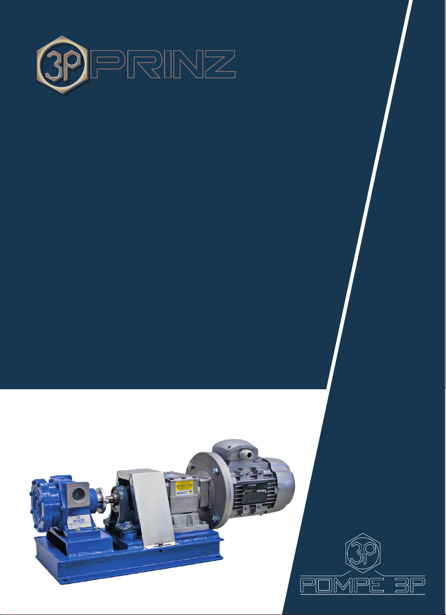
CAP.6 DESCRIPTION OF THE PUMPS ............................................................................................. 16
6.1 Volumetric pumps “M” Series (mono-body).................................................................................... 16
6.2 Working principle of the hollow disk pump...................................................................................... 17
CAP.7 USAGE OF THE PUMP ............................................................................................................ 18
7.1 Operating instructions for 3P “M” Series pumps ............................................................................. 19
CAP.8 MAINTENANCE ................................................................................................................ 20
8.1 General Rules ................................................................................................................................. 20
8.2 Maintenance of 3P “M” Series pumps....................................................................................... 20
CAP.9 ACCESSORIES ..................................................................................................................... 21
9.1 Filter.................................................................................................................................................... 21
9.2 Heating covers ................................................................................................................................... 21
9.3 Pressure relief valve ........................................................................................................................ 22
CAP.10 TROUBLESHOOTING ........................................................................................................ 23
10.1 Causes of malfunction ................................................................................................................. 23
10.1.1 Lack of suction ............................................................................................................................ 23
10.1.2 Insucient ow ............................................................................................................................. 23
10.1.3 Zero ow rate ................................................................................................................................. 24
10.1.4 Excessivepowerabsorption..........................................................................................................24
10.1.5 Noise and vibrations ..................................................................................................................... 25
CAP.11 DECOMMISSIONING ......................................................................................................... 26
11.1 Pump Decommissioning ...................................................................................................... 26
CAP.12 SPARE PARTS ...................................................................................................................... 27
12.1 Spare Parts for “M” Series (mono-body) pumps .........................................................................27
12.1.1 Exploded view for “M” Series pumps (double radial seal) ...........................................................27
12.1.2 Exploded view for “M” Series pumps (internal mechanical seal) ...............................................28
12.1.3 Exploded view for “M” Series pumps (external mechanical seal) ............................................29
12.1.4 Exploded view for “M” Series pumps (packing type seal) ...........................................................30
TABLE OF CONTENTS
®
Vat. N° 06390230487
Phone. +39 0583 491183 - Fax +39 0583 954659
5

CH.1 PREFACE
1.1 INTRODUCTION
3P Prinz S.r.l. thanks you very much for choosing a 3P volumetric pump; please also be advised
that all pumps manufactured by the company are produced while taking into account the most
advanced technologies and selecting the most appropriate materials.
All pump parts are subject to strict controls, the castings are pressure tested and, following
the assembly stage, the pump is tested; material analysis, hydraulic test and functional test
certicates are provided on request.
As it can be seen from the pump you have purchased, the body that contains the impeller, i.e.
the actual pumping part, is xed onto the base, bearing the inlet and outlet ports, with a series
of screws; this detail allows the replacement of the pumping body with the greatest of ease and
with minimal expense in case of wear, so as to make the pump operate as new.
Pompe 3P® and Pera-Prinz® are trademarks belonging to 3P Prinz® s.r.l..
Please bear in mind that “Pompe 3P®” pumps are produced with ow rates ranging from 10 to
3000 litres/l’ and are divided into:
- “Pompe 3P®” “M” series (single body) pumps from 10 to 1500 litres/1’
- “Pompe 3P®” “D” series (double-body pumps) from 500 to 3000 litres/1’
This instruction manual, containing manufacturer and pump identication data, must be
carefully preserved in a well-known place that can be easily accessed by possible users.
It is essential that each operator read this manual in all its parts prior to installation, use,
maintenance or repair.
Do not remove or damage the nameplates and labels placed on the pump and on any
accessories.
After delivery of the pump, check that the packaging is not damaged and that the pump shows
no signs of impact; otherwise alert 3P Prinz S.r.l. Technical Assistance in Lucca.
The installation, use and maintenance manual of the electric motor, if supplied together with the
pump, belongs to this manual and shall be read in all its parts.
In case some matters are not clear or in case there are additional questions on this manual,
please do not hesitate to contact 3P Prinz S.r.l. Technical Assistance in Lucca.
The pump and this manual are intended to a professional use by qualied and instructed
operators, with experience on the operation and with knowledge of the risks for these machines.
3P Prinz reserves the right to modify, either this manual, either the pump and its accessories,
without prior notication, in order to improve and develop further this product.
In case the operator requires eventual updates, please contact 3P Prinz S.r.l. Technical Assistance
when needed.
3P Prinz® reserves all rights to this manual: its reproduction, either complete or partial is not
allowed unless prior written authorization has been given by 3P Prinz®.
®
®
6

®
®
®
7
The typical nameplate of the pump is mounted
on the pump itself and shows:
- The serial number: this number shall always
be given to 3P Prinz in case of request for
information, spare parts or interventions or in
case of claims;
- The operational data of the pump: the pump
installer / operator, before commissioning the
machinery, shall carefully verify that the shown
parameters in this tagplate shall never be
exceeded (DANGER) and, in case of doubts,
please contact 3P Prinz Technical Assistance in
Lucca;
- Some parts of the nameplate may not be lled:
this means that these parts are not applicable
for the purchased machinery
In case the pums is supplied together with a
motor, there will also be a motor nameplate that
will describe the data and serial number of the
latter one.

1.2 WARRANTY
The company commits to provide systems compliant to what has been agreed, that are free of
defects that could compromise the use for which such systems are intended.
The company shall not be liable for defects arising from normal deterioration of those parts that
are subject to natural wear.
The seller shall not be liable for damage caused by the misuse, negligent or incorrect use by the
buyer who shall be held liable therefore for all intents and purposes.
The system is protected by warranty for a period of 12 (twelve) months from the date of delivery
shown on the shipping document; the parts replaced during the warranty period are guaranteed
until expiration of the warranty for the system itself.
The buyer, under penalty of invalidation of the warranty, must notify the seller of aws or defects
within 10 (ten) days from the detection of the fault; moreover, the buyer must give permission
for any control and return the defective parts replaced within a reasonable period of time and
duty paid, if requested.
On conrming the defect, the seller may arrange the following at its own expense:
A) Replacement of the defective part
B) Repair by a third party
Replacement parts shall be delivered ex works 3P Prinz workshop in Italy; in the event of the
intervention of a technician, the relevant out-of-pocket expenses actually incurred (travel,
technical performance, etc.), shall be charged.
The warranty expires if the machinery is opened for maintenance, inspection, or attempt of
repair of the same, by not qualied personnel (not recognized by 3P Prinz) unless in front of 3P
Prinz technical personnel.
The warranty is not vaild if the machinery is installed and put in operation without conforming
strictly to the instructions shown in this manual, or if not oerginal spare parts are used, or if it
has been damaged, or if lubricants not shown in this manual have been used.
Without prejudice to the seller’s liability, any compensation for any damage may not exceed
the amounts pursuant to points A) and B) above and however shall never exceed the monetary
selling price of the product.
The Court of Lucca shall have jurisdiction in any disputes. The warranty is Ex Works 3P Prinz S.r.l.
Workshop in Italy.
®
®
8

CH. 2 CARRIAGE, PACKAGING AND HANDLING
2.1 CARRIAGE AND PACKAGING
The carriage and shipment of the pump takes place by truck for both domestic and international
shipments.
Based on the type and dimension of the components to be shipped and on the destination, 3P
Prinz S.r.l. - Lucca uses packaging suitable for ensuring the integrity and preservation during
carriage until customer delivery.
Packaging can be performed in two ways:
- packaging with a wooden or cardboard box is envisaged for international shipments (see
gures 2.1 and 2.2 );
- packaging on a pallet or with cardboard box is envisaged for domestic carriage (see gures 2.3
and 2.2 ).
®
®
9

2.2 HANDLING
Packages of large dimensions can be handled by fork-lift truck (see gure 2.4), while small
packages, generally not exceeding 25 Kg approximately, can be handled manually (see gure
2.5).
®
®
10

CH. 3 INSTALLATION
3.1 GENERAL INSTALLATION REGULATIONS
Generally the Pompe 3P® “M” series pumps are supplied complete with motor reduction gear or
motor variator and mounted on a suitable base plate; in this case, it is sucient to x the group
assembly with anchor bolts.
In case the pumps are supplied bare shaft, whoever will take care of providing the motor shall
take care of the following recommendations:
a) Fix the pump to the base plate through 4 bolts
b) Place the motor in a way so that, whatever type of transmission is used (trapezoidal belts,
gears, reduction gear etc.), the motor axis and the pump one will be aligned.
Then follow the below instructions:
1) Ensure that the number of pump revolutions is as recommended by us, in relation to the
characteristics of the liquid to be transported.
2) Connect the anges of the pipes with those of the pump, while interposing a gasket between
them, so as to completely prevent air intakes from the suction side.
3) Prevent the vibrations and the weight of the pipes from being supported by the pump (it is
useful to provide supports in proximity of the pumps themselves).
4) System pipes must be suitable for the type of pump selected and the diameter thereof should
not, in any case, be less than that of the pump inlets. In the presence of very dense liquids, it is
recommended that pipes having a greater diameter shall be used, particularly on suction.
5) During the construction of the plant, bottlenecks should be avoided and wide-radius curves
should be used; if the pipes are very long, with possible thermal expansion, expansion joints
should be envisaged where necessary
®
®
11

6) Place the pump as close as possible to the suction point.
7) The Pompe 3P pumps automatically self-prime in any installation position and do not
therefore require foot valves, unless volatile liquids are to be pumped. In this case, the valves
must have a passage that is at least equal to the inside diameter of the suction pipe. Only on rst
startup, it is useful to ll the pump with the liquid to be pumped.
8)If the pumps are to be installed outdoors, it is recommended to protect them with suitable
shelter, so as to avoid direct exposure to weather conditions.
9) Once the pump has been installed, check that the shaft is rotating freely by manually
operating the exible coupling or the electric motor fan.
10) In designing the installation of the pumps, sucient free space should be provided around
them to allow for possible checks, maintenance and miscellaneous interventions; it is also vital to
ensure that the electric motor receives the necessary ventilation.
In order to remove the pump from the system without loss of liquid from the pipes, Shut-o
valves shall be provided.
All the pumps are provided with threaded 1/4” G ports, at the anges, which can be used for the
installation of pressure gauge and vacuum gauge and for checking the actual pressure in the
system.
Check that the pipes, especially the suction pipe, are perfectly air-tight.
Even the slightest inltration of air can prevent priming of the pump, or compromise its ow.
Then also check connections, ttings, valves, suction lter etc.
®
®
12

CH. 4 SAFETY DEVICES
4.1 GENERAL SAFETY REGULATIONS
For a correct use of the pump, the following rules must be complied with:
- Please read and follow the instruction, installation, use and maintenance manual supplied with
the pump.
- Read and follow all the instructions and warnings provided.
- The pump must be stopped, while warning those concerned, in the event of defects or
anomalous performance (e.g. suspicious noises, damaged parts, erroneous movements, etc.).
- Do not use water to extinguish res on control panels and/or electrical equipment.
- It is necessary to establish a regular inspection and maintenance schedule.
- Wear safety shoes (gure 4.1 ).
- Use gloves (g. 4.2 ).
- Lift loads without exing your back, keeping the torso straight (g. 4.3 )
®
®
13

The use of pumps without the envisaged protections is prohibited.
Tampering of the safety devices and pump protection devices is prohibited.
4.2 INFORMATION ON THE RISKS THAT CANNOT BE ELIMINATED BY THE
MEASURES TAKEN BY THE DESIGNER
Mechanical risks can occur on the pump due to impacts or sliding.
Risks associated with micro-leaks due to the packing rings.
®
®
14

CH. 5 NOISE LEVEL
5.1 NOISE LEVEL
The noise level in an environment with several pumps can be very high. The following security
measures should be applied on the basis of the sound pressure level:
- less than 70 dB (A): no protection is necessary.
- greater than 70 dB (A) : people who stay in the room must protect their ears
- greater than 85 dB (A) : environment with a dangerous level of noise level. Every door must
have a warning signal inviting people not to enter without ear protection.
Sound pressure level detected as being less than 85 dB (A) according to the processing point in
accordance with ISO 3746.
®
®
15

CH.6 DESCRIPTION OF THE PUMPS
6.1 VOLUMETRIC PUMPS “M” SERIES (single body)
The design of these pumps is suitable to the transportation of uids with medium, high and very
high viscosity, also containing solids in suspension.
MATERIALS:
A= Body and Cover in Cast Iron, Impeller and Axis in Carbon Steel
B= Body and Cover in Cast Iron, Impeller and Axis in Stainless Steel
C= Body and Cover in Bronze, Impeller and Axis in Stainless Steel
D= Body and Cover in Nickel Plated Cast Iron, Impeller in Nickel Plated Carbon Steel and Axis in
Stainless Steel
E= Body and Cover in Stainless Steel, Impeller and Axis in Nitrided Stainless Steel
F= Body and Cover in Chromium Plated Cast Iron, Impeller in Chromium Plated Carbon Steel and
Axis in Nitrided Carbon Steel
NR= Body and Cover in Ni-Resist
SEALS:
*= Packing type seal with Braided Teon
0= Radial seal with double Viton O-ring
1= Internal mechanical seal Viton/Graphite – Viton/Widia
2= Internal mechanical seal Teon/Widia/Widia
3= Unied external mechanical seal, Viton or Teon/Widia/Widia
4= Unied external mechanical seal, Viton or Teon/Graphite/Stainless Steel
5= Internal bellow type mechanical seal, Stainless Steel/Widia/Widia
®
®
16
Technical Details
DN ports [mm] From 25 to 200
Flow rate [m3/h] From 0 to 200
Max. pressure [bar] 8
Max. temperature [°C] 280
Rotation speed [RPM] From 0 to 500
Viscosity [cSt.] 200,000

CH.6 DESCRIPTION OF THE PUMPS
6.2 WORKING PRINCIPLE OF THE HOLLOW DISK PUMP
In Figure 6.2, the dashed area represents the suction liquid, while the blank area represents the
liquid to be pushed, or othwerise the volume to be lled during the suction (depending on the
rotation direction).
The hollow disk is pivoted eccentrically to the pump shuft and it is guided by the diaphragm that
separates the suction port from the supply port.
The axis rotation will cause the disk to oscillate and to adhere either with the internal
circumferential area of the pump casing either with the eccentric end of the shaft and the
diaphragm, thus creating two separate leak-tight chambers.
Figure 6.2 shows the four sequential positions of the hollow disk and highlights how the impeller
moves and how the volume changes progressively from the suction torwards the supply, either
on the external and on the internal part of the disk.
Between the shaft and the disk pin, there is an elastic device that allows the disk itself to
overcome, without inconveniences, the passage of solid particles of dimensions dependant to
the type of pump, and that eventually are in suspension inside the pumped uid; in addition, it
allows a self-recover of eventual wear-out eects and allows the pump to be scarcely sensitive to
expansions caused by high temperature variations.
In a more detailed way, the working principle can be explained as below:
The axis, while rotating, causes the impeller (or oscillating hollow disk) to roll, adhering along one
of its generatrix to the internal surface and pheriferal to the xed pump body.
This creates a depression in the suction, suctioning uid into the pump and it pushes to the
supply the liquid enclosed inside the pump itself, please refer to Figulre 6.2 in its working
sequences, while the pump is ll with uid and begins one new turn.
The internal left side of the impeller is full with suction liquid, while in the right internal side and
in all the external part of the impeller there will be supply uid.
The liquid that is external to the impeller is pushed through the supply port, while the pump
suctions uid from the inlet port, creating a depression that can reach, in optimal rotationg
speed and supply pressure conditions, 7/8 meters of water column.
It should be highlighted that what happens in the external part of the impeller, happens also in
the internal hollow part of the impeller itself. In other wordk the impeller, during its rotation-
oscillation, creates two volumes, one external and one internal.
While on the right side the uid is being expelled on the external part of the impeller, the left
part of the body and all the internal of the impeller are ll with suctioned uid.
Also the uid contained internally to the impeller is pushed to the supply side together with the
last residues of the uid external to it.
After these sequences, the impeller comes back to the position from which it started and there
will be a new cycle.
®
®
17

CH. 7 PUMP OPERATION
7.1 OPERATING INSTRUCTIONS FOR POMPE 3P® “M” SERIES PUMPS
Before start-up, please ensure that no valves are closed and that there are no blocked or
occluded pipes in the system.
- Check the direction of pump rotation (see gure 7.1 and 7.2).
- Since the pump is reversible, in order to reverse the ow direction in the piping it is sucient to
reverse the rotation direction of the pump.
- Check that the connections of the electric motor are correct on the basis of the voltage of the
power line. For high power motors, a star-delta startup is recommended.
- Before putting in service the pump, check the reduction gear lubrication and grease the
foreseen areas/points
- It is necessary to protect the pump from the danger of operation with the supply pipe closed or
blocked. Because of this reason, or when it is required to close the supply line for short periods,
a Pressure Relief Valve (temporary By-pass) is foreseen to be applied.
These valves are supplied in double-version, working on both the rotation senses of the pump.
- In case the supply pipeline is foreseen to be closed frequently (for example in applications for
some types of drums or tanks like kilolitre drums or with an exorbitant ow rate), it is essential
to foresee the application of an actual bypass line to be connected between the suction and the
supply line (see Fig. 7.3).
®
®
18
This manual suits for next models
7
Table of contents
Popular Water Pump manuals by other brands

GEA
GEA ARIETE Instructions for use and maintenance

GE
GE Monogram ZPK1 installation instructions

GORMAN-RUPP PUMPS
GORMAN-RUPP PUMPS 81 1/2B2-B Installation, operation, and maintenance manual with parts list

LEYBOLD
LEYBOLD Sogevac NEO D 16 Original instruction manual

Einhell Royal
Einhell Royal HWA 810 operating instructions

Pfeiffer Vacuum
Pfeiffer Vacuum ATH 2800 MT operating instructions