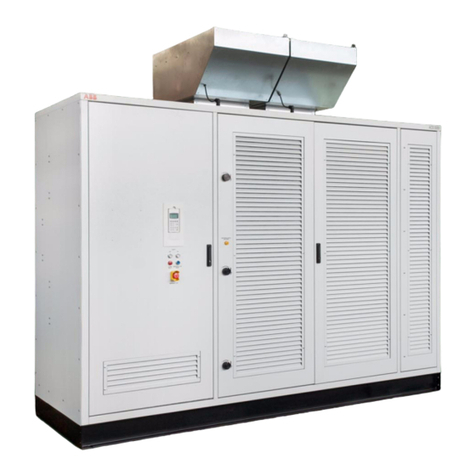
ABB PCS100 AVC-40 User manual

—
2UCD074000E004_G
PCS100 AVC-40
Active Voltage Conditioner
Commissioning Checklist
This Commissioning Checklist is for use by
ABB Certified Engineers holding an Expert
Certificate and applies to PCS100 AVC-40s
with software version R2J4.
All steps in the checklist must be performed
and ticked during commissioning and the
completed document scanned and sent to
the ABB factory.
© Copyright 2020 ABB, All rights reserved.
—
PCS100 AVC-40
300 kVA to 3000 kVA

2PCS100 AVC-40 Commissioning Checklist
—
About This Document
The Company
We are an established world force in the design and manufacturing of power electronics and power protection
equipment.
As part of ABB, a world leader in electrical technology, we offer customers application expertise, service, and
support worldwide.
We are committed to teamwork, high quality manufacturing, advanced technology and unrivalled service and
support.
The quality, accuracy and performance of the Company’s products result from over 100 years’ experience,
combined with a continuous program of innovative design and development to incorporate the latest technology.
Quality Control
The products listed in this catalogue are manufactured in an ISO 9001 accredited facility.
For More Information
Further publications for the PCS100 AVC-40 are available to download for free from
http://new.abb.com/ups/power-and-voltage-conditioners/voltage-conditioners/pcs100-avc-40
Registration No. 2469
https://new.abb.com/ups/

PCS100 AVC-40 Commissioning Checklist 3
—
Document Information
Copyright notice
The information in this manual is subject to change without notice. This manual and parts thereof must not be re-
produced or copied, or disclosed to third parties, nor used for any unauthorized purpose without written permis-
sion from ABB Ltd. The hardware and software described in this manual are provided under a license and may be
used, copied, or disclosed only in accordance with the terms of such license.
Document identification
Ownership: ABB Ltd., Power Conditioning Products
Document number: 2UCD740000E004
Issue date: 13/12/2021
Revision: Rev G
Contact information
Address: ABB Ltd. 111 Main North Road, Napier, New Zealand.
Website: https://new.abb.com/ups
This Document
This document contains information regarding:
–commissioning of the PCS100 AVC-40
Usage
This document should be used when:
–commissioning the PCS100 AVC-40
Who Should Read This Document?
This document is intended for:
–commissioning engineers
Prerequisites
A Commissioning Engineer working with the PCS100 AVC-40 must:
–be trained by ABB and have electrical operational and safety knowledge
–have sufficient training to operate in an accidentally touch safe service environment
–use this document in conjunction with the PCS100 AVC-40 User Manual and PCS100 AVC-40
Installation Checklist and ensure all of the installation checks have been performed prior to
completing this checklist
Software Revision
This document applies to PCS100 AVC-40 systems with software revision R2J4.
https://new.abb.com/ups/

4PCS100 AVC-40 Commissioning Checklist
—
Safety
Safety Instructions
IT
Attenzione: Tensione pericolosa!
Fare riferimento alle istruzioni per l’uso.
Prima di intervenire su questo dispositivo, scollegare e isolare tutte le fonti di
alimentazione.
Attenzione! L’installazione deve essere eseguita esclusivamente da un
installatore qualificato.
LT
Įspėjimas: Pavojinga įtampa!
Žr. naudojimo instrukcijas.
Atjunkite ir laikinai užblokuokite maitinimą prieš dirbdami su šiuo įrenginiu.
Dėmesio! Įrengti gali tik asmuo, turintis elektrotechniko patirties.
AR
! :
.
! .
BG
Предупреждение: Опасно напрежение!
Вижте инструкциите за работа.
Изключете иблокирайте захранването преди да работите сустройството.
Внимание! Да се монтира само от експерт електротехник.
LV
Brīdinājums: Bīstams spriegums!
Skatiet darba norādījumus.
Pirms sākat darbu ar šo ierīci, atvienojiet un bloķējiet strāvas padevi.
Uzmanību! Uzstādīšanu drīkst veikt tikai persona ar zināšanām par
elektrotehniku.
CS
Varování: Nebezpečné napětí!
Viz návod k obsluze.
Před zahájením prací na tomto zařízení odpojte a uzamkněte napájení.
Pozor! Toto zařízení smí instalovat pouze osoba s elektrotechnickou
odborností.
NL
Waarschuwing: Gevaarlijke spanning!
Raadpleeg de bedieningsinstructies.
Koppel dit apparaat los van de stroomvoorziening voordat u werkzaamheden
uitvoert.
Let op! Installatie mag alleen worden uitgevoerd door een monteur met
elektrotechnische expertise.
DA
Advarsel: Farlig elektrisk spænding!
Se betjeningsvejledningen.
Frakobl enheden, og afbryd strømforsyningen, før du arbejder med denne
enhed.
Giv agt! Installation må kun foretages af personer med elektroteknisk
ekspertise.
NO
Advarsel: Farlig spenning!
Se i bruksanvisningen.
Koble fra og steng av strømmen før du arbeider på denne enheten.
Forsiktig! Montering skal kun utføres av kvalifiserte personer med
elektrokompetanse.
DE
Warnung: Gefährliche Spannung!
Siehe Bedienungsanleitung.
Vor dem Arbeiten Gerät ausschalten und von der Spannungsversorgung
trennen.
Achtung! Installation nur durch elektrotechnische Fachkraft.
PL
Ostrzeżenie: Niebezpieczne napięcie!
Patrz: instrukcja obsługi.
Przed rozpoczęciem wykonywania pracy z tym urządzeniem odłącz i zablokuj
zasilanie.
Uwaga! Montaż może wykonywać wyłącznie osoba posiadająca doświadczenie
elektrotechniczne.
EL
Προειδοποίηση: Επικίνδυνη τάση!
Ανατρέξτε στις οδηγίες λειτουργίας.
Αποσυνδέστε και απομονώστε την παροχή ισχύος προτού ξε κινήσετε τις εργασίες σε
αυτήν τη συσκευή.
Προσοχή! Ηεγκατάσταση πρέπει να γίνεται μόνο από αδειούχο ηλεκτρολόγο
εγκαταστάτη.
PT
Aviso: Tensão perigosa!
Consulte as instruções de operação.
Desconecte e desligue a energia elétrica antes de trabalhar nesse dispositivo.
Atenção! A instalação deve ser feita apenas por uma pessoa com
especialidade eletrotécnica.
EN
Warning: Hazardous voltage!
Refer to installation instructions.
Disconnect and lock out power before working on this device.
Attention! Installation by person with electrotechnical expertise only.
RO
Avertisment: Tensiune electrică periculoasă!
Consultați instrucțiunile de utilizare.
Deconectați și închideți sursa de energie înainte de a lucra cu acest
dispozitiv.
Atenție! Instalare
https://new.abb.com/ups/

PCS100 AVC-40 Commissioning Checklist 5
ES
Advertencia: ¡Tensión peligrosa!
Consulte las instrucciones de funcionamiento.
Antes de trabajar con este dispositivo, desconecte y bloquee la corriente.
¡Atención! La instalación debe ser realizada únicamente por un técnico
electricista.
RU
Внимание: Опасное электрическое напряжение!
Обратитесь кинструкциям по эксплуатации.
Отключите питание иобесточьте устройство перед началом работ.
Внимание! Установка должна выполняться только специалистом по
электротехническим работам.
ET
Hoiatus: Elektrilöögi oht!
Lisateavet vaadake kasutusjuhendist.
Enne selle seadmega töötamist ühendage lahti ja lukustage toide.
Tähelepanu! Seadet tohib paigaldada ainult elektrotehnilise kogemusega isik.
SK
Výstraha: Nebezpečné napätie!
Pozrite si návod na použitie.
Pred začatím prác na tomto zariadení odpojte a zablokujte napájanie.
Pozor! Inštaláciu smie vykonávať len osoba s odbornými znalosťami v oblasti
elektrotechniky.
FI
Varoitus: Vaarallinen jännite!
Katso käyttöohje.
Katkaise virta ja estä virran kytkeminen lukituksella ennen töiden aloittamista.
Huomio! Asennuksen saa suorittaa vain henkilö, jolla on kokemusta
sähkötekniikasta.
SL
Opozorilo: Nevarna napetost!
Glejte navodila za uporabo.
Pred delom na tej napravi izklopite in zaklenite električno napajanje.
Pozor! Namestitev sme izvesti samo elektrotehnični strokovnjak.
FR
Avertissement: Tension dangereuse!
Consultez les consignes d’utilisation.
Débranchez et verrouillez l’alimentation électrique avant d’entreprendre des
travaux sur cet appareil.
Attention! L’installation doit être effectuée uniquement par une personne
ayant une expertise en électrotechnique.
SV
Varning: Livsfarlig spänning!
Se i bruksanvisningen.
Frånkoppla och blockera anläggning eller en anläggningsdel innan arbeite
utförs.
Obs! Får endast installeras av behörig elektriker.
HR
Upozorenje: Opasan napon!
Pogledajte upute za uporabu.
Odspojite i isključite struju prije rada na ovom uređaju.
Pažnja! Ugradnja je dopuštena samo osobama stručnim u području
elektrotehnike.
TR
Uyarı: Tehlikeli gerilim!
Çalışma talimatlarına bakın.
Bu cihaz üzerinde çalışmadan önce elektriği kesin ve kilitleyin.
Dikkat! Yalnızca elektroteknik uzmanlığa sahip kişiler tarafından kurulabilir.
HU
Figyelmeztetés: Veszélyes feszültség!
Lásd a használati utasítást.
Válassza le és zárja ki az áramellátást, mielőtt a berendezésen dolgozni kezd.
Figyelem! Az üzembe helyezést csak elektrotechnikai szakértelemmel
rendelkező személy végezheti el.
ZH
警告:高压危险!
请参见操作手册
操作本设备前请断开并锁定电源。
注意!安装仅限专业电工人员。

6PCS100 AVC-40 Commissioning Checklist
—
Safety Notices
This checklist contains important information regarding the operation of the ABB’s PCS100 AVC-40 This checklist
provides technical and operational guidance for commissioning engineers. The following safety instructions are
to be observed.
DANGER
This checklist does not provide sufficient information for safe service of the PCS100 AVC-40.
For such service information refer to appropriate manual.
CAUTION –Trained Commissioning Engineers
All operations on the PCS100 AVC-40 must only be carried out by a trained commissioning
engineer familiar with the contents of this checklist. Hazardous conditions could arise from
incorrect adjustment.
DANGER –Stored Charge
Stored charge is present after the device is switched off.
DANGER –Protective Covers
Normal operation of this product requires any protective covers in place and doors secured
closed.
DANGER –Personal Protection Equipment
Ensure safety glasses are worn while working if any part of the unit could be energized.
https://new.abb.com/ups/

PCS100 AVC-40 Commissioning Checklist 7
—
Contents
About This Document......................................................................................................................................................... 2
The Company............................................................................................................................................................................................................ 2
Quality Control ......................................................................................................................................................................................................... 2
For More Information ............................................................................................................................................................................................. 2
Document Information........................................................................................................................................................................................... 3
This Document ......................................................................................................................................................................................................... 3
Usage.......................................................................................................................................................................................................................... 3
Who Should Read This Document?...................................................................................................................................................................... 3
Prerequisites............................................................................................................................................................................................................. 3
Software Revision.................................................................................................................................................................................................... 3
Safety 4
Safety Instructions.................................................................................................................................................................................................. 4
Safety Notices .......................................................................................................................................................................................................... 6
Commissioning Checklist ..................................................................................................................................................8
1.1 Pre-Power Visual Checks.............................................................................................................................................................................. 8
1.2 DIP Switch Settings .................................................................................................................................................................................... 10
1.3 Power Connection Checks..........................................................................................................................................................................12
1.4 Earth (Ground) Checks................................................................................................................................................................................13
1.5 Change Frequency from 50Hz to 60Hz (if required)............................................................................................................................ 14
1.6 Initial Power Up –Utility Supply ............................................................................................................................................................... 14
1.7 Stop –Enable Switch Test......................................................................................................................................................................... 16
1.8 Initial Run –No Load................................................................................................................................................................................... 16
1.9 External Transformer Wiring Check –No Load......................................................................................................................................17
1.10 External Transformer Thermal Test (Optional) .....................................................................................................................................17
1.11 Load Test ...................................................................................................................................................................................................... 18
1.12 Documentation and Handover ................................................................................................................................................................. 18
1.13 PCS100 AVC-40 Settings ........................................................................................................................................................................... 19
1.14 Deviations .....................................................................................................................................................................................................20
1.15 Sign-Off .........................................................................................................................................................................................................20
https://new.abb.com/ups/

8PCS100 AVC-40 Commissioning Checklist
—
Commissioning Checklist
The following commissioning checklist for the PCS100 AVC-40 is required to be completed and signed off by a
suitably qualified engineer who has been trained in the use of power systems, electrical safety and the PCS100
AVC-40 products.
Company:
Site:
Plant:
PCS100 AVC-40 Model:
PCS100 AVC-40Serial Number:
Engineer:
Date:
Before proceeding with this commissioning schedule, the Commissioning Engineer should be familiar with the
following:
–accessing and navigating within the menu, including the commissioning section, on the GDM
–adjusting system parameters on the GDM
–starting and stopping the PCS100 AVC-40 via the GDM
1.1 Pre-Power Visual Checks
No
Description
Check
1.
Check power to the unit is safely isolated and locked off.
2.
Confirm power is isolated with a meter check.
3.
Visual check mechanical installation.
4.
Check there is no physical damage to unit and internal parts.
5.
Check no debris, swarf or wire strands are present.
6.
Check there is no insulation damage or signs of exposure to water or conductive dust
during transport and storage.
7.
Check the clearances between terminals, cables, bolts, and lugs are appropriate.
Ideally the main supply and load power terminations at the transformer should be fully
insulated.
8.
Check the supply and load cable or buswork used is adequate for PCS100 AVC-40 load
rating.
9.
Check all rectifier and inverter modules are correctly connected to the power wiring
and the communications and control ribbon cable is fully bedded.

PCS100 AVC-40 Commissioning Checklist 9
10.
Check the Auxiliary Master Module is correctly connected to the power wiring and the
communications ribbon cable is fully bedded.
11.
Check the GDM is correctly connected to the power wiring and the communications
ribbon cable is fully bedded.
12.
Check there is no cooling air path blockage at front and rear (at least 200mm) of the
Controller Enclosure
13.
Check the environment is suitable for the PCS100 AVC-40’s IP20 rating, i.e. water or
excessive dust is not able to enter the PCS100 AVC-40 enclosures.
14.
Check fuses:
F1 12A Auxiliary Master Module
F2 12A Auxiliary Master Module
F3 Auxiliary Master Module –NOT USED
F8 6A Auxiliary Master Module
F4/F5 20A located in the Transformer Enclosure for large systems.
Transformer enclosure Circuit Breaker: check short circuit protection I3 (magnetic)
setting is as per the current listed in the following table. Note: if the CB does not have
the exact I3 current setting shown in the table, then the CB I3 should be set to the next
higher setting.
Overload protection (thermal) by the CB is not required as it is provided by the
inverters. If the CB has overload protection set it to maximum.

10 PCS100 AVC-40 Commissioning Checklist
1.2 DIP Switch Settings
Check the DIP switch settings of the various components within the system if they have been replaced or have
changed prior to commissioning. Note these switches are all set at the Factory as part of the production test
process.
Note:
The following pictures may not represent actual settings for this unit, refer to the appropriate table.
No
Description
Check
15.
Check the DIP switch settings on the CAN Termination Board.
The CAN Termination Board is mounted on the right hand side of the Master
Controller Enclosure.
SW1 (bottom) has DIP switches 3-5 set to OFF. Switches 1,2 and 8 are set to ON.
Switches 6,7 can be set to ON or OFF.
* SW2 (top) is not used therefore DIP switches can be set ON or OFF
SW3 (middle) has DIP switches 1 & 2 set to OFF and 3 & 4 set to ON.
Text…
SW2
1 ANY
2 ANY
3 ANY
4 ANY
SW3
1 OFF
2 OFF
3 ON
4 ON
SW1
1 ON
2 ON
3 OFF
4 OFF
5 OFF
6 ANY
7 ANY
8 ON
*

PCS100 AVC-40 Commissioning Checklist 11
No
Description
Check
16.
Check the DIP switch settings on the Current Sense Board.
Current Sense Board
The Current sense board is mounted in the Transformer Enclosure, on or near the circuit
breaker panel. It has three sets of DIP switches. All DIP switches, SW1, SW2 & SW3 on the
current sense board are set for the current rating of the unit. These settings are set in
the
Factory and should not need to be adjusted. If any settings are found to be different
from these settings stated below, please contact the factory.
Power Rating (kVA)
Pole
SW3
SW2
SW1
300
1
On
On
On
2
Off
Off
Off
3
Off
Off
Off
4
Not Used
600
1
On
On
On
2
On
On
On
3
Off
Off
Off
4
Not Used
750
1
On
On
On
2
Off
Off
Off
3
On
On
On
4
Not Used
900
1
On
On
On
2
On
On
On
3
On
On
On
4
Not Used
SW3 SW2 SW1

12 PCS100 AVC-40 Commissioning Checklist
No
Description
Check
Power Modules
Pole
SW3
SW2
SW1
1200, 1500
1
On
On
On
2
Off
Off
Off
3
On
On
On
4
Not Used
1800
1
On
On
On
2
On
On
On
3
On
On
On
4
Not Used
2400, 3000
1
On
On
On
2
Off
Off
Off
3
On
On
On
4
Not Used
3600
1
On
On
On
2
On
On
On
3
On
On
On
4
Not Used
1.3 Power Connection Checks
No
Description
Check
17.
Check all power connections are assembled and tightened correctly; check power
terminations have been fully insulated
18.
Perform a point-to-point wiring check as per installation wiring diagram to determine
the transformer is correctly connected and phased.
19.
Open MCCB (if fitted) and F4/F5 20A auxiliary fuses. Using a simple ohm-meter check
there is no short circuit PCS100 AVC-40 input to input (L1–L2, L2–L3, L3–L1) (load
disconnected and input circuit breaker open).
20.
Perform this step only with the 400/480V PCS100 AVC-40 (these are the models that
do not have an autotransformer) fitted with a MCCB (rectifier circuit breaker). Open
the rectifier feed MCCB and F4/F5 20A auxiliary in the MC Enclosure. Check for
continuity L1-L2, L2-L3 and L3-L1 on the downstream side (rectifier side) of the MCCB.
This must show an open circuit. Close F4/F5 fuses.
21.
Using the resistance range of a multimeter, check there is no short circuit at PCS100
AVC-40 input to ground (L1-G, L2-G, L3-G).
22.
Using the resistance range of a multimeter, check there is no short circuit at rectifier
supply input to ground (L1R-G, L2R-G, L3R-G.).

PCS100 AVC-40 Commissioning Checklist 13
23.
Check for continuity between injection transformer A2, B2, C2 and the PCS100 AVC-40
Inverter module AC terminals, U, V, W. This will require either removing the module covers,
or inserting a digital multi meter/duspol probe under the module front cover on the
PCS100 Inverter module.
NB: PCS100 Inverter modules on the PCS100 AVC-40 2B and larger machines are
always on the upper shelf of the Controller Enclosure.
PCS100 Inverter modules
24.
Check there is no short circuit at inverter output to ground (Inv L1-G, Inv L2-G, Inv L3-
G).
25.
Confirm the auxiliary supply cable is connected to the correct terminals located under
the rectifier shelf next to the L1R terminal of all Controller Enclosures. The label at the
bottom of each Controller Enclosure shows the correct connections depending on the
AVC system voltage.
1.4 Earth (Ground) Checks
No
Description
Check
26.
Check the PCS100 AVC-40 is earthed to the utility supply at the main Earth Stud.
27.
Check the internal earth to the PCS100 AVC-40 Enclosure (PE).
28.
Check the internal earth to the Injection Transformer (TE).

14 PCS100 AVC-40 Commissioning Checklist
1.5 Change Frequency from 50Hz to 60Hz (if required)
If the PCS100 AVC-40 needs to be changed from a 50Hz to a 60Hz machine.
No
Description
Check
29.
Unplug the DB9 cable to the Auxiliary Master Module from VR1 and VR2
30.
This is not applicable to all models as some MCCBs do not have frequency settings.
Check the switch settings on the MCCB and if there is a frequency setting adjust this
to the 60Hz setting. Do not adjust any other settings on the MCCB.
31.
Perform the power up procedure as described in Section 1.6. up to step 42.
32.
Power down the PCS100 AVC-40 and reconnect VR1 and VR2 to the Auxiliary Master
Module.
33.
Turn power on again to the PCS100 AVC-40 and continue from step 43.
1.6 Initial Power Up –Utility Supply
All loads should remain disconnected at this stage.
No
Description
Check
34.
Check all protective covers are in place.
35.
Ensure the Stop –Enable switch is set to Stop.
36.
Apply utility power to the PCS100 AVC-40 and verify the system has energised
correctly.
37.
Verify the red LED on top of the Auxiliary Master Module and any Auxiliary Slave Module
is on. This indicates the 26.5 volts DC power supply is operational.
38.
Once the automatic start-up and configuration check has been performed verify the
blue LED on top of the master module is flashing. This indicates the DSPE micro is
running
39.
Verify the inverter and rectifier modules power up correctly by checking the module
display board status LEDs. Refer to the PCS100 AVC-40 User Manual for descriptions
of these LEDs. The OK LEDs should be on and the run LEDs should be off. Check the
module identification numbers are unique. Resolve any abnormal condition before
continuing with this checklist. L0 remaining on the module display boards indicates a
fatal error in the System Configuration Manager (SCM). The exact error code will be
signaled by the flashing LED on the SCM board. (Refer to ABB document no
2UCD200000E430 SCM diagnostics
).
40.
Verify the GDM powers up, if not confirm the GDM is turned on by pressing the small
button on the GDM rear panel (left hand end). It will initially show default start-up
screens.
Successful configuration check will be indicated by the GDM displaying the Status
Page, and no configuration errors being reported.
The GDM control panel should show ‘Inhibit’ indicating the system is inhibited from
starting by the Stop –Enable switch. The GDM should show Status: BYPASS indicating
the bypass condition of the unit.
41.
On the GDM, access the Menu page and select 00 Password and enter the correct Tech
password to change to the Tech menu

PCS100 AVC-40 Commissioning Checklist 15
42.
Check 13 Supply Voltage and 14 Supply Frequency are correct for the application.
Adjust if necessary.
43.
Check 12 Transformer Config is set correctly for the application.
This parameter is set by default to “Top Input”, but if the transformer wiring was
changed for “Bottom Input” (contact the Factory for the procedure to perform this
change), then this parameter must be checked and changed accordingly to “Bottom
Input”.
44.
Check 600 V Set Manual setting is correct for the application. Adjust if necessary.
45.
Check 601 V Set Source is set to MANUAL.
46.
Check the Customer’s requirements and set 27 Auto Start and A63 SSH Port Enable
accordingly.
47.
If any faults are present and reported on the display then resolve these faults before
continuing.
48.
If Modbus TCP or remote webpages are to be used adjust the network configuration
parameters B11 to B14.
49.
Enter the company, site and plant via parameters 02, 03 and 04. (Entering the Operator
or Tech password is required).
50.
Verify the Input Voltage and Output Voltage (and Frequency if possible) measurements
shown on the GDM status screen are correct with a true RMS meter.
51.
Verify all the rectifier, inverter module fans are running and exhausting correctly (check
air flow at rear).
52.
Verify all transformer fans (if applicable) are running correctly.
53.
Check the GDM s/w revision is up to date using the GDM Software Upgrade Tool.
54.
Power down the PCS100 AVC-40.
55.
Set the Stop –Enable switch to Enable.
56.
Ensure the doors are closed and then re-power the PCS100 AVC and allow the
configuration check to complete. Following this verify the INHIBIT is now removed
from the Status Bar on the GDM.

16 PCS100 AVC-40 Commissioning Checklist
1.7 Stop –Enable Switch Test
This stage verifies correct function of the Stop – Enable switch.
No
Description
Check
57.
Start the PCS100 AVC-40 Verify the PCS100 AVC-40 UL enters RUN mode, and no
faults exist.
58.
Turn the Stop - Enable switch to Stop to bypass the PCS100 AVC-40. Verify the
PCS100 AVC-40 enters BYPASS mode, and no faults exist. INHIBIT will be shown on
the GDM.
59.
Return the Stop - Enable switch to Enable. Verify the PCS100 AVC-40 remains in
BYPASS mode. INHIBIT will be removed from the display.
1.8 Initial Run –No Load
This stage verifies correct function of the inverter.
No
Description
Check
60.
Start the PCS100 AVC-40. Verify the PCS100 AVC-40 enters RUN mode, and no faults
exist.
61.
Stop the PCS100 AVC-40. Verify the PCS100 AVC-40 returns to the BYPASS mode and
no faults exist.
62.
Access the menu and change 600 V Set Manual to 105% of the nominal supply voltage
and start the PCS100 AVC-40. The PCS100 AVC-40 will correct the output voltage to
105% of nominal supply voltage.
Verify the GDM Output Voltage measurements show 105% of nominal supply voltage
on the status page, and that no faults exist.
63.
Stop the PCS100 AVC-40. Verify the PCS100 AVC-40 returns to BYPASS and set 600 V
Set Manual back to 100% of the nominal supply voltage or set to needed level.

PCS100 AVC-40 Commissioning Checklist 17
1.9 External Transformer Wiring Check –No Load
This test only needs to be performed on the PCS100 AVC-40s constructed with separate Controller and
Transformer Enclosures. It is not necessary for small PCS100 AVC-40s with a single enclosure.
Note: This test will add up to 10% over-voltage at the output of the PCS100 AVC-40.
No
Description
Check
64.
Set 20 Configuration Check Mode to “true” in the COMMISSIONING menu and Start
the PCS100 AVC-40. This will correct the output voltages V1 to 100%, V2 to 105% and
V3 to 110% of 13 Supply Voltage setting.
Note : V1 = V L1’L2’, V2 = V L2’L3’, V3 = V L3’L1’
65.
Scroll to the status page of the GDM and verify the displayed output voltage V1, V2
and V3 is within 1% of the values in step 62. This verifies the transformer is wired
correctly and ratios are correct.
Stop the PCS100 AVC-40 and then set 20 Configuration Check Mode back to “false”.
66.
If the output voltages V1, V2 and V3 are not within 1% of the values in step 62 then
recheck transformer connections as per the wiring diagram. Repeat the steps above
when PCS100 AVC-40 is re-powered.
1.10 External Transformer Thermal Test (Optional)
This test is not required for normal commissioning. This is a special test which permits a full current thermal test
for the transformer. It should only be performed if there is special requirement to check the transformer and in
consultation with the factory. Standard units are type tested and do not require this test. It requires an external
bypass circuit.
No
Description
Check
67.
Ensure bypass switch S1, S2, S3 are closed, and the load isolator switch is open or the
load turned off.
68.
Ensure the load is turned off. Power up the PCS100 AVC-40 if not already powered up.
Log in on the GDM using the Tech Access password.
69.
Set 21 Test Mode to OUTWAVEPLL. Start the PCS100 AVC-40. Increase 22 Test
Voltage until the load current on the GDM status screen equals approximately 95%. At
this time full rated load current will be flowing through the short circuit on the supply
side of the Injection Transformer created by switches S1, S2 and S3 as shown in Figure
0-1. Allow temperatures to stabilise (will take several hours) and check the
transformer, switch, and cable connection temperatures are not excessive.
PCS100
AVC-40
Supply Load
Input
Isolator Output
Isolator
Bypass
S2 S3
S1
Current flow
Figure 0-1: PCS100 AVC-40 with external bypass circuit
70.
At the end of this test stop the PCS100 AVC-40. Set 21 Test Mode to NONE and 22
Test Voltage to 0V.

18 PCS100 AVC-40 Commissioning Checklist
1.11Load Test
No
Description
Check
71.
Switch the load on.
Start the PCS100 AVC-40. Verify the PCS100 AVC-40 enters RUN mode and no faults
exist.
72.
Check the voltages on the GDM status screen are as expected. The output voltage
should be ~ 100% of the 600 V Set Manual value.
73.
Check the load currents on the GDM status screen match the actual measured load
currents within tolerance. Ensure greater than 5% load current is applied for this
check.
74.
Check the loading level < 100% on GDM status screen.
75.
Check no overload is shown on the GDM unless greater than 10% voltage correction
is being provided.
1.12 Documentation and Handover
No
Description
Check
76.
Connect a PC to the PCS100 AVC-40 via the GDM USB and run a web browser on the
PC. Download and save the Service Log for future use or reference. See document
2UCD200000E001 How to View the GDM Remote Web Pages for detailed instructions.
77.
In the PCS100 AVC-40 Settings below record the settings that have been changed
78.
Ensure the correct user documentation or manuals are available within the system, or
accessible by staff.
79.
Place or store other documentation at appropriate locations.
80.
Provide training to appropriate staff.
81.
Ensure plant staff knows the system is now in service.
82.
A copy of this checklist and the Service Log must be sent to ABB Power Conditioning
Products or emailed to nz-powerconditioningservice@abb.com. Failure to comply
with this may affect any possible future warranty claims.

PCS100 AVC-40 Commissioning Checklist 19
1.13 PCS100 AVC-40 Settings
Menu number & name
Parameter number & name
Value
0
General
02
Customer Name
03
Plant Name
04
Site Name
1
System Electrical
10
System Current
11
Rectifier Voltage
12
Transformer Config
13
Supply Voltage
14
Supply Frequency
15
Sag Threshold
16
Surge Threshold
6
References
600
V Set Manual
GDM A00
Display
A31
GDM Control Enable
GDM B00
Network Settings
B11
Dynamic IP DHCP
B12
Static IP address
B13
Static IP mask
B14
Static IP gateway

20 PCS100 AVC-40 Commissioning Checklist
1.14 Deviations
List any outstanding issues in the space below.
No
Description
1.
2.
4.
5.
6.
7.
8.
9.
10.
1.15 Sign-Off
Party
Name
Date
Customer
Name (please print):
Signature:
Commissioning
Engineer
Name (please print):
Signature:
Table of contents
Other ABB Air Conditioner manuals