LED CONTROLLER
PRI:
Uin=12-36VDC
Iin=32.5A
SEC:
Uout=4x(12-36)VDC
Iout=4x8A
Pout=4x(96-288)W
TEMP RANGE:-20℃-+50℃
19006-01
V+
G-
R-
OUTPUT SI GN AL
CH1
2
DC INPUT
12/ 36V DC
V+
V-
B-
3
B-
3
W-
4
Lea rn in g
Swi tc h
LED CONTROLLER
PRI:
Uin=12-36VDC
Iin=32.5A
SEC:
Uout=4x(12-36)VDC
Iout=4x8A
Pout=4x(96-288)W
TEMP RANGE:-20℃-+50℃
19006-01
V+
G-
R-
OUTPUT SI GN AL
CH1
2
DC INPUT
12/ 36V DC
V+
V-
B-
3
B-
3
W-
4
Lea rn in g
Swi tc h
LED CONTROLLER
PRI:
Uin=12-36VDC
Iin=32.5A
SEC:
Uout=4x(12-36)VDC
Iout=4x8A
Pout=4x(96-288)W
TEMP RANGE:-20℃-+50℃
19006-01
V+
G-
R-
OUTPUT SI GN AL
CH1
2
DC INPUT
12/ 36V DC
V+
V-
B-
3
B-
3
W-
4
Lea rn in g
Swi tc h
LED CONTROLLER
PRI:
Uin=12-36VDC
Iin=32.5A
SEC:
Uout=4x(12-36)VDC
Iout=4x8A
Pout=4x(96-288)W
TEMP RANGE:-20℃-+50℃
19006-01
V+
G-
R-
OUTPUT SI GN AL
CH1
2
DC INPUT
12/ 36V DC
V+
V-
B-
3
B-
3
W-
4
Lea rn in g
Swi tc h
LED CONTROLLER
PRI:
Uin=12-36VDC
Iin=32.5A
SEC:
Uout=4x(12-36)VDC
Iout=4x8A
Pout=4x(96-288)W
TEMP RANGE:-20℃-+50℃
19006-01
V+
G-
R-
OUTPUT SI GN AL
CH1
2
DC INPUT
12/ 36V DC
V+
V-
B-
3
B-
3
W-
4
Lea rn in g
Swi tc h
Universal series RF Receiver
Input
Voltage
Output
Current
12-36VDC 4x(96-288)W
4x8A
Output
Power
Waterproof grade: IP20
Radio Frequency : 869.5/916.5/434mhz
Function introduction
Product Data
• DO NOT expose the device to moisture.
• DO NOT install with power applied to device.
Safety & Warnings
LED CONTROLLER
PRI:
Uin=12-36VDC
Iin=32.5A
SEC:
Uout=4x(12-36)VDC
Iout=4x8A
Pout=4x(96-288)W
TEMP RANGE:-20℃-+50℃
19006-01
V+
G-
R-
OUTPUT SIGNAL
CH1
2
DC INPUT
12/3 6VDC
V+
V-
B-
3
B-
3
W-
4
Learning
Switch
Learning Key:
Paring with RF remote
DC Power input
CH 1:R/WW output(-)
CH 2:G/CW output(-)
CH 3:B/WW output(-)
Common Anode Output(+)
Master/Slave
jumper
CH 4:W/CW output(-)
Important: Read All Instructions Prior to Installation
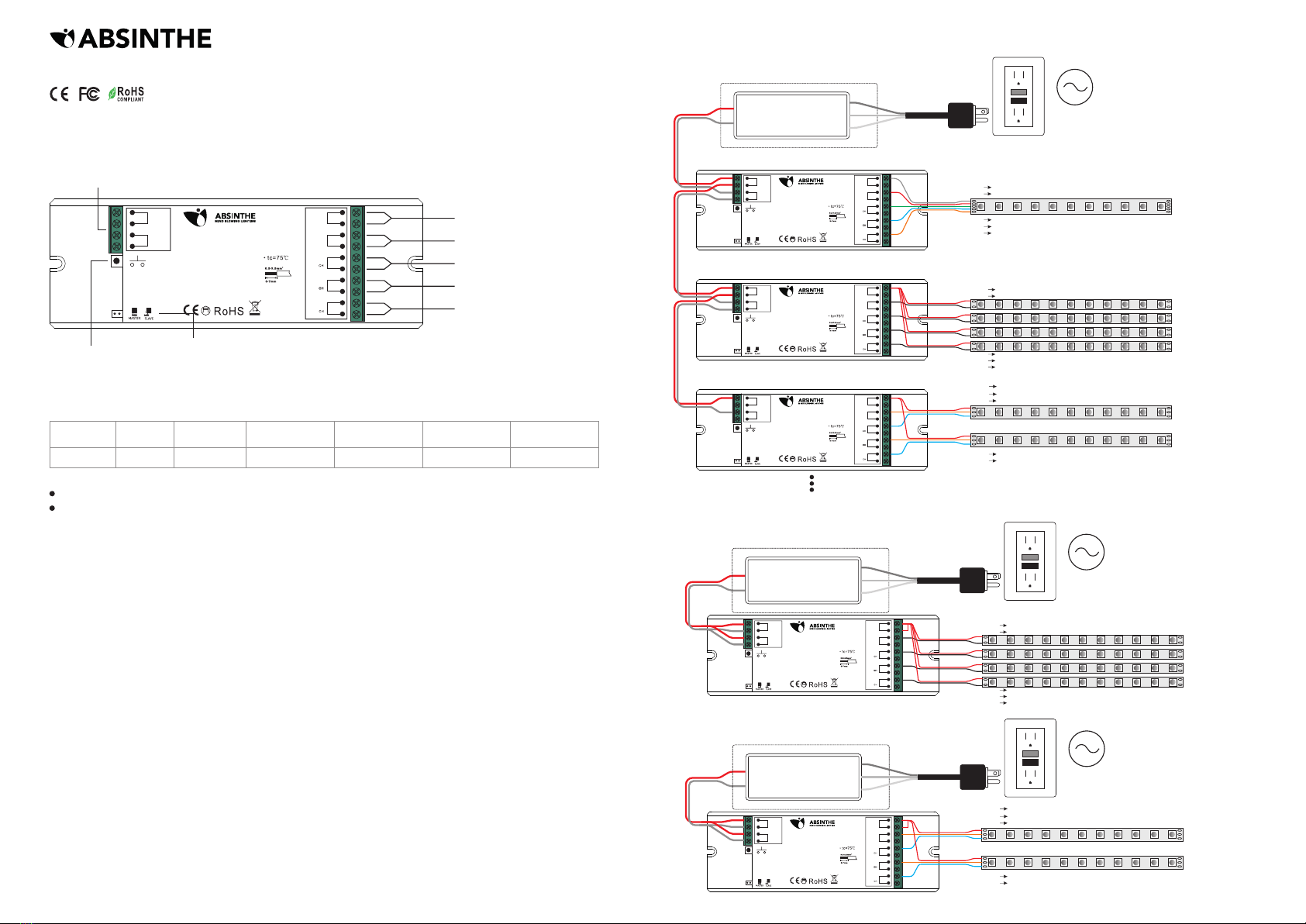
Wiring Diagram
L
N
G
V+
V-
OUTPUT
INPUT
AC Power
50/60Hz
12V/24V/36V
CV PSU
If Con nect wi th RGBW L ED S trip
V+ V+
R- R-
G- G-
B- B-
W- W-
V+ V+
1- V-
2- V-
3- V-
4- V-
If Con nect wi th Sing le C olor LE D Strip
V+ V+
WW WW
CW CW
WW WW
CW CW
If Con nect wi th Dual C ol or LED St rip
1. The receiver has both master and slave functions which can be set with a jumper. Short circuit of the jumper
means master function, and open circuit means slave function. Once short circuit the jumper on a receiver,
please power off and power on the receiver to enable master function. Setting master and slave enables perfect
synchronization of color changing effects.
2. Set one receiver as master and pair it to any zone of a remote, and this zone shall only have one receiver
which works as master. Set all other receivers as slave and pair them to other zones of the remote, and multiple
receivers can be paired to each zone. Then choose all zones on the remote and play the color changing
effects, the master will send sync signal to the slaves to achieve perfect synchronization. The max. sync
distance between the master and any slave is within 30m.
Master and Slave Setting:
Pair/delete the pairing with RF remote
2.Pair RF Receiver with RF remote: please refer to the instruction of the remote that you would like to pair with.
3.Delete the pairing:
(1)Wire up the RF receiver correctly, power on.
(2)Press and hold down the “ Learning Key” button on receiver for over 3 seconds until the connected light
flashes, which means well deleted.
1.Do wiring according to connection diagram.
Remarks
Constant voltage
Size(LxWxH)
170x59x29mm
1) When total load of each receiver is not over 20A
2) When total load of each receiver is over 20A
V+ V-
L
N
G
V+
V-
OUTPUT
INPUT
AC Power
50/60Hz
12V/24V/36V
CV PSU
V+ V+
1- V-
2- V-
3- V-
4- V-
If con nect wi th Sing le C olor LE D
V+ V-
L
N
G
V+
V-
OUTPUT
INPUT
AC Power
50/60Hz
12V/24V/36V
CV PSU
V+ V+
WW WW
CW CW
WW WW
CW CW
If con nect wi th Dual C ol or LED
Max. 20A
2
0.05-3.3mm
(12-30AWG)
Connector
Current Rating Wire Size
19006-01


