Absolute ABS-1500 User manual

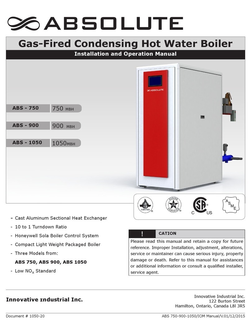
Gas-Fired Condensing Hot Water Boiler
Installation and Operating Manual
Innovative Industrial Inc.
ABS 1500-2000-2500-3000-4000/V.01/4/2016
ABS - 1500
ABS - 2000
ABS - 2500
ABS - 3000
ABS - 4000
CAUTION
Please read this manual and retain a copy for future
reference. Improper Installation, adjustment, alterations,
service or maintainer can cause serious injury, property
damage or death. Refer to this manual for assistances
or additional information or consult a qualied installer,
service agent.
Innovative Industrial Inc.
122 Burton Street
Hamilton, Ontario, Canada L8l 3R5
-Cast Aluminum Sectional Heat Exchanger
- 10 to 1 Turndown
- Honeywell Sola Boiler Control System
- Compact Light Weight Packaged Boiler
- Five Models from 1,500 to 4,000 MBH
- Low NOxStandard
- Fully Packaged CSA/ASME Boilers
Document # 2050-20

Absolute Boilers ABS 1500-2000-2500-3000-4000
2
CATION
Before you install and operate this boiler, please read this manual carefully in its entirety. If for whatever reason you
are not clear of any details, please do not hesitate to contact us as shown below. Please read all safety and warnings
symbols. The installation and service manual is part of the documentation along with the boiler. The installer is to
explain the function of the boiler and heating system, before the boiler goes into full service.
For service or parts, contact your local sales representative.
Notice: In the interests of technical progress, the information in this installation and service manual is subject to change without
prior notice from Innovative Industrial Inc.

Absolute Boilers ABS 1500-2000-2500-3000-4000
3
Contents
1. SAFETY INSTRUCTIONS 6
1.2 Symbols 6
1.2 General safety notes 7
1.3 Lighting Instructions 8
2.2 Operational principal of boiler 11
2.3 View of boiler for service connections 11
3. Technical Data 12
3.1 Boiler Version 13
3.2 Technical Data Sheet 15
3.3 Absolute Boiler Specications: 16
3.4 Ordering options: 17
3.5 Pressure relief valve requirements 17
4. Installation: 18
4.1. General installation Instructions 18
4.2. Delivery and installation 18
4.2.1 Site preparation 19
4.2.2 Hoisting the boiler 19
4.2.3 Multiply boiler arrangements 20
4.3 Flue gas discharge and air supply 22
4.3.1 General 22
4.4 Boiler Venting Types 22
4.4.1 Venting options 23
4.4.2 Vent Termination Inlet/Outlets 23
4.4.3 Combustion Air Supply Requirements 23
4.4.4 Room combustion air supply requirements: 24
4.4.5 Conventional vent system clearances 24
4.4.6 Co-venting – Retrotting: 27
4.4.7 Vent terminations installation precautions: 29

Absolute Boilers ABS 1500-2000-2500-3000-4000
4
4.5 Condensate drain connection and trap 30
4.6 Water connection 31
4.6.1 Water pressure 32
4.6.2 Safety valve 32
4.6.3 Water treatment 33
4.6.4 Water Flow 34
4.6.5 Typical water system layout 35
4.6.6 Frost Protection 36
5. Electrical 36
5.1 General 36
5.2 Main power voltage 36
5.2.1 Sola Model R7910A-1027 37
5.2.2 Honeywell Sola R7910A 1027 control (sheet 1-12) 37
5.3 Power consumption 53
5.4 Limit Controls 53
5.4.1 Temperature control 53
5.4.2 Low water level protection (LWCO) (ow and content) 53
5.4.3 High limit protection 53
5.4.4 Air pressure switch 53
5.4.5 High gas pressure switch (HGP) 54
5.4.6 Low gas pressure switch (LGP) 54
6 Gas connection 55
6.1 Gas connection 55
6.1.2 Manual gas valve upstream of boiler (The manual valves supplied by others) 55
6.1.3 Gas line piping to boiler 56
6.2 Gas pressures 56
6.3 Gas / air ratio control 57
6.4 Gas valve adjustment 57
7. Commissioning: 60
7.1 Pre operational checks 60
7.2 Safety and lighting instructions 60
7.3 Combustion setting and adjustment 61

Absolute Boilers ABS 1500-2000-2500-3000-4000
5
8. Operator Interface Display 63
8.1 Honeywell Sola Control Programming/Conguration 64
8.2 Programming Access: 64
9. COMMISSIONING 66
9.1 Pre operational checks 66
9.2 Safety checks and lighting instructions 66
9.3 Commissioning Steps 67
9.4 IMPORTANT SAFETY WARNING: 69
10 Commission report 72
10.1 Installation and Location details 72
11 Maintenance 73
11.1 General Maintenance 73
11.1.1 Inspection of air box and dirt trap 73
11.1.2 Cleaning the Whirlwind 73
11.1.3 Cleaning the fan 74
11.1.4 Cleaning the heat exchanger 74
11.1.5 Cleaning the burner assembly 75
11.1.6 Cleaning the siphon 75
11.1.7 Cleaning/replacing the ignition/ionization rod 76
11.1.8 Filter maintenace and lter replacement 76
11.1.9 Sight glass cleaning 77


Absolute Boilers ABS 1500-2000-2500-3000-4000
7
1. SAFETY INSTRUCTIONS
1.2 Symbols
The following symbols are used in this document to emphasize certain instructions. This is in order to increase your
personal safety and to safeguard the technical reliability of the boiler.
CAUTION Indicates a potentially hazardous situation which, if ignored, may result in minor injury or product/
property damage.
WARNING Indicates a potentially hazardous situation which, if ignored, can result in danger, serious injury or
substantial product/property damage.
DANGER
Indicates the presence of a hazardous situation which, if ignored, will result in death, serious injury
or substantial product/property damage.
READ
Indicates recommendations made by EnerPro Boilers for the installers which help to ensure optimum
operation and longevity of the equipment.
Professional licensed heating
contractor
The assembly, installation, adjustment,
service and maintenance of this boiler must
be performed by a professional licensed
heating contractor.
Boiler Documentation
Make sure to read all documentation related
to the product before starting the installation.
The product documentation should be stored
near the boiler where it can be accessed
for future reference.
Advice for the owner
When the installation has been
completed, the heating contractor has to
familiarize the operator/owner with the
installed equipment as well as any safety
precautions and requirements, and shut-
down procedures. The heating contractor
also needs to inform the operator/owner
of the need for professional annual
servicing of the boiler prior to the heating
season.
Contaminated air
Chemicals can contaminate the air and
cause by-products during the combustion
process. These by-products are poisonous
to the occupants and very destructive to
EnerPro boilers.
Carbon monoxide
Flue products can ow into living spaces if
improperly installed, adjusted, serviced or
maintained. The ue gases contain carbon
monoxide which is poisonous.
Fresh air
Adequate ventilation and combustion air
must be provided for the equipment as it
requires fresh air for safe operation. Make
sure the equipment is installed ensuring
an adequate supply of fresh air.
Boiler venting
Always operate the boiler with an installed
vent system. Carbon monoxide poisoning
can be caused by an improperly installed
vent system. All combustion products must
be vented safely to the outdoors.
i
Some products may not be exactly as illustrated.
Information contained herein is deemed as accurate
as possible. Clarication of material supply, pipe
sizing, thread type, and typographical errors
should be noted as soon as possible. Dimensions
have been converted from the Metric standard.
Fractional rounding may aect dimensional
tolerances.
Warranty
The information in this manual and any other related
manuals must be read and proper procedures followed.
The warranty is rendered null and void if the procedures
are not followed as prescribed.

Absolute Boilers ABS 1500-2000-2500-3000-4000
8
1.2 General safety notes
Installers and operational personnel must at all times observe all safety regulations. The following warnings and cautions
are general and must be given the same attention as specic precautions included in these instructions.
The installation must conform to the requirements of their authority having jurisdiction or, in the absences of such
requirements, with the National Fuel Gas Code ANSI Z223.1/NFPA 54 and /or Natural Gas and Propane Installation
Code, CAN/CSA B149.1
Where required by the authority having jurisdiction, the installation must conform to the Standards for Control and
Safety Devices for Automatically Fired Boiler, ANSI/ASME CSD1
Product is CSD-1 complaint. Authorities having jurisdiction should be contacted before installations begin.
DANGER
Flue gas products contain carbon monoxide gas
which can cause nausea or asphyxiation, resulting
in severe personnel injury or death!
WARNING
The boiler is connected to 120 VAC 1ph and/or 230 VAC
3 ph. An improper installation or attempts to repair
electrical components or controls may result in life
threatening situation. Always disconnect main service
to boiler before servicing.
WARNING
Only properly qualied personnel that hold all necessary
licenses shall work on the installation and service of this
boiler. Unlicensed and untrained service technicians are
strictly prohibited from installing or servicing this boiler
WARNING
Do not touch the boiler; hot surfaces can be a burn hazard.
WARNING
Pressure hazard! Annually test safety relief valve for proper
operation. Do not operate boiler with faulty relief valve.
WARNING
The boiler must not be installed on carpet.
WARNING
Do not stand on top of this boiler, or place items on top
of the boiler.
WARNING
The boiler must not be modied or tted with non OEM
spare parts without the express written approval of
Innovative Industrial Inc.
WARNING
If you smell gas, turn the boiler o immediately, by
shutting o the gas supply downstream of the boiler.
Do not try to light or operate any appliances, evacuate
all people. Do not touch any electric switch; do not use
any phone in the building. If you cannot reach your gas
supplier, call the re department, using a phone outside
the building.
WARNING
Lifting hazards! Use properly rated lifting equipment to
lift and position the boiler.
WARNING
Pressure hazard! Hot uids. Install isolation valves on
boiler water inlet and outlet. Make sure isolation valves
are closed before servicing boiler.

Absolute Boilers ABS 1500-2000-2500-3000-4000
9
TO TURN OFF GAS TO APPLIANCE
Operating Instructions
FOR YOUR SAFETY READ BEFORE OPERATING
WARNING: If you do not follow these instructions exactly, a re or explosion
may result causing property damage, personal injury or loss of life
1- STOP! Read the safety information above on this label.
2- Set thermostat or other operating control to lowest
setting.
3- Turn o all electric power to the appliance
4- This appliance is equipped with an ignition device which
A. This appliance does not have a pilot. It is equipped
with an ignition device which automatically lights the
burner. Do not try to light the burner by hand.
B. BEFORE OPERATING smell all around the appliance
area for gas. Be sure to smell next to the oor because
some gas is heavier than air and will settle on the oor.
WHAT TO DO IF YOU SMELL GAS
. Do not try to light any appliance.
. Do not touch any electric switch; do not use any phone
in your building.
. Immediately call your gas supplier from a neighbor’s
phone. Follow the gas supplier’s instructions.
. If you cannot reach your gas supplier, call the re
department.
C. Use only your hand to turn lever operated manual
gas shut-o valves. If the lever handle will not turn
by hand, call a qualied service technician or the gas
supplier.
D. Do not use this appliance if any part has been under
water. Immediately call a qualied service technician
to inspect the appliance and to replace any part of the
control system and any gas control which has been
under water.
automatically lights the burner. Do not try to light the
burner by hand.
5- Close main gas shut-o valve.
6- Wait ve (5) minutes to clear out any gas. Then smell
for gas, including near the oor. If you smell gas,
STOP! Follow “B” in the safety information above on
this label. If you don’t smell gas, go to the next step.
7- Open main gas shut-o valve.
8- Turn on all electric Power to the appliance.
9- Set thermostat of other operating control to desired
setting.
10- If the appliance will not operate, Follow the instructions
“To Turn O Gas To Appliance” and call your service
technician or gas supplier.
1- Set thermostat or other operating control to lowest
setting.
2- Turn o all electric power to the appliance if service
is to be performed.
3- Close main gas shut-o Valve.
Open
Manual Gas Shut-o
Closed
1.3 Lighting Instructions

Absolute Boilers ABS 1500-2000-2500-3000-4000
10
The ABSOLUTE “ABS SERIES” of hydronic heating condensing boilers is a combination of more than 35
years of North American and European engineering experience in condensing boiler technology.
The ABSOLUTE “ABS SERIES” utilizes a durable sectional cast aluminum heat exchanger engineered and
designed in Europe. The cast aluminum provides a robust corrosion resistant heat exchanger that allows for
ultra-high eciencies with the added benet of a small, light weight boiler foot print. The ABSOLUTE “ABS
SERIES” heat exchanger also provides additional eciencies with large water ways, reducing the pressure
drop through the boiler! We are so condent in our heat exchanger, we provide an industry leading warranty.
The fully water cooled combustion chamber host a knitted metal ber premix burner. A turndown ratio of
10:1 allows for ultimate combustion control and reduces short cycling of the boiler. With precise combustion
control the ABSOLUTE “ABS SERIES” is able to achieve CO2 levels that maximize condensation of the
natural gas. Low NOxand CO emissions are the standard with the ABSOLUTE “ABS SERIES”.
The ABSOLUTE “ABS SERIES” incorporated the Honeywell Sola boiler control system for ultimate boiler
control. The Sola allows for quick and easy set-up of the ABSOLUTE “ABS SERIES” of condensing boilers.
The user friendly touchscreen control ensures simplied monitoring and diagnostics along with: multiple boiler
conguration (eight boilers), remote monitoring, fault history, trend analysis, boiler status, communicates
via 3-wire RS-485 ModBus™ protocol, DHW priority.

The standard control package allows for external On/O, local-remote switch. The built in digital display shows normal
operating fault indications and allows actual and set values to be read and adjusted.
The intelligent, advanced boiler control continuously monitors the boiler operating conditions, varying the heat output to
suit the system load. The control is able to react to external “negative” inuences in the rest of the system (ow rates,
air/gas supply problems) maintaining boiler output for as long as possible without resorting to a lock out condition. At
worst the boiler will reduce its output and/or shut down (shut o mode) awaiting the “negative” conditions to return
to normal before re-starting.
- The Sola controller has 4-20 MA, RS-485 Mod-Bus interface
- The Honeywell and the Sola controls cannot override the standard ame safety controls. External controls or
commands can modulate the boiler as required by the BMS.
- All Absolute boilers are fully test red after assembly to ensure the boiler and controls comply with our strict quality
policy.
- The packaged boiler is constructed and approved according to the following standards:
- ANSI Z21.13 / CSA 4.9 - 2014
- UL 795
- CGA CAN1-3.1
- ASME Section IV
- CRN for each Canadian Province ( where applicable )
- Electrical according CSA 22.2 No 0.M91 & NEC/NFPA 70
- Gas Vent Category II & IV
- Consult factory for other certications or qualications.
- CSD-1 compliant
Absolute Boilers ABS 1500-2000-2500-3000-4000
11

2.2 Operational principal of boiler
Combustion air is drawn into the inlet connection from the plant room (room ventilated version) or from outside via the
air inlet pipe.
On the inlet side of the fan is a specially designed chamber which takes gas from the multi-block and mixes it in the
correct proportions with the incoming air. This mixing system ensures that the correct gas/air ratio is delivered to the
pre-mix burner at all times.
Depending on demand (under the dictates of ow/return sensor and other external/internal control inputs) The Honeywell
Sola Control varies the speed of the air supply fan which alters the volume of air/gas mixture that is delivered to the
combustion chamber. The resultant controlled mixture is delivered to the premix burner.
This mixture is initially ignited by the combined ignition/ionization probe which monitors the state of the ame. Should
the ame be unstable or not ignite within the pre-set safety time cycle the controls will (after 3 attempts) shut the
boiler down requiring manual intervention to reset the boiler. The display will indicate a ashing fault code 3 times
conrming the reason for the failure.
The products of combustion in the form of hot ue gases are forced through the heat exchanger transferring their heat
to the system water, (the ue gas temperature is reduced to approximately 9-14° F [5-8° C] above the temperature of
the system return water) then discharged via the condensate collector, to the ue gas outlet connection, to atmosphere.
Because of the low ue gas exit temperature there will be a vapor cloud formed at the ue gas terminal – this is not
smoke, simply water vapor formed during the combustion process.
If the ue gas temperature falls below the dew point of 131°F [55°C], water vapor (created during the combustion
process) will begin to condense in the boiler, transferring its latent heat into the system water, thereby increasing the
output of the boiler with-out increasing the gas consumption. Condensation formed within the boiler and ue system
is discharged from the boiler to an external drain via the drain pan and siphon supplied.
2.3 View of boiler for service connections
A- Combustion air supply connection 10” ID
B- Condensate drain 1 1/4” NPT
C- Flue gas discharge 10” ID
D- Gas connection 2” NPT (manual shut o by others)
E- Supply connection 4” ANSI #150 ange
F- Return connection 4” ANSI #150 ange
A
D
E
CF
B
Absolute Boilers ABS 1500-2000-2500-3000-4000
12

Absolute Boilers ABS 1500-2000-2500-3000-4000
13
3. Technical Data
Ref. ABS1500 ABS2000 ABS2500 ABS3000 ABS4000
L50” 50” 581/4” 581/4” 69 1/4”
L1 7011/16”7011/16”777/8”777/8” 887/8”
Q221/2” 221/2” 225/8” 225/8” 225/8”
H* 30” 30” 30” 30” 30”
H1* 381/2” 381/2” 48” 48” 59”
K415/16” 415/16” 43” 43” 43”
ABoiler Supply (150 ANSI Flanged) 4” CBoiler Exhaust Connection 10” ID ECombustion Air Inlet 10” ID
BBoiler Return (150 ANSI Flanged) 4” DGas Connection (NPT male) 2” FHoneywell Touch Screen 7”
HAnchor Bolt 3/4” JWiring Junction 1/2”
Ref. Description Size Ref. Description Size
1NTC Temperature Sensor (Supply Water) 1/2”8Aquastat (Manual Reset) 3/4”
2Pressure Relief Valve 11/2” 9NTC Temperature Sensor (Return Water) 1/2”
3Air Vent 1/4” 10 Spare 1/2”
4Spare 1/2”11 Spare 1”
5Flow Switch (Optional) 1” 12 Spare 1/2”
6Low Water Cut O (Manual Reset) 3/4”13 Boiler Drain 1/2”
7Temperature and Pressure Gauge 1/2”14 Condensate Drain (NPT Female) 1 1/4”
15 NTC Flue Gas Sensor 1/2”
185/16”
462/16”
167/16”
333/4”
167/8”
A
J
E
L1
L
K
B C
D
9
631/2”
F
H
Boiler
Control
Panel
3
2
6
9
10
12
13
14
15
11
78
1
5 4
H1
Q
H

Absolute Boilers ABS 1500-2000-2500-3000-4000
14
3.1 Boiler Version
26 24
6
5
7
8
9
1112
14
15
23
17
18
25
16
10
2
3
4
1
20
21
19 28
22
27
13
29

Absolute Boilers ABS 1500-2000-2500-3000-4000
15
The service side of the boiler (with the heat exchanger inspection cover) is the front.
1. Pressure Relief valve.
2. Air Vent.
3. Spare 3/4”
4. Flow Switch (Optional)
5. Boiler Supply
6. NTC Temperature Sensor (Supply water)
7. Low Water Cut O (Manual Rest)
8. Temperature and Pressure Gauge
9. Aqua-state (Manual Reset)
10. Boiler Return
11. NTC Temperature Sensor (Return Water)
12. Spare 1/2”
13. Gas Connection (manual gas valve by Other)
14. Boiler Drain
15. Condensate Pan
16. Anchor Bolt
17. Positioning wheels
18. Fork Left Packet
19. Combustion Air Inlet
20. Inspection glass
21. Ignition/Ionization electrode
22. Boiler Control Panel
23. Condensate Pan Drain
24. Combustion Air Fan
25. Base Frame
26. Honeywell Touch Screen
27. Gas Valve
28. Side Casing
29 Heat Exchanger
Clearance
Back 12”
Left 18”
Right 6” Front 36”
Top 24”

Absolute Boilers ABS 1500-2000-2500-3000-4000
16
3.2 Technical Data Sheet
Unit
Specications
ABS 1500 ABS 2000 ABS 2500 ABS 3000 ABS 4000
General
Firing Sequence Operation Full modulation
Minimum Fuel Input MBH[kW] 150 [43.9] 200 [58.6] 250 [73.2] 300 [87.9] 400 [117.2]
Maximum Fuel Input MBH[kW] 1,500 [439.6] 2,000 [586.1] 2,500 [732.6] 3,000 [879.2] 4,000 [1172.2]
Minimum Heat Output MBH[kW] 140 [41.03] 187 [54.8] 234 [68.5] 281 [82.3] 374 [109.6]
Maximum Heat Output MBH[kW] 1,403 [411.17] 1,870 [548.0] 2,338 [685.2] 2,805 [822.0] 3,740 [1096.0]
Eciency
Combustion (Gross) % 93.5%
Thermal Eciency (Net) % 93.2%
Standby Losses (Average) % <0.3%
Gas & Venting
Gas Type Type Natural Gas Only
Gas Inlet Connection Size Inch 2 Inch NPT (Male)
Gas Inlet Pressure Range In.w.c. 3.5” to 14” w.c.
Flue-Gas Vent Diameter Inch 10” ID
Combustion Air Vent Diameter Inch 10” ID
Maximum Flue Gas Temperature °F[°C] 230 [110 ]
Condensate Drain Connection Inch 1 1/4 NPT
Combustion AirTemperature °F[°C] -4 to 104 [-20 to 40]
Gas Vent Category - ANSI Z21.13/CSA 4.9 Gas Vent Category II or IV
Water
Heating Return Inch 4 inch #150 ANSI Flange
Heating supply Inch 4 inch #150 ANSI Flange
Maximum Water Temp. Safety Limit °F[°C] 230[110]
Water Temperature Operating Range °F[°C] 68-200 [20-96]
Water Pressure Range psig 12-160 12-160 12-160 12-160 12-160
Boiler Water Content US Gallons
[Litres] 12 [44] 15 [50] 16 [62] 18 [68] 26 [98]
Water ow @ 20 °Fgpm 142 190 237 285 380
Water ow @ 40 °Fgpm 71 95 119 142 190
Other
Installation Altitude Ft. [m] up to 4,500 [1,370m]
Dry Boiler Weight lb[kg] 1150 [521.63] 1350 [612.34] 1500 [680.38] 1600 [725.74] 1900 [861.82]
Floor Area ( less service area ) Ft2 [m2] 14.5 [1.34] 14.5 [1.34] 19.2 [1.15] 19.2 [1.15] 22 [2.04]

Absolute Boilers ABS 1500-2000-2500-3000-4000
17
3.3 Absolute Boiler Specications:
- Fully assembled cast aluminum oor standing sectional hot water boilers.
- Premix burner with stainless steel cylinder with perforated holes for precise air-fuel mixture and velocity with a
stainless tube with woven steel ber for stable ame and heat insulation.
- Fully condensing boiler.
- ASME approved design, CRN design Reg. for each Canadian Province.(where applicable)
- Precise air to fuel ratio through ring range with high turn down of 10 / 1 is possible.
- Boiler comes complete with a digital combination ame safe guard and a boiler control, with comprehensive
operating, service and fault diagnostic capabilities.
- Firing capabilities, fully modulating [4-20MA].
- Capable of BMS control, 4-20MA
- Local-remote switch [enable/disable].(optional)
- Available for conventional chimney, direct vent and sealed combustion venting systems.
- Fully factory pressure and re tested.
- Distinctive powder coated enamel steel,
- Removable casing, without the use of tools
- Rigid steel boiler frame with castors for easy of maneuvering into boiler’s nal position.
- Certied by CSA for USA and Canadian markets.
- High combustion and thermal eciencies.
- No minimum temperature requirements
- Max 160 psi(10.8 bar) – System water operating pressure
- ASME safety relief valve
- Pressure & Temperature gauge
- LWCO
- Lead lag-Cascade (optional)
- Communication gateway, BACnet and other protocols available (optional)
- CSD-1 compliant
- Outdoor reset sensor (Optional)
- Flue gas temperature sensor for non metallic vent system (Optional).

Absolute Boilers ABS 1500-2000-2500-3000-4000
18
3.4 Ordering options:
- Available in inputs from 1500, 2000, 2500, 3000 and 4000 MBH, 5 models
- Control options:
- Honeywell Sola control with touch screen control
- BMS- available with Sola control/touch screen
- Service kits for heat exchanger
- Condensate neutralization system
- Multiple boiler control (up to 8)
- Communication gateway, specify communication protocol.
- DHW sensor
- Out door sensor
- Remote communication analogy or RS485/Modbus
- Consult factory for other options / conguration.
- Flue gas Temperature sensor for non metallic system.
3.5 Pressure relief valve requirements
Model
30 psi(std)
40 psi 50 psi 60 psi 70 psi 80 psi 90 PSI
Absolute 1500 10-605-05 10-605-07 10-605-10 10-604-12 10-604-14 10-604-16 10-604-18
Absolute 2000 10-606-05 10-606-07 10-606-10 10-605-12 10-605-14 10-604-16 10-605-18
Absolute 2500 10-607-05 10-606-07 10-606-10 10-606-12 10-605-14 10-605-16 10-605-18
Absolute 3000 10-607-05 10-607-07 10-606-10 10-606-12 10-606-14 10-606-16 10-605-18
Absolute 4000 10-608-05 10-608-07 10-607-10 10-607-12 10-606-14 10-606-16 10-606-18
Model 100 PSI 110 PSI 120 PSI 130 PSI 140 PSI 150 PSI 160 PSI
Absolute 1500 10-604-20 10-604-22 10-604-24 10-604-30 10-604-32 10-604-34 10-604-36
Absolute 2000 10-604-20 10-604-22 10-604-24 10-604-30 10-604-32 10-604-34 10-604-36
Absolute 2500 10-605-20 10-605-22 10-604-24 10-604-30 10-604-32 10-604-34 10-604-36
Absolute 3000 10-605-20 10-605-22 10-605-24 10-604-30 10-605-32 10-604-34 10-604-36
Absolute 4000 10-606-20 10-606-22 10-605-24 10-605-30 10-605-32 10-605-34 10-605-36
Note: 30 PSI is standard
Consult Innovative Industrial Inc. for other available options, all orders must be specied if optional controls are to be
installed before shipment.

Absolute Boilers ABS 1500-2000-2500-3000-4000
19
4. Installation:
4.1. General installation Instructions
NOTES:
By law, this boiler must be installed by a competent trained and or licensed gas-heating technician, or gas supplier. It
is in your own interest and that of safety to ensure that the local law is complied with. The following codes must be
adhered to when the Absolute Boiler is installed:
-CSA B149 gas installation code & ANSI Z223.1 / NFPA 54 gas code.
In addition to the above regulations, this boiler must be installed in compliance with:
- National & local building codes
- ASME CSD-1 as required
- CSA & NEC electrical codes
- Other Regulations
WARNING
All Absolute boilers are CSA certied, and must not be modied or installed in any way contrary to these “Installation
and operations manual.
4.2 Delivery and installation
The Absolute boiler is supplied fully assembled, plastic wrapped and crated on a pallet. The Unit should be completely
inspected for evidence of shipping damage and shipping completeness at time of receipt. From the carrier and BEFORE
the bill of ladling is signed. The carrier MUST be notied immediately if any damage is detected.
The overall dimensions of the crate are 36 inches [92cm] wide, 70 inches [178 cm] high with the length of 50 1/8
(127 cm). At the base of the packaging is a 30” [76 cm] wide pallet enabling it to be transported with a pallet truck,
forklift truck or 4-wheel transport boards. Excluding the crate, the boiler is 22 1/16 [56 cm] wide complete with casing
panels, the boiler will t through most standard doors (minimum door opening width 34.5” [87 cm]. The boiler itself
has 2 wheels so that, once the packaging has been removed, it can easily be moved around on a smooth surface. The
packaging lid includes a rocking ramp, which can be used to negotiate obstacles such as doorsteps and small plinths.
Once in position the boiler is xed into position using the tted jacking bolts which both raise the wheels of the ground
and level the boiler. Technical documentation is supplied in a holder on the inside of the boiler casing (beneath the
instrument panel). A number of small loose components, such as the 4 support pads, siphon, and relief valve, for the
boiler have been placed in a box marked accessories near the ue gas discharge

Absolute Boilers ABS 1500-2000-2500-3000-4000
20
4.2.1 Site preparation
Ensure that the site selected for the installation has the following:
- Access to AC input power of 120 VAC for ABS 1500, ABS 2000 and ABS 2500.
- Access to AC input power of 230 VAC 3 phase for two models ABS 3000 and ABS 4000
- Access to a natural gas line at a minimum gas line pressure of 3.5 inch W.C. to a maximum of 14 W.C.
- Vent lengths as per gure # 5
- Combustion air and dilution are as per local codes.
- Access for a drain for the condensation. See section 4.7
- All gas piping, water piping and electrical conduit or cable must be arranged in a manner that does not interfere
with the removals of any panels or limit the access to service or maintenance of the unit.
- For multiple boiler installations, it is critical to plan the positioning of each unit in advance. Adequate space must
be allowed for pre connections, and future service and maintenance requirements. All piping must include ample
provisions for thermal expansion.
- If lead lag conrmations is to be utilized, it is important to identify the lead boiler and place this boiler in the area
that allows the control to be easy access for both operator and service personnel.
WARNING
Always keep the area free and clear of all combustible materials and ammable vapors or liquids’. Ensure there are
no ammable items stored in the vicinity of the boiler.
4.2.2 Hoisting the boiler
The boiler is designed to be hoist if required using two 1 inch diameter rods, 48 inches long that can be placed through
the frame on either side of the fork lift slots. Ensure the lifting bars are properly placed through these holes and a sling
is used that has a minimum rating of 6000 lbs per sling. One sling must be used on each bar. Ensure no personnel
stands underneath the boiler as it is hoisted.
Lifting bar locations
This manual suits for next models
4
Table of contents
Other Absolute Boiler manuals
Popular Boiler manuals by other brands

DeDietrich
DeDietrich TwineoEGC 25 user guide

Morco
Morco FEB24ED3* User instructions

IDEAL
IDEAL Mexico Super CF 3/60P user guide

Centrometal
Centrometal CentroPelet ZVB 16 Technical instructions

eta
eta ePE-K 100-130 kW Service manual

CAC / BDP
CAC / BDP BW4BAH-91 Installation, operation & maintenance manual

eta
eta Pellets Compact Service manual

Laars
Laars MASCOT FT MFTCW Installation and operation instructions

Lochinvar
Lochinvar Crest FBL0751 Installation & operation manual

Buderus
Buderus Logano plus GB312 Installation and service instructions

A.O. Smith
A.O. Smith ITS Series Installation, user and service manual

Hoval
Hoval TopGas comfort 10 operating instructions