Accella TyrFil Flushless Pump User manual

TyrFil®
Flushless Pump
Flatproofing Technical Manual

2
COMPANY INFORMATION
This manual is intended to assist the tire fill technician in the operation of the
TyrFil Flushless Pump. It covers the basic operation of the machine, procedures
for filling a pneumatic tire and general maintenance of the machine. Inside you
will find the basic steps incorporated in the control, air/water valve procedure for
filling a tire, general troubleshooting if problems occur and general procedures
for fixing the machine if problems occur. If any mistakes are found in the manual,
please contact us so that we can correct them.
Your cooperation is deeply appreciated.
THANK YOU AND WELCOME TO THE TEAM,
Accella Tire Fill Systems
Technical Services Department
Office: 800.821.4147
Normal Hours of Operation
8:30 am - 4:30 pm EST

TABLE OF CONTENTS
3
Introduction...........................................4
Disclaimer ............................................5
I. Requirements
• Technical Training ......................................6
• Floor Space...........................................6
• Equipment and Tools ...................................6
• Supplies .............................................7
II. Safety
• General Precautions ....................................8
• Material Precautions ....................................9
• Safety Supplies........................................9
III. Preparation
• Tire & Wheel Preparation ...............................10
• Equipment Set-Up ....................................10
IV. Tire Flatproofing Process
• Start-Up Procedures...................................12
• Processing ..........................................14
• Tire Pressurization ....................................17
• Clean-Up Procedures ..................................17
V. Pump Maintenance ................................19
VI. Miscellaneous
• Tires With Tubes ......................................20
• Changing Products ....................................22
• On-Site Flatproofing ...................................22
• Tote & Drum Maintenance. . . . . . . . . . . . . . . . . . . . . . . . . . . . . . .23
• Waste Disposal .......................................24
• Salvaging Rims .......................................24
VII. Troubleshooting ..................................25
VIII. Service ..........................................29

4
INTRODUCTION
Flatproofed tires must be processed correctly to provide the customer with the maximum
benefits of no flat tires, full tire life, consistent internal pressure, no rim slippage, improved
safety, proper tire flex, cost savings, and retreadability.
The tire flatproofing process includes the following steps:
• Inspecting tires and wheels for defects
• Pre-stretching the tire carcass overnight
• Pumping material through the valve stem into the tire, replacing all of the air
• Pressurizing the tire to the recommended inflation pressure
• Curing at the proper time and temperature to ensure optimum filled tire performance
It is a precision process and should only be performed by an Accella Tire Fill Systems Certified
Technician. Proper training and this Manual provide the necessary information to flatproof tires.
This Manual is intended for use with the TyrFil Flushless Pumping System. As always, we remain
available to assist you with all aspects of your flatproofing business. For any questions or
problems, please call our Sales and Technical Center at (800) 821-4147.

5
DISCLAIMER
This Accella Tire Fill Systems Flatproofing Technical Manual contains information pertaining
to flatproofing tires with our manufactured products that have been installed through Accella
Tire Fill Systems approved processing systems. This Manual contains information regarding
the flatproofing process only, it does not contain other information which may be relevant with
respect to the flatproofing process (for example, the tire manufacturer’s specifications and
information, workplace safety information, etc.). It is important that all flatproofing processors
follow not only the safety procedures set forth in this Manual, but also standard safe operation
and work conditions, and other safety procedures that may pertain to the facility in which the
flatproofing is taking place, and the specific tire manufacturer’s safety information.
Although this Manual has been developed for the purpose of instruction, the flatproofing
processor must be properly trained in all phases of the job performance, which include, without
limitation, installing Accella Tire Fill Systems products into the tire in a safe manner, the proper
use and operation of the equipment and the proper maintenance of such equipment.
Accella Tire Fill Systems shall not be responsible for any injury or damage to persons or property
in connection with the processing or use of our products. Further, Accella Tire Fill Systems
shall not be responsible for any injury or damage to persons or property due to a customer’s
actions, the customer’s disregard for the safety procedures set forth in this Manual or other
safety procedures, the customer’s failure to comply with the tire manufacturer’s product
guidelines, or due to a customer’s failure to follow our instructions, verbal or written, pertaining
to the flatproofing process.
Accella Tire Fill Systems technical and sales staff make routine visits to its customers’ locations
for the purpose of reviewing processing locations. However, a customer should not rely on such
visits as assurance that it has taken all safety and other precautions.
Accella Tire Fill Systems maintains a knowledgeable technical support staff who can assist our
customers with any questions or assistance that may be needed in connection with our products.
Further, Accella Tire Fill Systems maintains an inventory of parts, and written technical and
safety data on its products.
Any questions regarding information contained in this Manual, our products, or our recommended
equipment should be directed to the Accella Tire Fill Systems Sales and Technical Center at
( 8 0 0 ) 8 21- 4147.

6
I. REQUIREMENTS
Technical Training
Training by Accella Tire Fill Systems’ Technical Department is
essential to any successful flatproofing operation. All flatproofing
technicians need to go through our certification process which
includes training videos, demonstrations, hands-on practice and
a short quiz. All certified technicians will receive a wall plaque
and uniform patches. (photo 6a)
Floor Space
The volume of your business determines the amount of space
required. Space must be provided for:
• pumping area
• tires and materials storage
• a temperature-controlled curing area
The minimum space required is 400 square feet (37 square
meters), approximately the dimensions of a residential double
garage. This area should be well lit, well ventilated, and heated
(if necessary) to maintain a minimum of 72° F (22° C).
Equipment and Tools
TyrFil Flushless Pump - Accella Tire Fill Systems’ original
flatproofing pump was pioneered by Graco, Inc. in the early
1970s and has had many innovations since. The Graco® pump
has an excellent performance reliability record. TyrFil Flushless
Pump and replacement parts are readily available through
Accella Tire Fill Systems. Visit www.accellatirefill.com to
download the TyrFil Flushless Pump Parts Catalog.
Air Compressor - The pump is air driven and requires a
minimum of 21 cubic feet per minute (cfm) (.594 m3/min) at 80
pounds per square inch (psi) (550 kPa). Be certain to consider
other air operated equipment being used when determining if
your compressor is sufficient for your flatproofing needs.
(photo 6b)
Material Handling Equipment - A forklift or pallet jack may
be required to handle large tires and to move totes or drums.
Miscellaneous Tools - Have available: a large pipe wrench,
channel locks, vise grips, pliers, drum wrench, assorted
screwdrivers, wrenches, hammers and a valve core remover.
(photo 6c)
Graco® is a registered trademark of Graco, Inc.
6a
6b
6c

7
I. REQUIREMENTS
Supplies
Product - Flatproofing materials are supplied in drum kits or
Intermediate Bulk Container (IBC) sets (photo 7a). Intermediate
Bulk Containers are commonly known as “totes”. A kit or set is
comprised of one “ISO” side and one “CAT” side. Each drum
kit is 900 lb/110 gal (409.09 kg/416.35l). Each tote set is 4500
lb/550 gal (2045.45 kg/2081.75l).
Solvent - Isopropyl alcohol (99% pure) is the recommended
solvent for cleaning machinery and tools. It can generally be
purchased locally. Solvents should be stored in UL/FM
(Underwriters’ Laboratory/Fire Marshall) approved containers
and handled in accordance with all federal, state, and local
regulations. (photo 7b)
Hypodermic Needles - Needles are used for venting tires
during the filling process. The standard size is 12 gauge 3 inch.
Other sizes are available. For your convenience, these are
available from Accella Tire Fill Systems.
Nails or Screws - A nail or sheet metal screw is used to plug
the venting hole. A #10 ribbed roofing nail is recommended and
can be found at any hardware store.
Self-locking plastic bags - These are used for retaining
liquid batch samples while they cure.
Waste Container - Empty 5-gallon pails are useful for
collecting waste material. Using a plastic liner makes disposal
easier.*
Cleaning Rags - Keep plenty of rags on hand for clean up. A
clean pumping operation is essential for proper tire processing.*
* Be sure to follow all federal, state and local regulations when
disposing of any cured or uncured material or other related
items.
7a
7b

8
II. SAFETY
General Precautions
SAFETY SHOULD BE YOUR NUMBER ONE PRIORITY. IN ORDER
TO PROMOTE SAFETY, ACCELLA TIRE FILL SYSTEMS WANTS
TO EMPHASIZE THE FOLLOWING:
Safety Data Sheets (SDS) identify the properties of “ISO” side
and “CAT” side products and the precautions that should be
taken when handling them. Safety Data Sheets have been
prepared in accordance with the U.S. Department of Labor and
the Occupational Safety and Health Administration (OSHA) for
each product. Please read them carefully. In accordance with
Federal law, these must be available to all employees on-site. If
you do not have a copy, call immediately to have one faxed and/
or mailed. (photo 8a)
Operators must wear eye protection when using equipment.
Gloves rated to withstand the chemical hazards are to be worn
to prevent skin contact anytime a risk of exposure exists. (photo
8b) Exposure to fumes must be limited using methods of control
including proper ventilation.
Use extreme care when disconnecting any material supply hoses.
Be sure to release the pressure and loosen the couplings slowly
before disconnecting completely.
To reduce the risk of serious injury from moving pump parts or the
splashing of flatproofing products in the eyes, always disconnect
the air supply from the pump and close the release-type ball
valve on the air motor when servicing the air motor or cylinder
displacement unit.
Spilled material must be cleaned promptly for easier clean up and to avoid falls. Cured urethane
is extremely difficult to remove from concrete floors. Use a barrier such as cardboard or
roofing felt in your flatproofing area to protect the floor and replace as needed.
In case of a liquid spill, soak up the spilled material with an oil absorbent, such as sawdust or
vermiculite. (photo 8c) Sweep it into a waste container and neutralize it with a decontamination
solution (95% water, 3% ammonia, 2% detergent). Spilled solvent (isopropyl alcohol) is a fire
hazard and should be cleaned up promptly. Smoking, grinding, or open flames should not be
permitted in the work area. Be sure to handle spills, clean-up, and disposal in accordance
with all federal, state and local regulations.
For a chemical emergency (spill, leak, fire, exposure or accident): call Chemtrec - day or
night - from the United States or Canada (800) 424-9300
Minor spills or leaks (less than five (5) gallons) can be cleaned up according to instructions in
the SDS.
The fluid output pressure of the pump is 5 times the input pressure. This output
pressure can exceed the burst pressure for most tires. Therefore, extreme care must be
taken to ensure the tire is not pressurized beyond the manufacturers’ recommendations.
8a
8b
8c

9
II. SAFETY
Be sure to inspect all rims, lock rings, wheels and associated
restraining bolts for structural defects prior to filling. While
filling, use a safety cage, (photo 9a) or other OSHA approved
restraining device to protect yourself. Flatproofing equipment
should never be left unattended while the pump is in operation.
Please refer to other reference materials, such as from the Tire
Association of North America (TANA) and OSHA, on proper tire
preparation and handling.
Material Precautions
Both the “ISO” and “CAT” side will absorb moisture. The “ISO”
side (isocyanate) is especially sensitive and will solidify from the
slightest exposure to moisture or humidity. When using drums,
replace and tighten caps on all materials when not in use. A
desiccant is required on the “ISO” side.
Material temperature should be at least 72° F (22° C) while
processing. Cold materials become thick, which slows pumping
and can result in inadequate mixing and poor/slow cure.
Safety Supplies
Signs - “No Smoking” signs should be posted due to the
hazards presented by chemicals. (photo 9b)
Fire Extinguisher - Extinguishers should be within easy reach as isopropyl alcohol is
flammable and poses a fire hazard. (photo 9b)
Industrial First Aid Kit - Kits should be properly stocked and readily accessible for
emergencies. (photo 9b)
Eye Protection - Eye protection is essential and should be worn at all times as liquids,
pressurized air, and solvents can accidentally be splashed in the eyes. Personal protective
equipment requirements are described in the SDS.
Gloves - Natural rubber, latex or neoprene gloves should be used to reduce skin contact
and potential irritation caused by sensitization to flatproofing materials. Personal protective
equipment requirements are described in the SDS.
Tire Cage - Tires should be filled in a tire cage. Tires overpressurized with air or liquid can
fail with explosive force. Cages are mandatory when working on wheels with split rim or lock
ring assemblies. Position tires with the lock ring facing away from the operator and work area.
Respirator - Isopropyl alcohol, the tire filling process, and clean up can produce fumes.
Good ventilation is required in work areas to prevent exposure to fumes. If adequate ventilation
is not available, a respiratory protection program must be implemented. All cartridge/mask
selections must be conducted by a qualified individual in accordance with written respiratory
protection program. Refer to the SDS.
Note: Compliance is unique at each pumping location and should be in accordance with
all local, state and federal regulations.
9a
9b

10
III. PREPARATIONS
Tire & Wheel Preparation
Any pneumatic tire can be flatproofed regardless of pressure or
rated load specifications. (photo 10a) New tires provide the best
long term value, although used tires are often flatproofed.
All new tires should be prestretched before filling. Inflate new
tires to the maximum rated inflation pressure and maintain
overnight. Tires grow during service and prestretching allows
the tire to be filled to its capacity and will minimize long term
carcass growth. Used tires do not need to be prestretched and
typically take 15-20% more material than new tires.
Tires, especially used tires, should always be inspected prior
to flatproofing. Flat tires should be repaired. To be effectively
flatproofed, tires must be able to hold air for at least three hours
and be free of cuts or other defects that reduce casing strength.
Wheels should be inspected for cracks, metal fatigue and
corrosion. Damaged or rusted wheels are a safety hazard and
should be avoided.
Tires and wheels have recommended load carrying capacities.
The load carrying capacities should not be exceeded. When
calculating the load weight, take into consideration the extra
weight of the flatproofing material.
A tire or wheel with a defect should not be used in flatproofing,
as it could result in a premature tire or wheel failure. Allow time
for drying if washing is required.
Tire contaminants, such as water, sealants, glycol, calcium
chloride, soaps, waxes, or even dirt, must be removed before flatproofing.
For tube type tires, always use new properly sized tubes. Wheels that require the use of flaps
to protect the tube during inflation and operation must be filled with the flap in place. If you
remove the flap, the tube has a greater chance of rupturing during the flatproofing and curing
process.
Tire and wheel assemblies should be at a minimum 72° F (22° C) before processing. Cold tires
will slow the curing process.
Equipment Set-up
1.
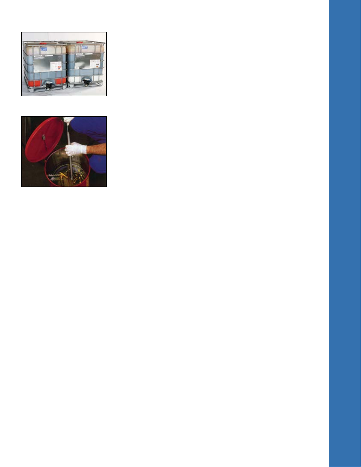
Arrange Totes and Drums - Totes and drums should be arranged with the “ISO” side on the
left and the “CAT” side on the right. (photo 10b) The lower cylinders of the pump are labeled as
to which hose goes to which side. When moving the pump, be sure to keep tote/drum hoses on
their proper side. It is a good idea to place roofing felt in the pumping area, especially under
the tire being filled, for easier clean-up. (photo 10c)
2. Assemble Tools and Supplies - Make certain all necessary tools (valve core remover, extra
valves, screws, hammer, screwdriver, pliers, bags, etc.) are on hand. If possible, stage the tires
to be filled in the vicinity of the pump.
10a
10b
10c

11
III. PREPARATIONS
3. Prepare Totes
a) Remove shipping cap. Remove foil if it is present.
b) Liberally grease the threads on the tote connector and screw
it onto the tote’s ball valve and hand tighten. (photo 11a)
DO NOT TIGHTEN WITH A WRENCH.
c) Remove dust cap from kamlock on suction/supply hose.
d) Apply grease to the tote connector and connect the kamlock
to the tote connector. Lock kamlock in place by pulling back on
the handles.
e) Connect the supply/suction hose to the king combo on the
intake side of the pump and tighten hose clamp.
f) Repeat for both “ISO” and “CAT” sides.
4. Install Desiccant Cartridge - It is essential that a desiccant
is used on the “ISO” side tote as the material is moisture
sensitive. The “CAT” side tote will need to be vented.
To install the Desiccant Cartridge:
a) Remove white 2” inch center bung on the “ISO” side tote.
b) Apply grease liberally to the threads on the desiccant holder. This will make removal easier.
c)
Pierce both ends of the desiccant container using a screwdriver
or other punch tool. Two or
three holes on each end is sufficient.
d) Loosen top hose clamp on desiccant sleeve and insert desiccant container with inspection
window facing forward and the arrow pointing down.
e) Tighten hose clamp. (photo 11b)
Note: It is essential to change the cartridge when desiccant in the inspection window turns
from blue to pink, as moisture will contaminate the material.
5. Connect Hoses - Connect 1 1/2 ” clear supply hoses from the pump to the tote connectors
or drum valve assemblies. Make certain that the “ISO” side hose is connected to the “ISO”
side tote/drum and that the “CAT” side hose to the “CAT” side tote/drum. Fully open ball valves
when pumping. Ball valves should be closed when not in use. On drums, be sure to open 3/4“
air vents.
6.
Air Supply - Connect air line to the pump. Adjust air regulator to 80 psi (550kPa). Note:
Adjusting the regulator to higher pressures provides only a modest increase in pump speed.
Higher pressures increase the risk of premature air motor failure. The easiest way to increase
the speed on the pump is to fill the tires through the largest valve stem possible. A tire with a
large bore air-water valve can be filled up to 4 times faster than a tire with a standard valve.
11a
11b

12
IV. TIRE FLATPROOFING PROCESS
Flatproofed tires are pressurized not with air, but with
flatproofing material. It is important that before processing,
you know the operating pressure of the tire. Refer to the
manufacturers’ data for the tire you’re filling or the current
Yearbook by the Tire and Rim Association, Inc. (photo 12a),
ETRTO Standards Manual or the JATMA Yearbook to determine
proper pressurization for each tire. Tires must be correctly
pressurized for optimum performance in ride, footprint and
durability. In no case should a tire be pressurized above the
maximum pressure indicated on the tire sidewall.
In addition to the pressure, you should know the estimated
pounds of flatproofing material necessary to fill the tire. Accella
Tire Fill Systems has a Flatproofing Weight Chart in addition to a
Computerized Flatproofing Estimator on www.accellatirefill.com
to help you approximate weights and costs for flatproofing tires.
(photo 12b)
Note: These provide only an estimate of the amount of
pounds required to fill each tire. Use the following procedures
when flatproofing tubeless tires (for tires with tubes, see the
Miscellaneous Section).
Start-Up Procedures
1. Remove manifold head, mixer, and fluid gun from the solvent
container and wipe off with a rag to remove excess alcohol.
Visually check to ensure all the items are free of any residue. If
any solvent is accidentally pumped into a tire it will contaminate
the material and could result in a failure. Note: only cleaned
parts should be stored in the parts container on the pump.
2. Some customers prefer to affix the high pressure flexible
“blue” whip hose, part number EQ1850H, (photo 12c) to the
mixing tube rather than the high pressure swivel. Either
configuration can be used and is based on customer preference
and/or convenience. Note: rather than show both methods in
the Manual, the photos presented here will focus on the high
pressure swivel and its attachments.
3. Apply a coat of grease to all quick connects and use Teflon®
tape at all connections (ie. at both ends of the mixer tube and/or
whip hose).
4. Insert all three mixing elements into the mixing tube. Do
not use broken elements. Note: as elements are fragile, it is
important to always keep extra available (photo 12d).
Teflon® is a registered trademark of Dupont.
12a
12b
12c
12d

13
IV. TIRE FLATPROOFING PROCESS
5. Attach manifold head to the base using the quick connects.
Be sure to attach the correct side up (it will read “ISO” and
“CAT”). On the opposite side, the manifold head will read, “this
side down”.
6. Connect mixing tube to the manifold head. Attach pressure
gauge. Attach fluid gun to mixing tube or whip hose. Complete
assembly by attaching to manifold handle. Tighten both ends.
See our TyrFil Flushless Pump Parts Catalog, for proper
assembly of manifold.
7. Adjust air supply to the pump to 80 psi. Make sure the
manifold hand valve is in the off position when turning pump on.
8. Slowly open the hand valve and run 2 cycles on the meter
into a waste container to rid the system of any residual solvent.
A cycle is one complete up and down stroke. When pumping
material, make certain manifold and dispensing valves are fully
open. Partially opening the valves can cause improper ratio of
“ISO” and “CAT” side material.
9. Make sure the 1000 psi cylinder pressure gauges are within
50 psi of each other, (photo 13a) when pump is operating.
10. Prepare a quality control sample sometime during the filling
process. It is important to prepare a sample with each batch
of tires flatproofed as a means of checking for a proper cure.
Pump a sample [approximately 1/2 - 1 cycle (6-12 oz/.15-.3 kg)
into a self-locking plastic bag].
Note: Write the date and lot number on the bag and lay it on
the flatproofed tire during the curing process. After the cure is
completed, the sample should be retained for future reference
should any problems arise while the flatproofed tire is in service.
11. Reset stroke counter or electronic flow counter to zero.
(photo 13b) Note: electronic flow counter indicates pounds
unless programmed to read in kilograms.
13a
13b

14
IV. TIRE FLATPROOFING PROCESS
Processing
Important: Never leave a pump operating unattended.
1. Position tire vertically in the tire cage with the valve stem
between the 4 o’clock and 8 o’clock position, with 6 o’clock
being ideal. (photo 14a)
2. Select the proper core holder and filling adapter for the valve
stem. To avoid leaks, make sure all gaskets are in place and
threaded connections are assembled with Teflon® tape.
Remember, tires with longer or angled valve stems will take
longer to fill because of the increased back pressure. Whenever
possible, use the largest valve stem available. (photo 14b)
3. Remove the valve core from the tire that has been inflated
for prestretching. It is important to keep the bead seated. Do
not let air bleed excessively. See page 15 for Bead Reseating
instructions.
4. Insert the valve core into the core holder and immediately
connect the filling adapter to the tire valve stem. Attach the filling
adapter to the fluid gun.
5. Fully open the valve on the manifold and begin filling the tire.
(photo 14c)
6. Check the internal tire pressure frequently by closing the hand
valve on the manifold and opening the pressure gauge valve.
7. Continue pumping until the tire has enough pressure to keep
the bead seated or tube inflated. To check the level of material in
the tire, tap the casing lightly with a hammer (unfilled portion will
sound louder).
8. Close the manifold hand valve. Insert a hypodermic needle
into a tread groove at the 12 o’clock position just deep enough
to vent trapped air. Stop inserting further when you start to hear
air escape from the tire. For steel belted tires and thick casings
(greater than 12 ply) you will need to drill a 1/8 inch hole through
the tire to assist needle insertion. (photo 14d)
9. Use of Accella Tire Fill Systems’ specially designed
SmartNeedle™ Inserter will make this much easier, safer, and
will avoid damaging the needle or your hand. (photo 14e)
14a
14b
14c
14d
14e

15
IV. TIRE FLATPROOFING PROCESS
10. After insertion of the needle the pressure will drop. It is
necessary to maintain at least 20 psi (30%) until all the air is
completely vented and the tire is full of flatproofing material. It is
necessary to maintain at least 30% of the operating pressure to
ensure that the tire beads remain seated.
11. Turn the manifold valve back on and continue pumping.
Check the tire pressure often during the venting stage. To keep
the pressure from dropping too quickly, place a finger or thumb
over the needle to stop the air from escaping (photo 15a). Note:
while it is essential to “vent” or remove all of the air from the
tire, keeping some air pressure during the flatproofing process
assures the tire will keep its bead seat and remain on the wheel.
If the air is released too quickly, the bead could collapse. If this
happens, the flatproofing process must be stopped and the
bead reseated before continuing. Bead Reseating Instructions
as stated earlier, if air is released too quickly from a tire being
flatproofed, the bead can collapse. Should this occur, the
bead can be reseated using the Flushless Manifold while still
attached to the tire’s valve system.
1. To reseat the bead, turn off the manifold hand valve and
remove the SmartGauge™ from the manifold.
2. Temporarily remove the needle from the tire and plug the
hole with a nail. Insert the nail only deep enough to seal the
hole, because you will be removing the nail after the bead has
seated.
3. Attach the air hose to the male quick connect on the
Flushless Manifold.
4. Open the 1/4” ball valve on the SmartGauge™ stem
located on the manifold to inflate the tire. After the bead has
seated, add enough pressure to the tire to prevent another
collapse.
5. Remove the air hose from the quick connect and replace
the SmartGauge™. Turn on the manifold hand valve and
continue filling the tire.
6. Finish by removing the nail and reinserting the needle to
vent the tire.
12. Continue pumping until material flows from the hypodermic
needle (photo 15b) and then turn off the hand valve. Remove
the needle slowly from the tire and plug the hole with a roofing
nail or a sheet metal screw (photo 15c). Note: needles are
reusable if properly cleaned with solvent.
15a
15b
15c

16
IV. TIRE FLATPROOFING PROCESS
13. Check tire pressure. Turn on the hand valve and pressurize
the tire to its recommended psi. Remember, all tires, especially
small tires, will pressurize fast. Always pressurize to the
manufacturers’ specifications (photo 16a). Caution! There is
a fundamental difference between pressurizing a tire with air
and pressurizing a tire with flatproofing materials. Gasses are
compressible while liquids are uncompressible. Pressurizing a
tire with air is a gradual process with pressure building slowly
from the initial introduction of air. With Accella Tire Fill Systems
flatproofing materials, the tire is vented during the filling process
so there is very little pressure build-up until the tire is totally
filled. Then the pressure builds rapidly, with the pumping of a
very small additional amount of material stretching the carcass.
14. Depress the plunger on the fluid gun and reinstall the
valve core by turning clockwise making certain the valve core
is securely seated. Pull back on the plunger and check the
pressure gauge. If the tire has been sealed, the pressure gauge
will read zero. Then disconnect the fluid gun and place over
waste container.
15. Lay filled tire on its side and place on a pallet. Handle tires
with tubes carefully, as some tubes split easily. Do not cure tires
in an upright position. Upright curing can create an air pocket on
top and a flat spot on the bottom.
16. Lay the sample on the filled tire for use in checking the
progress of the cure. Use a tire marker to identify stroke or
weight count and psi on the tire (photo 16b). Document in the
flatproofing log. This log is used to record processing data and
customer warranty information (photo 16c).
Note: It is very important to keep accurate records as this ensures adequate warranty
documentation in the unlikely event that the need arises. In the Flatproofing Log, you should
include: date of processing, customer name, pumper’s name, type of tire, product used, lot
#, final tire pressure and pounds of material. All entries should be in ink and a copy should
be made of each entry sheet. Flatproofing log sheets are available through Accella Tire Fill
Systems for your convenience.
17. Put rim stickers on the wheel.
Note: Warmth speeds the cure.
Tires flatproofed with materials
at 72° F (22° C) and placed in a
warm room [minimum 72° F (22°
C)] will cure 70% in 24 hours and
100% in 72 hours. Tires can go
into service 24 - 48 hours after
processing.
16a
16b
16c

17
IV. TIRE FLATPROOFING PROCESS
Tire Pressurization
Overpressurization
Do not overpressurize tires. In addition to the potential danger
of bursting the tire, overpressurization will cause “crowning”
(extreme tread wear at the center of the tire) and possible
splitting of the carcass upon impacting curbs, potholes, etc.
Once the material has cured, there is no way to correct this
problem. If a tire becomes overpressurized during the filling
process, close the manifold valve and open drain valve. Pressure
inside the tire will force the flatproofing material out through
the drain valve. Close the drain valve and check pressure again
(photo 17a ).
Underpressurization
Do not underpressurize the tire. This can cause excessive flexing
of the casing and material, which may lead to overheating and
eventual tire failure. Unlike a tire filled with air, virtually a complete
loss of pressure can result from the leakage of only a very small
amount of material from the tire after it is filled. If leakage is
observed, the tire may need to be repressurized and resealed.
Repressurization
Voids or air pockets are created when uncured material escapes
from a newly flatproofed tire. Once the flatproofing material
has cured, a tire with voids can be repressurized by injecting
additional material through the sidewall. Contact the Accella Tire
Fill Systems Technical Department prior to sidewall injection.
Clean-Up Procedures
Proper shutdown and cleaning of the pump and equipment is
vital. When you have finished processing tires, the equipment
must immediately be cleaned of all reactive materials. If left in
the machine, they will cure, become insoluble, and clog the
equipment.
1. Open the hand valve over a waste container until the pistons are in the down position (photo
17b). This allows the piston rods to be submerged in the throat seal lubricant. Then close the
manifold hand valve.
2. Turn off the air supply to the air motor by closing the ball valve at the regulator.
3. Open the manifold valve to release the pressure inside the cylinders and hoses. Close the
manifold valve when the pressure on the cylinders is zero (photo 17c).
17a
17b
17c

18
IV. TIRE FLATPROOFING PROCESS
4. Ball valves should be closed when not in use (photo 18a).
5. Close the pressure gauge ball valve and remove the tire
pressure gauge. Rest the manifold on the ground or breakdown
table for easier disassembly and clean-up.
6. Remove the whip hose and/or mixing tube from the manifold
head (photo 18b). Allow excess of product to drain over the
waste container. Store whip hose in solvent.
7. Separate the manifold head from the hand valve (photo 18c),
and wash manifold head in the solvent. Open ball valve on the
manifold and rinse the gauge port with solvent. Store manifold
head in the solvent when clean.
8. Eject the mixing elements from the mixing tube and wash the
elements in the solvent. Store mixing elements in a safe place
to avoid breakage. Clean mixing tube with a steel brush (photo
18d) and place mixing tube in solvent container.
9. Wipe off any excess material from the manifold handle with a
clean rag and place on hanger.
10. Thoroughly clean and store tools in their proper place.
11. Clean all mixed material off floor and machine.
18a
18b
18c
18d

19
V. PUMP MAINTENANCE
Proper maintenance is critical to long equipment life, reliability
and efficiency. This section covers the maintenance to our
TyrFil Flushless Pump. Flatproofing does not have to be a dirty
business as long as the pump is kept clean and in good working
order.
Fluid Gun and Manifold - Clean after each use with 99%
isopropyl alcohol.
High Pressure Hoses - Replace “ISO” side hose once a year
under normal operating conditions. Normal refers to the
equipment being used at least once per week. For long term
storage, the high pressure hoses should be removed and the
lower cylinders sealed with airtight plugs.
Pressure Gauge - Replace if cross contamination occurs.
Lower Cylinders - Seals should be replaced if line pressures
fall below the normal operating range or excessive cup seal
leakage occurs.
Suction Side Hoses - Replace “ISO” side hose once a year. Replace “CAT” side hose when
damaged. If cross contamination occurs, all hoses must be replaced. For long term storage,
remove suction hoses and the lower cylinders sealed with air tight plugs.
Wet Seal Cups - During initial setup, the wet seal cups should be filled 1/4 full with throat
seal liquid (TSL) oil. This oil provides critical lubrication to the piston rods and also serves as
a moisture barrier for the Teflon® packings. TSL oil is consumed during normal operation and
therefore it should be checked on a weekly basis even when the pump has not been used. Do
not run cup seals dry as seal damage will result (photo 19a).
The nut packing (oil cups) require periodic adjustment. Use the spanner wrench supplied with
the pump to tighten if they are loose. Packings should be hand tightened only. Keep just tight
enough to prevent leakage, no tighter.
Note: Over tightening will damage the Teflon® seals. These should be checked on a daily
basis (photo 19b).
With normal use the TSL oil will change color as flatproofing material slowly penetrates the
seals. “ISO” side material will begin to harden once it has accumulated in the cup. When
“ISO” side material begins to solidify in the cup, scoop out the jelled material. Once the cup
has been cleaned, refill with clean TSL oil and double check the seal to see if it is tight.
Replacement parts are available through Accella Tire Fill Systems. See our TyrFil Flushless
Pump Parts Catalog.
19a
19b

20
VI. MISCELLANEOUS
Tires with Tubes
Step 1. Position the tire in the normal filling position (photo 20a).
Step 2.
Remove the valve core from the stem and attach the tube
deflator to the valve stem.
Step 3. Apply a vacuum to the tube. When the tube is deflated,
drill the venting hole at the 12 o’clock position in the tread groove.
It is important to note that for very thick tires, you must use a
drill bit long enough to drill through the tire. It is recommended
that the Flatproofing Technician practice with an unmounted tube
before performing this procedure in the tire. The vacuum device
will make a distinct sound when all of the air has been removed
from the tube. It is important that you can identify this sound. If
not, you will not know when the tire can be safely drilled.
Step 4. The tube must be expanded before processing. To do
this, momentarily replace the valve core and inflate the tire with
air to half of the recommended pressure. This step will ensure
that the tube will inflate properly.
Step 5. Remove the valve core and fill the tire as you normally
would.
Step 6. When 30%-50% of the final desired pressure has been
reached, insert the needle in the vent hole and puncture the tube.
Step 7. Continue filling the tire. Maintain 30%-50% of the final
desired pressure in the tube at all times. Regulate by covering
and uncovering the needle with your finger. This pressure will
keep the tube seated in the tire (photo 20b).
Step 8. The tire is filled when material flows from the needle
(photo 20c).
Step 9. Remove the needle and insert a nail into the vent hole
to seal the tire. Remember, the nail must also be long enough to
penetrate the tire and tube (photo 20d).
Step 10. Pressurize the tire. Lay it flat to cure.
Caution: Failure to keep pressure in the tube during the venting process could cause the tube
to sag allowing the needle to puncture another hole or rupture the tube.
Tires with Tubes (under 12 ply)
Tires in this category can be flatproofed in the same manner as filling a tube-type tire with one
exception, never allow the pressure to drop to less than 40% of the final pressure.
20d
20c
20b
20a
Table of contents
Popular Water Pump manuals by other brands

Pentair
Pentair AURORA 411 Installation maintenance repair manual

Graco
Graco Series B Instructions-parts list

DAYLIFF
DAYLIFF DP SOLAR Installation & operating manual

Pentair Hydromatic
Pentair Hydromatic SPD50H owner's manual

Sulzer
Sulzer AS 0530 Installation and operating instructions

Daikin
Daikin Rotex RPS4 Operating and installation instructions

Sulzer
Sulzer SES User and maintenance manual

Hydor
Hydor AQAMAI KP Series user guide

Grundfos
Grundfos MSS Series Installation and operating instructions

GORMAN-RUPP PUMPS
GORMAN-RUPP PUMPS 80 Series Installation, operation, and maintenance manual with parts list

Ozito
Ozito SBP-0121 instruction manual

Grundfos
Grundfos APG Series Installation and operating instructions