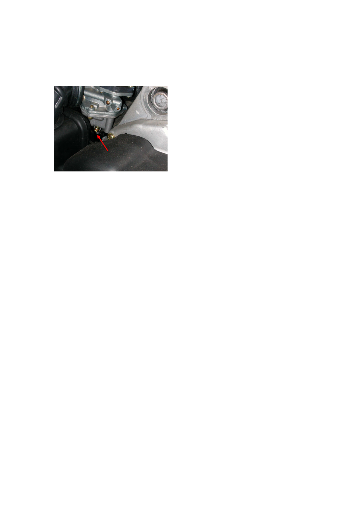
CARBURETOR FLOAT BOWL DRAIN
Periodically, the float bowl should be drained to remove condensation.
To drain the float bowl, use the following procedure.
1. Attach a hose to the float bowl
drain and direct it into a container.
2. Loosen the drain screw and allow
the gasoline and condensation to
flow out.
3. Tighten the drain screw securely
and remove the hose.
SEAT LOCK
1. To remove the seat, pull the seat lock knob out (located at the).Raise
the rear end of the seat and slide it rearward.
3. To lock the seat into position, slide the front of the seat into the seat
retainers and push down firmly on back of seat. The seat should
automatically lock into position.
Warning: Make sure the seat is secure before mounting the ATV.
Severe personal injury may result if the seat is not properly secured.
SAFETY FLAG/BRACKET
A bracket is provided for mounting a flag at the rear at the rear of the ATV.
The flag should be displayed to make the ATV more visible.
TRANSPORTINGATV
When transporting the ATV, we recommends that the ATV be in its
normal operating position (on all four wheels) and the following
procedure be used.
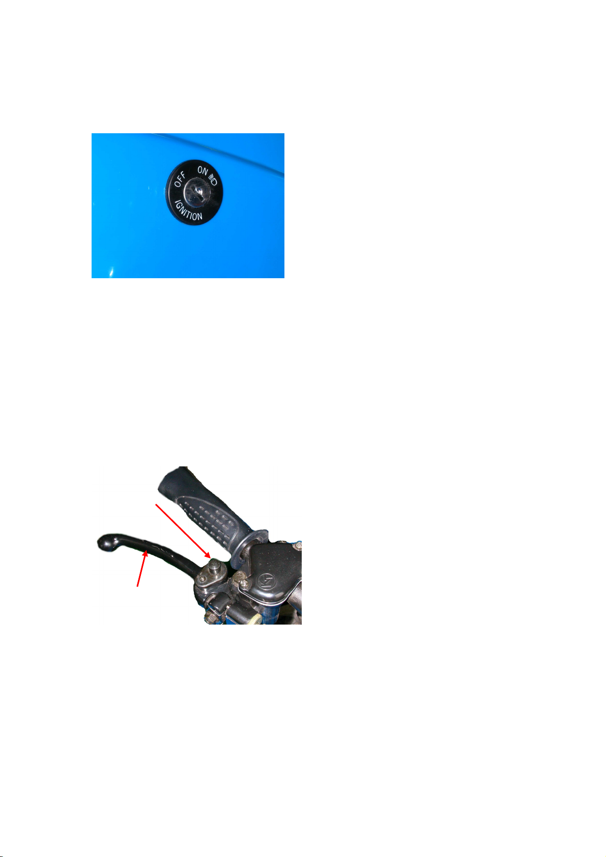
1. Engage the brake lever locks.
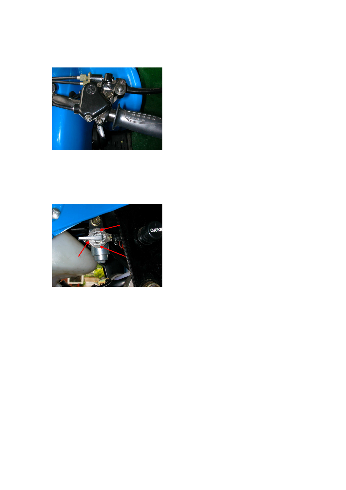
2. Turn the fuel valve OFF.
3. Secure the ATV with load rated hold-down straps.
NOTE: Suitable hold-down straps are suggested. Ordinary rope is not
recommended because it can stretch under load.
Caution: If using additional hold down straps in any other areas, care
must be taken not to damage the ATV.
Caution: When transporting theATV, make sure the brake lever lock is
engaged and the ATV is properly secured.
DRAIN