Accu Cutter 2001EVO User manual

Accu Cutter Company
160 Stover Drive, P O Box 1170, Carlisle, Pennsylvania 17013 800-345-0062 (Fax) 717-241-2350
“We’ve stayed in business by cutting corners!” 1
Operator’s Manual
Model 2001EVO 12” Bench Shear
(November 2008)
Unpacking the 2001EVO Shear
Care should be exercised unpacking the shear. To facilitate proper packing, the shear was
partially disassembled. In order to reassemble the shear for safe operation, it is essential that you
locate all of the parts for the shear before any packing materials are discarded. The following is a list
of the parts or assemblies included with your shear:
1. Main body of Shear.
2. Shear handle with foam grip.
3. Left safety shield.
4. Drop-off Gauge and rod.
5. Two bolts and lock nuts for Shear handle.
6. Ball hex wrench (5/32”).
7. Standard ball hex wrenches, 5/32” & 3/16”
If any parts are missing, please call Accu Cutter before attempting to reassemble the shear.
* * * * *
Work Surface
Make sure the work surface is clean and free from debris. The shear should sit flat and level.
There should be sufficient room on all sides of the shear so nothing will interfere with its safe opera-
tion.
* * * * *
Assembling the 2001EVO Shear
1. Install the Handle. If the safety shield has been removed, it is easier to install the handle
before the safety shield is installed. However, the shear should not be used before the safety
shield is installed. To install the handle, locate the two 3/8” x 1 1/2” bolts and lock nuts. Slide the
flat end of the handle between the two aluminum triangles, line up the holes, and insert the bolts.
(No. 6, Figure 3, Page 4) A large Phillips screwdriver and 9/16” wrench are required.

Accu Cutter Company
160 Stover Drive, P O Box 1170, Carlisle, Pennsylvania 17013 800-345-0062 (Fax) 717-241-2350
2“If it doesn’t say Accu Cutter, it isn’t!”
2. If removed, install the Safety Shield. The safety shield attaches to the left side of the
bottom blade carrier. (Figure 1.) The safety shield is attached with two pan head screws, one at each
end of the shear. Hold the safety shield with the notched end down and toward the ruler. You will
see the two pan head screws in the bottom blade carrier. Remove and use these screws to install the
safety shield. To facilitate installing the safety shield, turn the body of the shear so the side with the
blades is farthest away from you and tilt the body of the shear away from you.
Figure 1.
Now that the 2001EVO Shear has been assembled,
you must verify the setup before using the shear.
Proper Setup of the 2001EVO Shear.
Prior to shipping, the shear was examined and tested. It was in good working order. How-
ever, shipping can sometimes be eventful, so it is necessary to perform some tests on the shear before
you place it in regular service.
1. The Blades. The blades should be examined for nicks or other damage that may have oc-
curred during shipping. If there is any damage, call Accu Cutter immediately. If the blades appear
okay, you should next check the shear action.
2. Testing the Shear Action. Slowly lift the handle until the blades are open fully. There
should be some resistance or stiffness in the action of the shear, and the shear handle should remain

Accu Cutter Company
160 Stover Drive, P O Box 1170, Carlisle, Pennsylvania 17013 800-345-0062 (Fax) 717-241-2350
“We’ve stayed in business by cutting corners!” 3
in the upright position when you release it. Now slowly begin to lower the handle closing the blades.
You should be able to do so without incident. However, if you hear a grinding noise or feel unusual or
excessive resistance or stiffness, stop immediately. Moving the handle farther could cause serious
damage to the blades. Examine the shear for obstructions. If none are found, lift the handle to open
the blades, follow the instructions for "Adjusting The Shear Action" in this Manual.
3. The Top Guide (Ruler). The top guide must be square to the blades for proper cutting.
With the upper blade in the closed position, use a drafting square to check the angle between the top
guide and upper blade. If it is not a right angle, used a 3/16” hex wrench to loosen the screws in the
top guide to adjust it. When tightening the screws, pull the ruler towards you.
* * * * *
Installing The Drop Off Gauge
The Drop Off Gauge is used to make repetitive cuts. By providing a stop for the material,
several cuts of the same length may be made without measuring each cut before it is made. There
are three positions (tapped holes) for the drop off gauge located on the right side of the bottom blade
carrier. They correspond to the three possible positions for the top guide.
To use the Drop Off Gauge (pictured above) screw the rod into a hole that corresponds to the
location of the top guide. Place a piece of material on the shear table in position to cut a piece the de-
sired length from the right side of the material. Slide the Drop Off Gauge until it is touching the end
of the material and tighten the knob. Make a test cut. It the piece is not the correct length, loosen the
knob and adjust as needed.
NOTE: Most drop off gauges are tightened with a bolt the puts pressure on the rod and also
makes a mark in the rod in the process. After repeated use the marks can interfere with the accurate
adjust of the drop off gauge. Accu Cutter’s Drop Off Gauge is secured by pinching the rod. As a re-
sult, there are no marks on the rod to interfere with the adjustment of the Drop Off Gauge.
* * * * *

Accu Cutter Company
160 Stover Drive, P O Box 1170, Carlisle, Pennsylvania 17013 800-345-0062 (Fax) 717-241-2350
4“If it doesn’t say Accu Cutter, it isn’t!”
Adjusting the Shear Action
The shear action is tested and properly adjusted and lubricated prior to shipping the shear.
The action may appear to be stiff, but it is set that way for two reasons. First, if the action is too
loose, the blades can move in and out of adjustment depending on the way you move the handle. This
will result in poor and irregular cutting and dramatically shorten the useful life of the blades. One
symptom of a loose shear is that the metal bends instead of cutting. Second, because of possible in-
jury, you should never remove your hand from the handle of the shear while the blades are open any
amount. However, if you do so inadvertently, the stiff action of a properly adjusted shear will cause
the blades to stay in that position so they will not close accidentally.
Under normal conditions, the shear should not require adjustment by you. However, if you
are having a problem, follow the procedures in this Manual carefully while referring to Figures 3 and
4. If doing so does not resolve your problem, call Accu Cutter for assistance.
Figure 3.
To correctly adjust the shear action, carefully follow all of the steps below.
1. Examine the shear to determine if any parts, including the blades, are damaged,
broken, or missing. If any are, call Accu Cutter for assistance. If none are, con-
tinue with this section.
2. Lift the handle until it is open fully. If the shear is too loose and the handle will
not stay in the open position, temporarily tighten bolt Number 3, Figure 3 above.
3. Move the bottom blade away from the top blade. There are three setscrews visible
in the slots in the shear table. Using the ball hex provided with the shear, loosen
the three setscrews so they are no longer touching the bottom blade. Next loosen
the four button head bolts holding the bottom blade. A standard 5/32” hex head
wrench is required. Once the bottom blade is loose, move it away from the top
blade creating a gap, and secure it by lightly tightening one of the button head
screws.

Accu Cutter Company
160 Stover Drive, P O Box 1170, Carlisle, Pennsylvania 17013 800-345-0062 (Fax) 717-241-2350
“We’ve stayed in business by cutting corners!” 5
4. Carefully loosen bolt Number 3 in Figure 3 above. You should now be able to
move the handle up and down without the top and bottom blades touching each
other.
5. Check all moving parts for proper lubrication and lubricate as needed. White li-
thium grease is preferred, but heavy machine oil may also be used. Silicon sprays
evaporate rapidly and are not recommended.
6. Adjust the bolts in the following sequence:
a. The bolts through the handle should be tight. (Number 6, Figure 3)
b. The other bolts through the triangles (Numbers 4 and 5, Figure 3) should
be loose enough that you can turn them with your fingers when moving
the handle from side to side.
c. Bolts Numbers 1 and 2, Figure 3, should be tight but not dead tight. You
should still be able to move the handle up and down.
d. Bolt Number 3, Figure 3, is the last one tightened. It is a feel adjustment.
It should be tight enough to keep the handle in the upright position, but
not so tight that you can’t operate the shear.
7. Adjust the blades following the instructions in the section below, Removing, In-
stalling and Adjusting the Blades.
* * * * *
Removing, Installing, and Adjusting the Blades
The drawing to the right is a cross sec-
tion of a portion of the Shear. It shows the
general relationship of the work table, top and
bottom blades, and the set screws used to ad-
just the bottom blade. Refer to it as you read
the instructions below. It will help you visual-
ize the instructions.
ALWAYS WEAR GLOVES when
working with blades. They should always
be considered very sharp even if they
have been used. Shear blades can and
will cut you and can cause serious harm
to you or someone working with you.
Removing the Blades
1. Remove the top guide from the worktable. (Optional)

Accu Cutter Company
160 Stover Drive, P O Box 1170, Carlisle, Pennsylvania 17013 800-345-0062 (Fax) 717-241-2350
6“We’ve stayed in business by cutting corners!”
2. Remove the safety shield.
3. Using the ball hex provided with the shear, loosen the setscrews so they are no
longer touching the bottom blade.
4. Loosen the four button head bolts holding the bottom blade. A standard 5/32” hex
head wrench is required.
5. Move the bottom blade away from the top blades so there is a small gap.
6. Loosen the four bolts holding the top blade. After all are loosened, remove the
bolts one at a time using care so the blade doesn’t drop as the bolts are removed.
A leather glove is recommended for holding the blade while removing it. The top
blade may be in either the open or closed position depending on your preference.
A 7/16” wrench is required.
7. After the top blade has been removed, remove the four button head bolts holding
the bottom blade and remove it from the shear.
Installing the Blades
1. Remove the top guide or ruler. (Optional)
2. Carefully insert the bottom blade in its carrier. If the top of the bottom blade is
not level with the blade carrier and worktable, place shims under the entire blade
to raise it until it is level. Align the holes and insert but do not tighten the button
head bolts. Note the orientation of the beveled edge of the blade in Figure 4
above. A leather glove is recommended for holding the blade while installing it.
3. With the shear handle in the open position, align the holes in the top blade with
the holes in the carrier for the top blade. Note the orientation of the beveled edge
of the blade in Figure 4 above. A leather glove is recommended for holding the
top blade while installing it.
4. Insert the hex head bolts and lock washers. Do not tighten any of the bolts until
they have all been inserted. Once they have all been inserted, tightened the two
end bolts and then the two middle bolts. Be careful to not over tighten any of the
bolts.
5. After installing the top blade, lower the operating handle so the top blade is in
the closed position.
6. Slide the edge of the bottom blade against the top blade and lightly tighten the
four button head bolts. When lightly tightening the button head bolts, remember
you want the bottom blade to move or slide on the blade carrier surface while you
are adjusting it, but you do not want the blade so loose that it will rock or one
edge lift off of the carrier surface.
7. Read the section below on Adjusting Blades beginning with Step 6.

Accu Cutter Company
160 Stover Drive, P O Box 1170, Carlisle, Pennsylvania 17013 800-345-0062 (Fax) 717-241-2350
“We’ve stayed in business by cutting corners!” 7
Adjusting the Blades
The following instructions are for adjusting the blades of the shear to a “zero” gap or clear-
ance. This is the preferred setting for lighter materials like .020” brass, .025” aluminum, and .060”
flexible plastic. If your application is for heavier materials within the design limits of the shear, you
may prefer a clearance set with feeler gauges. The general procedure for adjusting the blades is the
same except you would use feeler gauges in Step 7 to determine the proper location and gap for the
bottom blade and a sample of your material to test the cut of the shear.
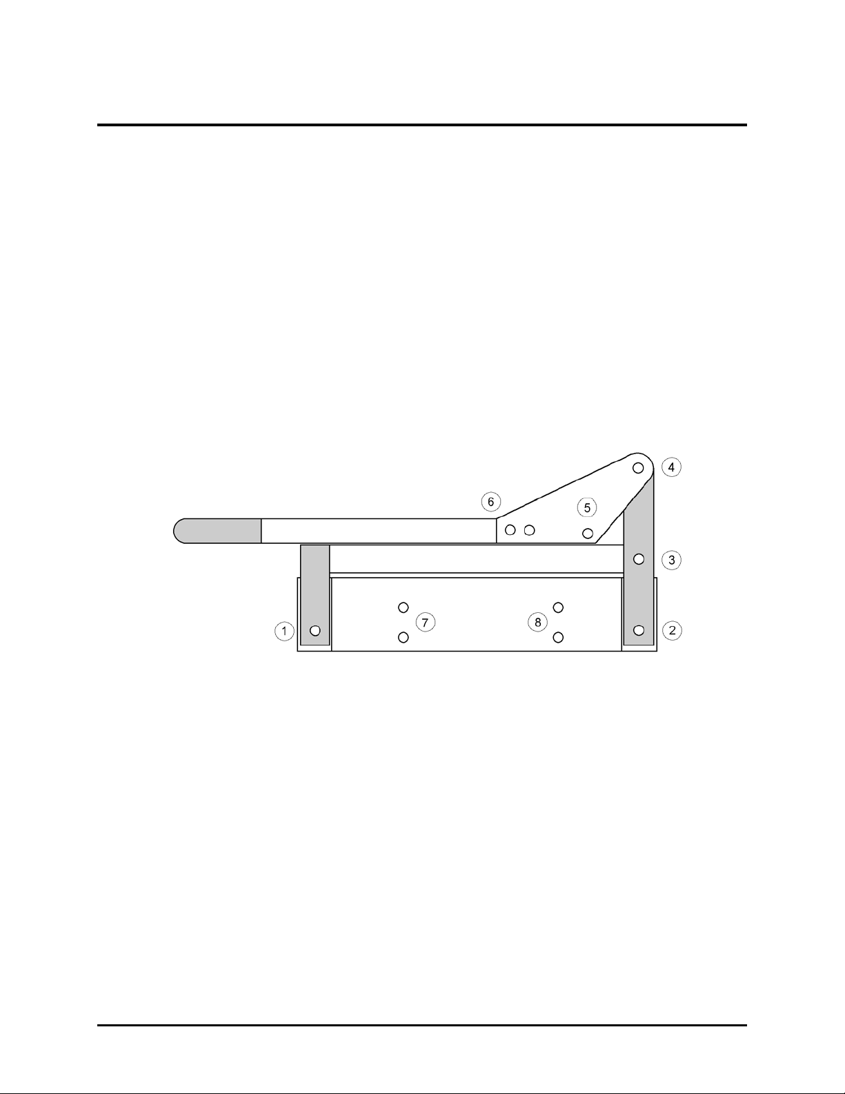
1. Lower the operating handle so the top blade is in the closed position.
2. Remove the safety shield.
3. Using the ball hex provided with the shear, loosen the setscrews so they are no
longer touching the bottom blade.
4. Loosen the four button head bolts holding the bottom blade. A standard 5/32” hex
head wrench is required. If the top of the bottom blade is level with the blade car-
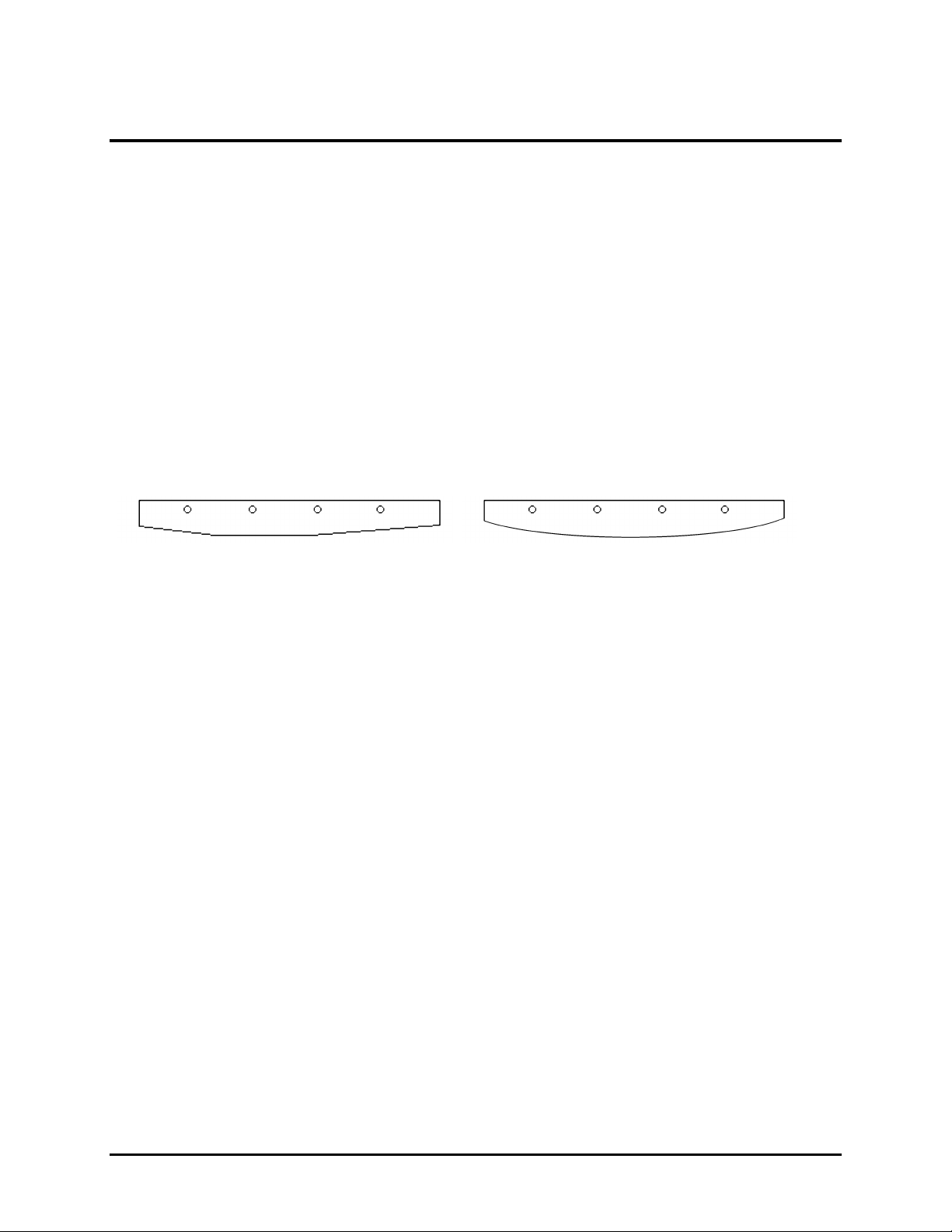
rier and worktable, go to Step 5. If it is not, remove the button head bolts and
place shims under the entire blade to raise it until it is level. Align the holes and
insert but do not tighten the button head bolts. Note the orientation of the be-
veled edge of the blade in Figure 4 above. A leather glove is recommended for
holding the blade while installing it.
5. Using your fingers, push the bottom blade against the top blade and lightly tigh-
ten the four button head bolts.
6. Make a test cut with a piece of paper. CAUTION: When you are making your
test cut, if you hear an unusual or grinding noise or you feel unusual or excessive
resistance or stiffness, stop immediately. Moving the handle further could cause
serious damage to the blades. Before moving the handle further, back off or loo-
sen the bottom blade and start the adjusting process over.
a) If the shear cuts the paper completely, tighten the four button head bolts,
and tighten the setscrews against the bottom blade.
b) If the shear does not cut the paper completely, try loosing the button head
bolts in the problem area and retighten while applying additional pres-
sure. If this is unsuccessful, use the setscrews as need to apply the pres-
sure needed. Do not over tighten the setscrews. Once the shear cuts the
paper completely, tighten the four button head bolts, and tighten the set-
screws against the bottom blade.
7. If the top guide was removed or loosened, reinstall or tighten it. See the instruc-
tions for squaring the top guide.
8. Replace the safety shield.
* * * * *

Accu Cutter Company
160 Stover Drive, P O Box 1170, Carlisle, Pennsylvania 17013 800-345-0062 (Fax) 717-241-2350
8“We’ve stayed in business by cutting corners!”
Shear Blades
Curved Power Blades - For years the blades of a scissors type shear like the 2001 were
straight. While they provided an acceptable cut, the amount of effort needed to cut material in-
creased dramatically near the top of the shear or end of the cut. The original Power Blade (Figure 1.)
was developed by Accu Cutter to reduce the amount of effort needed to cut material. Adding steps to
the blade accomplished this. Now, replacing the steps with a graceful curve has further refined the
Power Blade. (Figure 2.) The resulting Curved Power Blade is easier to use, smoother, and has a
superior cut.
The Curved Power Blades were developed by Accu Cutter and are currently available for
cutting metal or plastic. They are standard on the 2001 Shears and are available as replacement
blades for all 2001 Shears. The bottom blade remains unchanged.
Figure 1. Figure 2.
Combination Blades -The upper blade of a shear is traditionally designed to cut either
plastic or metal, but not both. The dedicated blades are still the best choice if you are going to cut
only metal or only plastic. However, with the combination blade developed by Accu Cutter for the
2001 & Mark V 12” Shears, you can cut both metal and plastic with the same blade and still get good
results. The results will not be as good as a dedicated blade.
Replacement Blades & Sharpening Services –The cut of any shear, no matter how good,
cannot be any better than the quality and sharpness of the blades. Accu Cutter supplies quality,
hardened, tool steel blades with all of its shears and maintains an inventory of the same blades for
replacements. A sharpening service is also available for all shear blades. Whether you are replacing
blades or having them sharpened, it is recommend that you replace/sharpen the top and bottom
blades at the same time. If you don’t, you run the risk of changing the wrong blade and damaging
the good blade. Proper adjustment is also important. The first cut can cause more wear or damage
than the next thousand! If you are having a problem, call us Accu Cutter.
2001 Shear (12”)
BLM
Upper, Metal Cutting
$75.30
BLC
Upper, Combination
$75.30
BLP
Upper, Plastic Cutting
$75.30
BLL
Lower
$75.30
BLS
Sharpening, All Types
$25.00
* * * * *

Accu Cutter Company
160 Stover Drive, P O Box 1170, Carlisle, Pennsylvania 17013 800-345-0062 (Fax) 717-241-2350
“We’ve stayed in business by cutting corners!” 9
Shear Specifications
Size & Weight
•Size: 23” L x 15” W x 8” H
•Gross Packed Weight: 31 lbs.
•Net Weight: 25 lbs.
Shear Capacity (Dimension refers to material thickness)
•Aluminum ......................... 0.040”
•Brass ………...………….…..0.025”
•Flexible Plastic ………….... 0.125”
•Brass Plated Steel ……….. 0.020 ”
Maintenance
Maintaining The Shear
The Model 2001EVO 12” Bench Shear will operate effectively and efficiently for a long time if
it is properly maintained. It is important to inspect the shear periodically and to be aware of the
normal operation of the shear so that any change in the operation of the shear can be detected im-
mediately. Establish a regular maintenance routine that includes the following:
1. Clean the shear and surrounding work area. Do not use any harsh chemicals or
solvents on the shear. They may damage the appearance or operation of the
shear.
2. Check that the work area is reasonable level.
3. Lubricate the pivot points and glides with white lithium grease or heavy machine
oil. Silicon sprays evaporate rapidly and are not recommended
4. Check for loose bolts or fittings.
5. Check the blade adjustment.
6. Check the blades for sharpness.
Maintaining the Blades
Many shear owners have more than one set of blades. It is important that the extra blades be
properly stored when they are not being used on the shear. The following suggestions will assist you.
1. Store in a dry area.
2. Do not store where heavy objects may fall or be thrown on them.
3. Prior to storage, coat with rust-inhibiting oil.
4. Inspect carefully before installing on shear.

Accu Cutter Company
160 Stover Drive, P O Box 1170, Carlisle, Pennsylvania 17013 800-345-0062 (Fax) 717-241-2350
10 “We’ve stayed in business by cutting corners!”
Safety Instructions
1. Do all installation and setup operations prior to operating the shear.
2. Do check all bolts, nuts, screws, fittings, shields, etc. for proper tightening.
3. Do not remove the safety shields except for maintenance and adjustments.
4. Do not operate the shear without the safety shields in place.
5. Do not operate the shear if it is not functioning properly.
6. Do not operate the shear if the blades are damaged or not sharp.
7. Do not operate the shear without reading the Operator’s Manual.
8. Do keep the shear and work area clean.
9. Do wear safety glasses.
Index
Adjusting the Blades ............................................................................................................................... 5
Adjusting the Shear Action ..................................................................................................................... 4
Assembling the Shear.............................................................................................................................. 1
Installing the Blades ............................................................................................................................... 5
Installing the Drop Off Gauge ................................................................................................................ 3
Installing the Handle .............................................................................................................................. 1
Installing the Left Safety Shield............................................................................................................. 2
Maintaining the Blades ........................................................................................................................... 9
Maintaining the Shear ............................................................................................................................ 9
Mounting to the Work Surface................................................................................................................ 3
Removing the Blades ............................................................................................................................... 5
Replacement Blades ................................................................................................................................ 8
Setup of the Shear ................................................................................................................................... 2
Shear Specifications ................................................................................................................................ 9
Squaring the Top Guide .......................................................................................................................... 3
Testing the Shear Action......................................................................................................................... 2
Unpacking the Shear............................................................................................................................... 1
Work Surface............................................................................................................................................ 1
Table of contents