Accu-Flo Meter Service Ltd. Red Jacket AGUMP33R1 Use and care manual

042-153-1 Rev. C 12/00
4" Submersible
Petroleum & AG Pumps
INSTALLATION, OPERATION,
SERVICE & REPAIR PARTS

The Marley Pump Company
500 East 59th St.
Davenport, IA 52807
www.redjacket.com
TRADEMARKS
The logos for Red Jacket and Marley Pump are property of The Marley Pump Company. Extracta is a
registered trademark of The Marley Pump Company. The UL logo is property of Underwriters Laboratories
Inc. The CSA logo is property of the Canadian Standards Association. Other trademarks used in this
manual include GFLT, Scotch-Cast, and Viton.
© 1997, Marley Pump Company, a United Dominion company. The information in this manual is
proprietary and intended only for distributors, installers, and owners of Red Jacket equipment. Any
other use of this manual in part or in whole must be authorized in writing. The Marley Pump Company
reserves the right to make design improvements and pricing modifications as necessary and without
notice. Marley Pump is not responsible for the operation of equipment from other manufacturers
when used in conjunction with Red Jacket petroleum equipment.
CERTIFICATIONS AND LISTINGS
The Marley Pump Company is ISO 9001 certified.
CE DECLARATION OF CONFORMITY
Marley Pump Company declares, under its own responsibility, that the models listed herein comply with:
• Directive on electromagnetic compatibility no. 89/336/EEC, amended by 93/68/EEC and
subsequent modifications.
• Directive with regard to machines no 89/392/EEC and subsequent modifications.
Vice President, Engineering
This symbol on the product’s nameplate
means it is listed by
Underwriters Laboratories
This symbol on the product’s nameplate
means it is listed by
The Canadian Standards Association
4” SUBMERSIBLE PUMP MANUAL: INSTALLATION AND OPERATION
Part No. 042-153-1 Rev. C
First Printing Printed in USA
97 98 99 00 01 5 4 3 2 1

TABLE OF CONTENTS
Table of Figures & Tables......................................................................................................................ii
About This Manual................................................................................................................................iii
Abbreviations and Symbols..................................................................................................................iv
CHAPTER 1: RED JACKET 4" SUBMERSIBLE PUMP.................................................................................... 1
Overview ...................................................................................................................................... 1
Leak Detector Installation and Manifold Dimensions.................................................................... 2
Recommended Floating Suction Installation ................................................................................ 3
Dimensions for Pump Selection.................................................................................................... 4
Specifications ................................................................................................................................6
CHAPTER 2: INSTALLATION ...................................................................................................................... 9
Installation Safety Notices ............................................................................................................ 9
Attaching the UMP........................................................................................................................ 9
Installing the Pump .................................................................................................................... 10
Conduit Box Wiring ....................................................................................................................13
Installing Two Pumps for Tandem Operation ..............................................................................16
Adjusting the Functional Element ................................................................................................18
CHAPTER 3: TESTING THE INSTALLATION ..................................................................................................20
Testing Piping ..............................................................................................................................20
Testing Tank ................................................................................................................................20
CHAPTER 4: SERVICE AND REPAIR ..........................................................................................................21
Technical Support ........................................................................................................................21
Removing the Pump ....................................................................................................................21
Replacing the UMP......................................................................................................................22
Replacing the Functional Element ..............................................................................................23
Replacing the Capacitor in Packer ..............................................................................................24
Installing a Replacement Extractable Pump................................................................................24
APPENDIXES ..........................................................................................................................................28
Appendix A: Parts List..................................................................................................................28
i

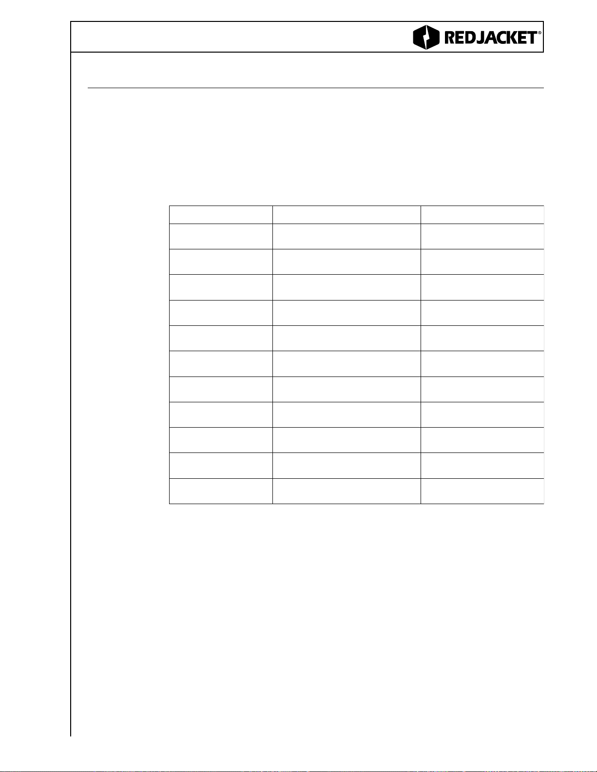
Table A: Specific Gravity and Maximum Viscosity ................................................................................1
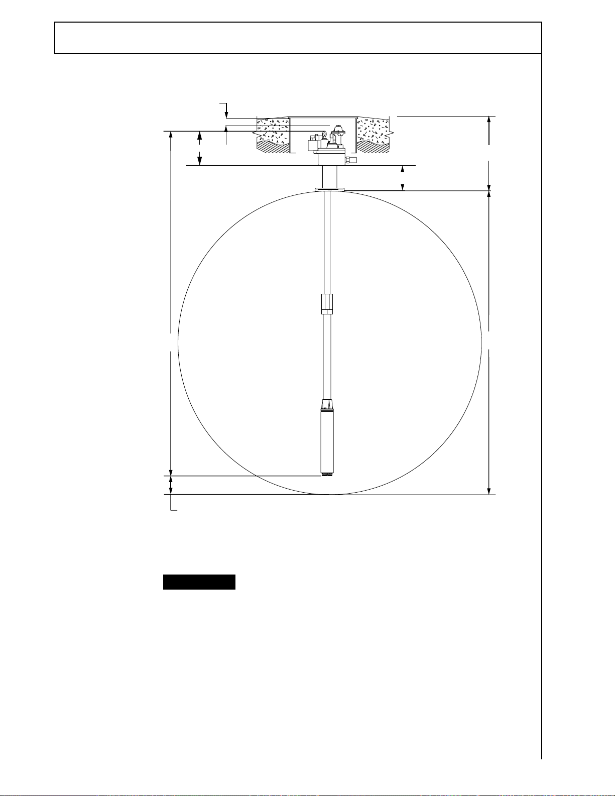
Figure 1.1 Leak Detector and Manifold Dimension ..............................................................................2
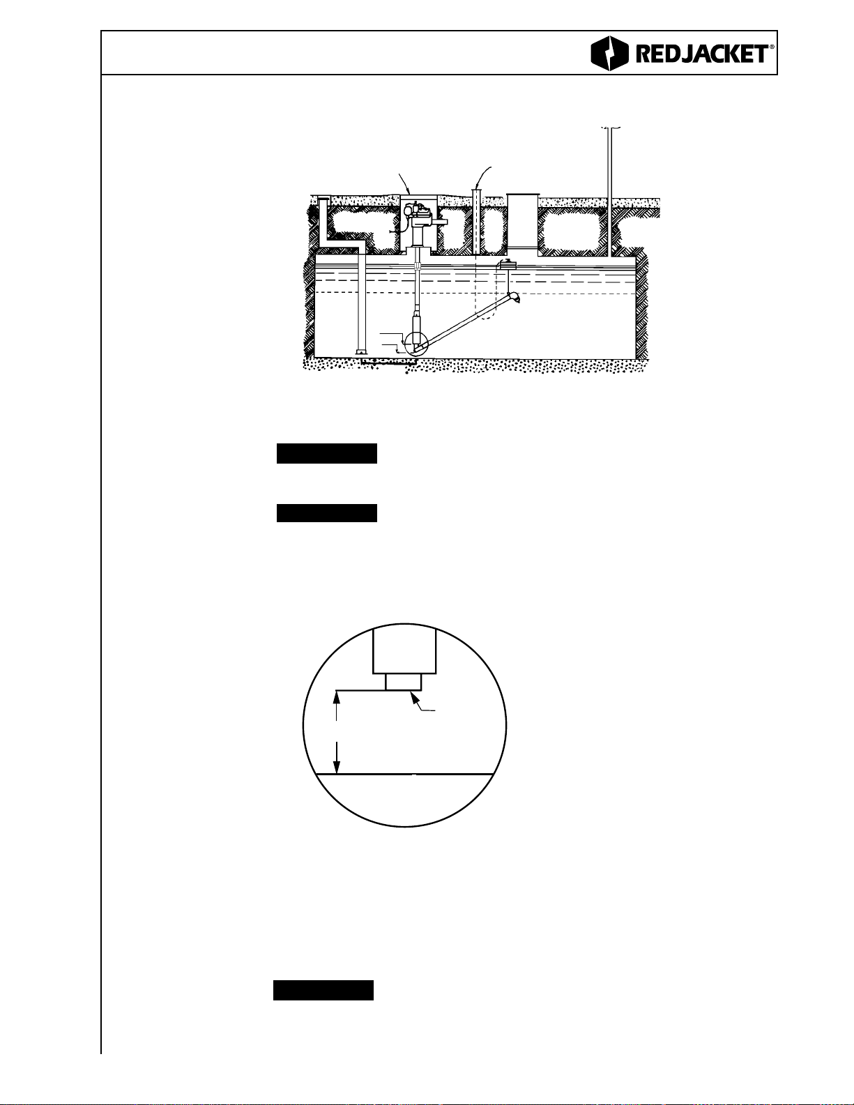
Figure 1.2 Floating Suction Installation ................................................................................................3
Figure 1.3 Floating Suction Adapter......................................................................................................3
Figure 1.4 Measuring the Tank..............................................................................................................4
Table B: Pump Selection ......................................................................................................................5
Table C: Distance from Eye Bolt to Inlet ..............................................................................................6
Table D: Weights and Lengths..............................................................................................................7
Table E: Attaching the UMP ..................................................................................................................9
Figure 2.1 Attaching the UMP............................................................................................................10
Figure 2.2 Aligning the Gasket............................................................................................................10
Figure 2.3 Measuring the Tank............................................................................................................11
Figure 2.4 Loosen the Fittings ............................................................................................................11
Figure 2.5 Adjusting the Pump............................................................................................................12
Figure 2.6 Wiring Schematic ..............................................................................................................13
Figure 2.7 Conduit Box Wiring............................................................................................................13
Figure 2.8 230 VAC Remote Control Box with 110 VAC Coil ............................................................14
Figure 2.9 Suggested Wiring Diagram without Control Box ..............................................................14
Figure 2.10 230 VAC Remote Control Box with 110 VAC Coil and Capacitor....................................15
Figure 2.11 230 VAC Remote Control Box with 230 VAC Coil ..........................................................15
Figure 2.12 Tandem Pumps................................................................................................................16
Figure 2.13 Suggested Wiring for Tandem Pumps ............................................................................16
Figure 2.14 Functional Element ..........................................................................................................18
Table F: Approximate Operating Pressures ........................................................................................19
Figure 3.1 Closing the Check Valve....................................................................................................20
Figure 3.2 Line Test Port ....................................................................................................................20
Figure 4.1 Packer................................................................................................................................21
Figure 4.2 Removing the UMP............................................................................................................22
Figure 4.3 Replacing the Gasket ........................................................................................................22
Figure 4.4 Packer with Functional Element ........................................................................................23
Figure 4.5 Functional Element ............................................................................................................23
Figure 4.6 Loosen the Fittings ............................................................................................................25
Figure 4.7 Adjusting the Pump............................................................................................................25
Figure 4.8 Wiring Schematic ..............................................................................................................26
TABLE OF FIGURES & TABLES
ii

ABOUT THIS MANUAL
This preface describes the organization of this manual, explains symbols and typo-
graphical conventions used, and defines vital terminology. This manual is for personnel
who install Red Jacket submersible pumps for petroleum. It contains the information
required for working in the pit. It also contains a table of figures, a list of abbreviations,
appendixes with the warranty and parts list, and an index.
NOTICE
WARNING
DANGER
CAUTION
The following defined terms are used throughout this manual to bring attention to the
presence of hazards of various risk levels, or to important information concerning use
of the product.
ORGANIZATION
This manual is organized into four chapters:
Chapter 1: Red Jacket Submersible Pump describes the basic components of the
system.
Chapter 2: Installation provides safety notices and gives step-by-step instructions for
installing and wiring the pump, tandem pumps and control boxes. It also describes how
to adjust the Functional Element.
Chapter 3: Testing the installation describes testing the various components of the
system after it has been installed.
Chapter 4: Service and Repair describes how to remove a pump and replace the UMP,
information on replacing the Functional Element, capacitor, and replacement pump
installation instructions.
TYPOGRAPHICAL CONVENTIONS
The various symbols and typographical conventions used in this
manual are described here.
Indicates a tip or reminder.
TERMINOLOGY
Indicates the presence of a hazard that will cause severe per-
sonal injury, death, or substantial property damage if ignored.
Indicates the presence of a hazard that can cause severe per-
sonal injury, death, or substantial property damage if ignored.
Indicates the presence of a hazard that will or can cause minor
personal injury or property damage if ignored.
Indicates special instructions on installation, operation, or
maintenance that are important but not related to personal
injury hazards.
iii

Chassis ground (see also GND)
Earth ground
Ohm, resistance
Microfarad (10-6 farad)
Alcohol-gasoline blends
Centigrade
Domestic
Environmental Protection Agency
Fahrenheit
Fixed Length
Floating Suction Adapter
Foot-pound
Ground
Gallons per hour; Gallons per minute
Horsepower
Hertz
International
International Organization for Standardization
KiloPascals
Millimeter
Newton-meter
National Electrical Code
National Fire Protection Association
National Pipe Thread
Petroleum
Phase
Pounds per square inch; Pounds per square inch gauge
Specific Gravity
Saybolt Seconds Universal, a measure of viscosity
Underwriters Laboratories Inc.
Unit motor pump; Pump-motor assembly
Voltage—alternating current
Volt
Voltage—direct current
Ω
µF
AG
C
DOM
EPA
F
FL
FSA
ft-lb
GND
gph; gpm
hp
Hz
INTL
ISO
kPa
mm
N•m
NEC
NFPA
NPT
Petro
PH
psi; psig
SG
SSU
UL
UMP
VAC
V
VDC
ABBREVIATIONS AND SYMBOLS
iv

CHAPTER 1: RED JACKET 4" SUBMERSIBLE PUMP
OVERVIEW Red Jacket pumps are designed to be compatible with 100% gasoline or diesel. All
UMPs having the model numbers including the AG prefix are designed to be compatible
with 100% gasoline, methanol, ethanol or diesel and 80% gasoline with 20% TAME,
ETBE or MTBE. Single phase pumps are UL listed Class 1, Group D atmosphere.
TABLE A: SPECIFIC GRAVITY AND MAXIMUM VISCOSITY
The Quick-Set feature is an adjustable column pipe and electrical conduit that allows the
overall length to be adjusted to cover a wide range of overall pump lengths. By loosening
a collet on the column pipe, the length of the pump may be varied by extending or
compressing the column pipe.
Four Quick-Set sizes are available, covering most pump length requirements, for precise
lengths, see the sizing charts within this chapter.
ledoMPMUytivarGcificepSmumixaMytisocsiVmumixaM
1R33PMUGA 1R33PMU 59.)C°51(F°06taUSS07
1S57PMUGA 1S57PMU 59.)C°51(F°06taUSS07
1S051PMUGA 1S051PMU 59.)C°51(F°06taUSS07
3-3S57PMUGA 3-3S57PMU 59.)C°51(F°06taUSS07
3-3S051PMUGA 3-3S051PMU 59.)C°51(F°06taUSS07
1S051PMUGA3X 1S051PMU3X 08.)C°51(F°06taUSS07
1S051PMUGA5X 1S051PMU5X 08.)C°51(F°06taUSS07
3S051PMUGA4X 3S051PMU4X 68.)C°51(F°06taUSS07
3-71S57PMUGA 3-71S57PMU 59.)C°51(F°06taUSS07
3-71S051PMUGA 3-71S051PMU 59.)C°51(F°06taUSS07
71S051PMUGA4X 71S051PMU4X 68.)C°51(F°06taUSS07
— 1 —
.95
.95
.95
.95
.95
.80
.80
.86
.95
.95
.86

20"
20"
12"
11"
PUMP
RED JACKET LEAK
DETECTOR
DRIVEWAY
GRADE
ELECTRICAL
CONDUIT BOX
4" RISER
RED JACKET LEAK
DETECTOR
RED JACKET
SUBMERSIBLE
PUMP
20" X 20" MANHOLE RED JACKET
LEAK DETECTOR
RED JACKET
SUBMERSIBLE PUMP
2" OUTLET
TO DISPENSERS
TANK
Figure 1.1 Leak detector and manifold dimensions
TANK
FLEX
CONNECTOR
LEAK DETECTOR INSTALLATION AND MANIFOLD DIMENSIONS
6”
8”
10”
13”
5.5”
— 2 —
4” Petroleum & AG
3
4

•Easy service access is provided by unbolting manhole lid through which pump is
mounted and removing entire assembly. Use proper thread sealant and insert gas-
ket between flanges of floating suction and pump. This prevents hindrance to pump
performance when product level is below this point.
Red Jacket pumps are centrifugal type pumps and as such
are not designed to pump product when the level is below the
bottom end of the UMP.
14" APPROX.
4" APPROX.
OPENING FOR GAUGING AND
ADJUSTING CABLE
MANHOLE:
SHOULD BE LARGER THAN MANHOLE
WELDED ON TANK. KEEP AREAOPEN
DOWN TO TANK.
NOTICE
NOTICE
Figure 1.2 Floating suction installation
RECOMMENDED FLOATING SUCTION INSTALLATION
Distance between center line of pump motor and center line
of bottom fill tube should be 3’ minimum. Air locking of pump
after product delivery may occur at distances less than this.
We supply adapter only; not the apparatus. Floating suction
adapter is not available for the X5 Model pump.
•The floating suction arm can be mounted to pump previous to installing in tank.
See example of adaptation to floating suction assembly below.
Figure 1.3 Floating Suction Adapter
2" N.P.T.
FEMALE
THREAD
14"
BOTTOM OF THE TANK
NOTICE
— 3 —

Figure 1.4 Measuring the tank (See TABLE B for adjustment range.)
DIMENSIONS FOR PUMP SELECTION
NOTICE Distance between center line of pump motor and center line
of bottom fill tube should be 3’ minimum. Air locking of pump
after product delivery may occur at distances less than this.
11"
5" STANDARD INLET ANDTRAPPER
14" FOR FLOATING SUCTION ADAPTER
4" min.
A
D
C
B
— 4 —
4” Petroleum & AG

— 5 —
TABLE B: DISTANCE
SPECIFICATIONS
TELNIOTTLOBEYEMORFECNATSID
#LEDOMDESSERPMOCDEDNETXE
nimmnimm
1T1R33PGA,1T1R33P0.8672710.592142
2T1R33PGA,2T1R33P0.1911320.5214713
3T1R33PGA,3T1R33P0.52147130.2916784
4T1R33PGA,4T1R33P0.52147130.9518304
1T1S57PGA,1T1S57P5.0739715.799742
2T1S57PGA,2T1S57P5.3977325.7211423
3T1S57PGA,3T1S57P5.72114235.4913494
4T1S57PGA,4T1S57P5.72114235.1614014
1T1S051PGA,1T1S051P5.3756815.0011552
2T1S051PGA,2T1S051P5.6905425.0313133
3T1S051PGA,3T1S051P5.03131335.7915105
4T1S051PGA,4T1S051P5.03131335.4617714
1T1S051PGA3X,1T1S051P3X5.4778815.1013752
2T1S051PGA3X,2T1S051P3X5.7917425.1315333
3T1S051PGA3X,3T1S051P3X5.13153335.8917305
4T1S051PGA3X,4T1S051P3X5.13153335.5619914
1T1S051PGA5X,1T1S051P5X0.4823120.1117182
2T1S051PGA5X,2T1S051P5X0.70161720.1419753
3T1S051PGA5X,3T1S051P5X0.14197530.8021825
4T1S051PGA5X,4T1S051P5X0.14197530.5713444
1T3-3S57PGA,1T3-3S57P0.3735810.0019352
2T3-3S57PGA,2T3-3S57P0.6973420.0311033
3T3-3S57PGA,3T3-3S57P0.03110330.7913005
4T3-3S57PGA,4T3-3S57P0.03110330.4615614
1T3-3S051PGA,1T3-3S051P0.5770910.2012952
2T3-3S051PGA,2T3-3S051P0.8919420.2314533
3T3-3S051PGA,3T3-3S051P0.23145330.9916505
4T3-3S051PGA,4T3-3S051P0.23145330.6618124
1T3S051PGA4X,1T3S051P4X5.5702915.2016062
2T3S051PGA4X,2T3S051P4X5.8940525.2318633
3T3S051PGA4X,3T3S051P4X5.23186335.9913705
4T3S051PGA4X,4T3S051P4X5.23186335.6612324
1T3-71S57PGA,1T3-71S57P0.2782810.994152
2T3-71S57PGA,2T3-71S57P0.5921420.9216723
3T3-71S57PGA,3T3-71S57P0.92167230.6917794
4T3-71S57PGA,4T3-71S57P0.92167230.3619314
1T3-71S051PGA,1T3-71S051P0.4787810.1014652
2T3-71S051PGA,2T3-71S051P0.7926420.1316233
3T3-71S051PGA,3T3-71S051P0.13162330.8918205
4T3-71S051PGA,4T3-71S051P0.13162330.5619814
1T71S051PGA4X,1T71S051P4X5.4729815.1018752
2T71S051PGA4X,2T71S051P4X5.7967425.1310433
3T71S051PGA4X,3T71S051P4X5.13104335.8911405
4T71S051PGA4X,4T71S051P4X5.13104335.5613024

— 6 —
4” Petroleum & AG
TABLE C: ELECTRICAL SERVICE INFORMATION
Required power supply rating for 60HZ, 1 phase motors is 208-230VAC. For 50HZ 1 phase motors, required rating is 220-240VAC,
3 phase motors required rating is 380-415 VAC.
NOITAMROFNIECIVRESLACIRTCELE
PMU ledoM .oN PHZHHP
egatloV noitautculF egnaR
daoL.xaM spmA rotoRdekcoL spmA
)smhO(ecnatsiseRgnidniW )smhO(ecnatsiseRgnidniW roticapaC )Fµ(tiK
.niM.xaMwolleY-kcalBwolleY-deRdeR-kcalB
1R33PMUGA 1R33PMU 3/10610020520.40.319.9-1.83.91-8.513.92-8.32)5.71(5-422-441
1S57PMUGA 1S57PMU 4/30610020525.60.223.3-7.20.81-7.414.12-3.71)5.71(5-422-441
1S051PMUGA 1S051PMU 2/1-10610020525.010.243.2-8.15.6-3.59.8-2.6)52(5-522-441
1S051PMUGA3X 1S051PMU3X 2/1-10610020525.010.243.2-8.15.6-3.59.8-2.6)52(5-522-441
1S051PMUGA5X 1S051PMU5X 2/1-10610020525.010.243.2-8.15.6-3.59.8-2.6)52(5-522-441
PMU ledoM .oN PHZHHP
egatloV noitautculF egnaR
daoL.xaM spmA rotoRdekcoL spmA )smhO(ecnatsiseRgnidniW roticapaC )Fµ(tiK
.niM.xaMkcalB-eulBkcalB-nworBnworB-eulB
3-3S57PMUGA 3-3S57PMU 4/30510020528.56.813.4-5.33.82-1.327.23-5.62)5.71(5-422-441
3-3S051PMUGA 3-3S051PMU 2/1-10510020520.015.434.3-7.22.51-4.217.81-0.51)52(5-522-441
3S051PMUGA4X 3S051PMU4X 2/1-10510020520.015.434.3-7.22.51-4.217.81-0.51)52(5-522-441
3-71S57PMUGA 3-71S57PMU 4/30532437542.20.119.13-1.629.13-1.629.13-1.62---
3-71S051PMUGA 3-71S051PMU 2/1-10532437548.38.518.41-1.218.41-1.218.41-1.21---
71S051PMUGA4X 71S051PMU4X 2/1-10532437548.38.518.41-1.218.41-1.218.41-1.21---

— 7 —
The weights and lengths listed above are
approximate values and will vary due to
manufacturing tolerances.
The optional Trapper inlet screen is available
as a field installed accessory. The field installed
option adds 3.625 inches (92 mm) to the listed
values. For installation instructions see Red
Jacket literature for #051-256-1. For models
with floating suction adapter, add 2.375 inches
(59 mm) and 4 lbs (1.8 Kg).
TABLE D: WEIGHTS AND LENGTHS
LEDOMPMUPHHTGNELTHGIEW
nimmblgk
1S33PMUGA 1S33PMU 3/151083420.11
1S57PMUGA 1S57PMU 4/32/171744827.21
1S051PMUGA 1S051PMU 2/112/102915435.51
1S051PMUGA3X 1S051PMU3X 2/114/112145538.51
1S051PMUGA5X 1S051PMU5X 2/1113587832.71
3-3S57PGA4/3027055.039.31
3-3S051PGA2/114/122065435.51
3S051PGA4X2/114/322675539.51
3-71S57PGA4/391284827.21
3-71S051PGA2/1112235131.41
71S051PGA4X2/112/112745235.41
NOTICE
NOTICE
R1
R1

— 8 —
4” Petroleum & AG

— 9 —
CHAPTER 2: INSTALLATION
INSTALLATION SAFETY NOTICES
ATTENTION INSTALLER: Read this important safety information before beginning work.
This product operates in the highly combustible atmosphere
of a gasoline storage tank. To protect yourself and others
from serious injury, death, or substantial property damage,
carefully read and follow all warnings and instructions in
this manual.
Failure to follow all instructions in proper order can cause
personal injury or death. Read all instructions before beginning
installation. All installation work must comply with the latest
issue of the National Electrical Code (NFPA 70), the Automotive
and Marine Service Code (NFPA 30A), and any national, state,
and local code requirements that apply.
Only trained and qualified personnel may install, program, and
troubleshoot Red Jacket equipment. Hazards can cause severe
personal injury, death, or substantial property damage if
ignored.
Before installing pipe threads apply an adequate amount of
fresh, UL Classified for petroleum, Non-setting thread sealant.
WARNING
DANGER
WARNING
WARNING
TABLE E: ATTACHING THE UMP
dlofinaM/rekcaPPMU
1R33PGA 1R33P 1R33PMUGA 1R33PMU
1S57PGA 1S57P 1S57PMUGA 1S57PMU
1S051PGA 1S051P 1S051PMUGA 1S051PMU
1S051PGA3X 1S051P3X 1S051PMUGA3X 1S051PMU3X
1S051PGA5X 1S051P5X 1S051PMUGA5X 1S051PMU5X
3-3S57PGA 3-3S57P 3-3S57PMUGA 3-3S57PMU
3-3S051PGA 3-3S051P 3-3S051PMUGA 3-3S051PMU
3S051PGA4X 3S051P4X 3S051PMUGA4X 3S051PMU4X
3-71S57PGA 3-71S57P 3-71S57PGA 3-71S57PMU
3-71S051PGA 3-71S051P 3-71S051PMUGA 3-71S051PMU
71S051PGA4X 71S051P4X 71S051PMUGA4X 71S051PMU4X
ATTACHING THE UMP
The UMP is identified by a model number marked on the shell. The Packer/Manifold
assembly with attached piping is identified by the catalog number on the capacitor cover
nameplate. The catalog number will be followed by T1, T2, T3, or T4 on adjustable
length pumps or a four digit number indicating the original pump length in feet and inches
(a 9 ft. 6 inch pump would have 0906 after the model number.)

Figure 2.2 Aligning the gasket
PACKER/MANIFOLD
WITH PIPING
UMP
KIT (144-328-4)
Figure 2.1 Attaching the UMP
The attachment hardware kit to be used to connect the UMP to the Packer/Manifold
assembly piping consists of four Grade 8 5/16-18 socket head cap screws, four 5/16
spring lock washers, and one discharge head gasket. It is identified by the kit number
144-328-4 marked on the bag.
Suggested tools (non-sparking): 3/4” wrench, pipe wrench,
1/4” allen wrench, 9/16” wrench, screw driver, wire cutter and
wire stripper.
1: Place the new gasket on the new UMP so that all the holes align.
Gaskets from competitive UMPS will not seal properly and
performance will be reduced.
Visually inspect the pigtail connector in the discharge head.
Replace if damaged. Be certain the indexing tab of the pigtail
is seated in the notch of the discharge head.
2: Lubricate the o-ring and pigtail with petroleum based jelly.
3: Align the UMP positioning dowel and boss with the proper holes in the discharge
head and push the UMP into position using hand force only. The UMP should be
snug against the discharge head prior to installing the UMP retaining bolts.
Use hand force to put the UMP on the discharge head. If the
UMP does not seat properly, snug against the discharge head,
remove the UMP and correct the problem.
Do not use the bolts to pull the UMP into position. Use the
cross pattern to snug and torque bolts. Do not over torque the
bolts. Not following these instructions may cause parts to fail.
4: Install the UMP retaining bolts and lock washers. Snug and then torque the bolts
using a cross pattern. Torque to 7 ft-lb. (11 N•m).
INSTALLING THE PUMP
Red Jacket petroleum pumps are designed to operate in
Class 1, Group D locations.
NOTICE
NOTICE
NOTICE
— 10 —
4” Petroleum & AG
CAUTION
NOTICE

Figure 2.3 Measuring tank
Specifications and installation instructions may change if
the manufacturer recommends changes.
The product temperature must not exceed 105°F (41°C)
because the thermal overload protectors in the submersible
motors may trip.
To Install Quick-Set Pump: For Fixed Length Pump Go to Step 7
1: Install the riser pipe into the 4-inch tank opening. Use thread sealant. Tighten the
riser pipe in the tank until watertight.
2: Measure the distance from the bottom of the tank to the top of the 4-inch riser
pipe shown in figure 2.3.
3: Uncoil the pigtail and lay it flat so it will feed into the packer without knotting
or kinking.
4: Loosen the clinch assembly, starting by loosening the set screw in the side of the
locking nut, then loosen the locking nut.
Figure 2.4 Loosen fittings
— 11 —
NOTICE
NOTICE

— 12 —
4” Petroleum & AG
Take care not to damage the pigtail. If pump is to be adjusted
shorter, tension must be kept on pigtail to eliminate kinking.
6: Tighten locking nut and torque to 150 ft-lb (200 N•m) minimum, then torque the set
screw to 30-35 in-lb (3.5 – 4 N•m).
Return line should be installed on every application to insure
against nuisance trips of electronic tank monitoring.
7: Attach tubing to barbed fitting, secure with clamp.
8: Lay tubing beside column pipe. Cut off 1-3 inches (25-76 mm) above the
discharge head.
9: Secure tube to column pipe with tie straps. Locate tie straps approximately 6 inches
(152 mm) from packer, 6 inches (152 mm) from discharge head and middle of tubing.
10: Install the pump onto the riser pipe using thread sealant while making the proper
alignment of the manifold and piping. Tighten the manifold until watertight.
For fixed length pump, skip to conduit box wiring
11: Remove cover from wiring compartment.
12: Pull pigtail wires into wiring compartment.
13: Cut pigtail wires extending approximately 8-inches (200 mm) out of
wiring compartment.
14: Strip back insulation of all wires 3/8-inch (10 mm).
15: Using supplied wire nuts, attach like colored pump pigtail wires to wires.
See figure 2.6 to verify connections.
NOTICE
NOTICE
Figure 2.5 Adjust pump length
5: Pull the UMP end until the distance between the bottom of the manifold and the
of the UMP is 5 inches (125 mm) (14 inches (356 mm) for floating suction) shorter
than the distance measured in step 2 (see figure 2.5)
If UMP is equipped with floating suction adapter, see
recommended floating suction installation in Chapter 1.
NOTICE

— 13 —
16: Install excess wire into wiring compartment. Replace wiring compartment cover.
Torque to 35 ft lb (50 N•m). Thread sealant should not be used.
17: Install eyebolt plug, use approved non-setting thread sealant and torque to
50 ft lb (70 N•m).
CONDUIT BOX WIRING
ALWAYS DISCONNECT and LOCK or TAG OUT the power
before starting to service the pump.
1: Connect electrical conduit through approved fittings to conduit box.
2: Remove cover from conduit box.
3: Connect wires from power supply to wires in the conduit box. Install ground wire as
shown if applicable. Replace cover, do not use thread sealant on dual box. Thread
sealant required on single box.
Figure 2.6 Wiring schematic
ORANGE
BLACK
CAPACITOR
ORANGE
BLACK
RED
IN FROM
ELECTRICAL
CONNECTOR
OUT TO
PUMP PIGTAIL
Figure 2.7 Conduit box wiring
ELECTRICAL
CONNECTOR ASSY.
GREEN GROUNDING
SCREW
GROUND WIRE
CUP WASHER
TERMINAL
EXTERNAL TOOTH
LOCK WASHER
POWER LEADS
TO PUMPS
CONDUIT BOX
CONDUIT
DUAL BOX
SINGLE BOX
CONDUIT
ELECTRICAL
CONNECTOR ASSY.
GREEN GROUNDING
SCREW
GROUND WIRE
CUP WASHER
TERMINAL
EXTERNAL TOOTH
LOCK WASHER
POWER LEADS TO
PUMP
CONDUIT BOX
DANGER

— 14 —
4” Petroleum & AG
CONTINUOUS
DUTY
CAPACITOR
SUGGESTED WIRING DIAGRAM WITHOUT OPTIONAL CONTROL BOX
DISPENSER
LIGHTING
FROM
SEPARATE
CIRCUIT
115 VOLT
EXT PILOT
LIGHT BY
CONTRACTOR
WIRING TROUGH
INHERENT
OVERLOAD
PROTECTOR
2 POLE DISPENSER SWITCHES
MAKE GROUND CONNECTION
IN ACCORDANCE WITH LOCAL
CODES
15 AMP 3 POLE
SWITCH
(N.E.C. REQUIRES
DISCONNECT
BREAK
ALL WIRES TO
DISPENSERS)
PUMP
JUNCTION
BOX PACKER
LOAD CENTER 230V 1Ø 3 WIRE
Figure 2.8
Figure 2.9
230 VAC REMOTE CONTROL BOX WITH 110 VAC COIL
UL LISTED, RED JACKET MODEL 880-041-5
COMBINATION OF 2 POLE DISPENSER SWITCHES OR EXTERNAL PILOT LIGHT.
• RATED FOR TWICE THE FULL LOAD CURRENT OF THE MOTOR:
1/3 HP-8 AMPS, 3/4 HP-13 AMPS, 1-1/2 HP-21 AMPS
• RATED FOR HANDLING LOCKED ROTOR CURRENT OF THE MOTOR:
1/3 HP-13 AMPS, 3/4 HP-22 AMPS, 1-1/2 HP-42 AMPS
LINE STARTER
PILOT LIGHT
L2 L1
LOAD CENTER
208 OR 230 VOLT
1 PHASE, 3 WIRE
15A-2P SWITCHED
NEUTRAL BREAKER
OPTIONAL
OTHER
DISPENSER
(MAX. TOTAL
OF 6
DISPENSERS)
EXTERNAL
PILOT LIGHT
(115 VOLTS)
25 WATT MAX.
MOTOR
3 P.S.T. TOG-
GLE SWITCH
WIRING
TROUGH
JUNCTION
BOX IN
MANIFOLD
DISPENSER LIGHTS
ELECTRICAL
INTERLOCK
OPTIONAL
SOLENOID
VALVE (76 VOLT AMPS. MAX)
DISPENSER
PACKER
CONTINUOUS
DUTY
CAPACITOR
N
INTERNAL
OVERLOAD
PROTECTOR
15A-3P SWITCHED
NEUTRAL BREAKER
P
MAKE GROUND
CONNECTION IN
ACCORDANCE WITH
LOCAL CODES
This manual suits for next models
22
Table of contents