AccuDome ACD-1000-LG27 User manual

INSTRUCTION MANUAL Ver 3.0
Indoor Pan, Tilt and Zoom Dome Camera / ACD-1000-LG27

2
P
an,
T
ilt and Zoom Dome Camera / ACD-1000-LG2
7
1
Introduction
Features 3
Components 4
System Configuration 5
2RS485 and PTZ Basics
Physical Connection 6
Multiple PTZ Setup 7
ID, Protocol, Baud Rate 9
3 Installation
Ceiling Mount 10
4 Camera Addressing
Camera Address Setting 11
Protocol and Baud Rate Settings 13
5 Basic Functions
Selecting Camera 14
Setting Presets 15
Calling Presets 15
Clearing Presets 15
Auto Cruise 16
Auto Pan 16
6 Advanced Functions
Camera Power 17
Back Light Compensation 17
Digital Zoom 17
Focus Mode 17
Iris Mode 18
White Balance Mode 18
7 On Screen Display
Main Menu 19
Focus Set 20
Auto White Balance 20
Auto Exposure 21
Special Functions 21
Motion Detection 22
Function On Screen Display 22
8 Parts Description and Function 23
9 Product Specifications 24

3
P
an,
T
ilt and Zoom Dome Camera / ACD-1000-LG2
7
Camera Specification
•Sony Module 480 Lines
•27X Optical Zoom
•10X Digital Zoom
•3.25mm – 88mm Zoom
•IR Sensitive
•12V DC
Complete View
•360 Degree Pan, 90 Degree Tilt. For No Blind Spots
Housing
•Indoor Use Only
•Multiple Mounting Configurations
•Operating Temperatures: 32° to 104° F
PTZ Control
•RS-485 Communication, MAX 31 Multi-drop
•Versatile Pelco-D and Pelco P Protocol
•Variable Pan and Tilt Speed
•64 Programmable Presets
•OSD Setup
•Programmable Cruise Sequence
Introduction 1
Features

4
P
an,
T
ilt and Zoom Dome Camera / ACD-1000-LG2
7
Parts Information
Item Part No. Description
Dome Camera and Housing ACD-1000-LG27 NTSC Dome Camera, Indoor Housing, Including Transparent Dome
Power Supply 12v DC 2.5A Power Supply
Manual Manual for ACD-1000-LG27
Default Components
Dome Camera and Housing Accessories
ACD-1000 Manual
Power Supply
Components
Introduction 1

5
P
an,
T
ilt and Zoom Dome Camera / ACD-1000-LG2
7
Configuration
Part Description
System Configuration
INTRODUCTION 1
INTRODUCTION 1
Introduction 1
Video Output
BlueNet Video server BlueNet Video server
DVR DVR
PTZ Controller Monitor
RS-485 Input
1. Mounting Base
2. Outer Tube
3. Shading Cover
4. Outer Cover
5. Camera
6. Connecting Cable

6
P
an,
T
ilt and Zoom Dome Camera / ACD-1000-LG2
7
RS-485 communication
RS-485 communication is used to control a PTZ camera. Standalone DVRs, PC-based DVRs,
keyboard joystick PTZ controllers, video servers, and a variety of other CCTV equipment usually have
an RS-485 interface (push terminals, D-Sub connector, etc.) for PTZ control. The CCTV equipment
transmits control signals while the PTZ camera receives the signals and performs the function
required.
RS-485 utilizes two wires; a ‘+’ wire and a ‘–’ wire. These two wires may also be label or
reference as:
•+ and –
•D+ and D-
•A+ and B-
•RS485+ and RS485-
To make the physical connection from the controlling device (DVR, keyboard controller, etc.) to
the PTZ, simply connect the RS485 ‘-’ from the controlling device to the RS485 ‘-’ on the PTZ. Do the
same for the RS485 ‘+’. Any type of wire can be used for the connection, but 0.56mm (24AWG)
twisted pair is recommended.
+ +
- -
PTZ Physical Connections
Controller
PTZ and RS-485 Basics 2
Physical Connection
Continued on Next Page

7
P
an,
T
ilt and Zoom Dome Camera / ACD-1000-LG2
7
Baud Rate is the data transmission rate in bps (bits per second). Both the controlling device and
PTZ must use the same baud rate. Most PTZ camera and devices default to a baud rate of 2400 bps.
The maximum theoretical transmitting distances of RS-485 are below using 0.56mm (24AWG)
twisted pair cable.
Baud Rate Maximum Distance
2400 bps 1800m
4800 bps 1200m
9600 bps 800m
If thinner cables are used or the dome is installed in an environment with strong electromagnetic
interference or many PTZs are used on the same line, the maximum distance will be decreased.
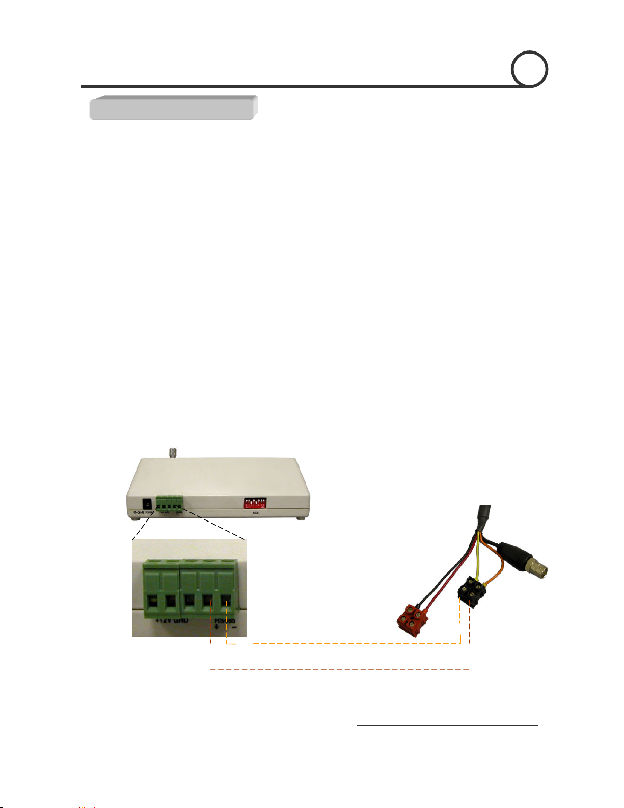
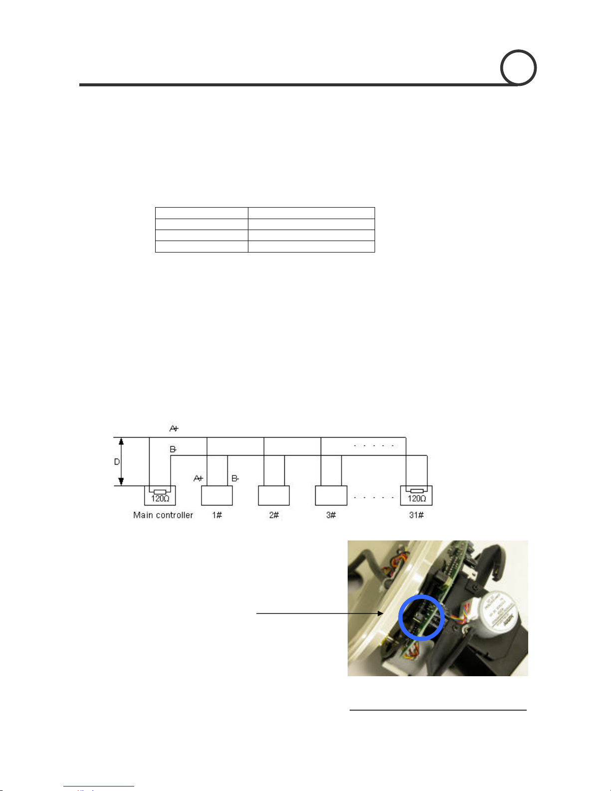
For multiple PTZ installs, RS485 standards require a daisy-chain connection between the
equipment. Up to 32 devices, including the controller can be daisy-chained. A 120 Ω termination
must be made on the first and last device in the chain. Most controllers are already terminated. To
terminate the last PTZ in line, simply locate the 120 Ωtermination resistor jumper on the PTZ’s
protocol PCB and set the jumper to pins 1 & 2. By default, the PTZ is not terminated, thus having
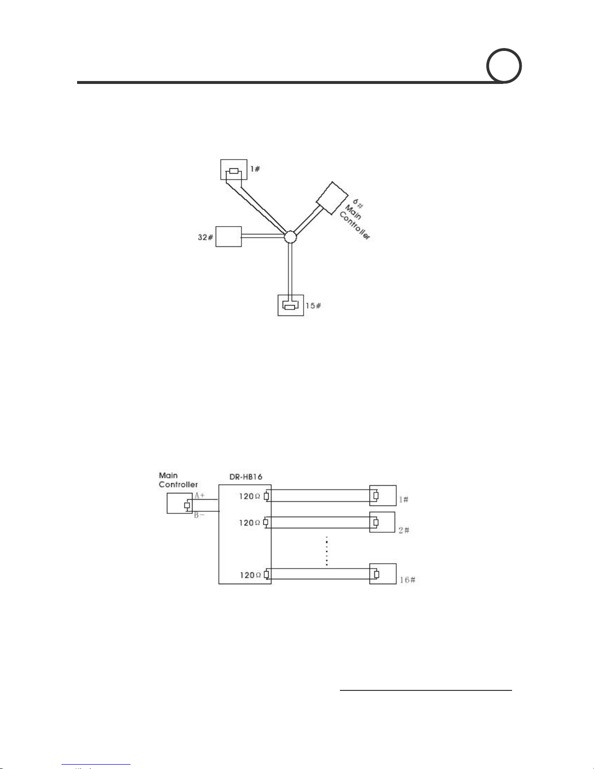
the pins on 2 & 3. For Star Configurations, see the next page.
Termination Jumper Location.
Continued on Next Page
2

8
P
an,
T
ilt and Zoom Dome Camera / ACD-1000-LG2
7
Multiple PTZ (cont.)
Some circumstances require the use of a star configuration. The termination resistors must be set on the
two devices that are the farthest distances away from each other, in this case #1 and #15 as seen below.
As the star configuration does not conform to the RS485 standards, problems such as signal reflection
and lower anti-interference performance arise when the cable runs are long. In addition, the reliability of
control signals are decreased which may cause the PTZ to respond intermittently, not respond at all, or
operate a single command continuously without ever stopping. In these circumstances, the factory
recommends the use of an RS485 distributor (DR-HB16). The distributor can change the star
configuration connection to the mode of connection stipulated in the RS485 standards. With the
distributor, reliable data transmission can be received.
PTZ and RS-485 Basics
2

9
P
an,
T
ilt and Zoom Dome Camera / ACD-1000-LG2
7
PTZ Addressing and Communication Protocol
Before installing PTZs, you must understand 3 things:
-PTZ Camera ID
-PTZ Protocol
-PTZ Baud Rate
PTZ Camera ID - Each PTZ camera in an install must have a unique ID number assigned. Most
PTZs default to ID#1. The PTZ controller must be told what PTZ camera to
control, and this ID number is called to control the corresponding camera. The
PTZ ID number can be set to any number 1 – 1023.
PTZ Protocol - All PTZ controllers and cameras need to support a common communication
language in order to send/receive control commands. This language is called a
protocol. The protocol set in the PTZ camera must match the protocol set in the
controller. Below is a list of commonly supported protocols.
•Pelco-D
•Pelco-P
•Santachi
•Hunda600
•Longcomity
PTZ Baud Rate - Baud Rate is the data transmission rate in bps (bits per second). Both the
controlling device and PTZ must use the same baud rate. Most PTZ cameras and
devices default to a baud rate of 2400 bps.
PTZ and RS-485 Basics 2

10
P
an,
T
ilt and Zoom Dome Camera / ACD-1000-LG2
7
Ceiling Mount Installation using Indoor Housing Assembly
1. Remove Mounting Base from
dome and mount to ceiling
2. Remove the Outer Tube from the
three screws located on top of the
Outer Tube, underneath the
Mounting Base, to set DIP
switches according to Protocol,
Baud rate, and Camera ID
desired. (See page 11 for details)
System Installation
INSTALLATION 3
INSTALLATION
INSTALLATIONInstallation

11
P
an,
T
ilt and Zoom Dome Camera / ACD-1000-LG2
7
RS-485 communication
RS-485 communication is used to control the camera. RS-485 utilizes two wires, + and -. Protocol,
Baud rate and Camera Address are also required and are set using 2 sets of Dip Switch sets under the
data board, accessed by removing the Outer Tube (see page 10). Each camera connected to the PTZ
controller must have a unique address.
•Specification Standard RS-485 with MAX. 31 Camera Control
•Number of wire 2 Wire (D+, D-)
•Protocol Pelco-D, Pelco-P, A01, B01, Santachi, Longcomity and HUNDA600
SW 1 : Camera Address Settings
ON
1 2 3 4 5 6 7 8 9 10
SW1
DIP # 1 2 3 4 5 6 7 8 9 10
Value 1 2 4 8 16 32 64 128 256 512
SW1:Address Setting (1~1023)
Camera Addressing
•Factory Default ID is 1
•The dip switches are equivalent to 10-
b
it
b
inary. Examples are listed on the next
page.
Dipswitch
SW1
Dipswitch
SW2
4
Camera Addressing

12
P
an,
T
ilt and Zoom Dome Camera / ACD-1000-LG2
7
SW 1 : Camera Address Settings (continued)
When using more than 1 RS-485 device each unit must be given a unique address. Refer to the
chart on the previous page for the value of each dip switch. For each dip switch that is ON the
value/values are added together, the total is the address of that unit.
For Example:
For an address of 1:
Dip switch #1 (value = 1) will be ON all others OFF
For an address of 5:
Dip switch #1 (value = 1) & #3 (value = 4) will be ON all others OFF
For an address of 157:
Dip Switch #1 (value = 1), #3 (value = 4), #4 (value = 8), #5 (value = 16), #8 (value =
128) will be ON all others OFF
4
Camera Addressing

13
P
an,
T
ilt and Zoom Dome Camera / ACD-1000-LG2
7
SW 2 : Camera Protocol and Baud Rate Settings
This camera supports multiple RS-485 Protocols and Baud Rates which can be set using the SW2
Dip switch located under the data board, accessed by removing the Outer Tube (see page 10).. The table
below contains a list of protocols supported by the camera and the default baud rate for the protocol.
Selection Of Protocols Default Baud
Rates
Supported
Protocol 1st 2
nd 3
rd 4
th 5
th 6
th
Pelco D /2400 ON ON OFF OFF OFF OFF
Pelco P /4800 OFF OFF ON OFF ON OFF
Pelco P /9600 OFF OFF ON OFF OFF ON
A01 OFF OFF OFF OFF ON OFF
B01 ON OFF OFF OFF OFF ON
Santachi OFF ON OFF OFF OFF ON
Longcomity OFF ON ON OFF OFF ON
Hunda600 ON ON ON OFF OFF ON
Dip Switch settings for configuring the camera to use Pelco D Protocol at 2400 Baud:
Below is a table showing the proper settings of the 5th and 6th dip switch on SW2 for setting
preferred baud rate to match that of the PTZ controller.
Selection Of Protocols Baud Rates
Baud Rate 1st 2
nd 3
rd 4
th 5
th 6
th
2400 OFF OFF
4800 ON OFF
9600 OFF ON
19200 ON ON
4
Camera Addressing

14
P
an,
T
ilt and Zoom Dome Camera / ACD-1000-LG2
7
Once initial control of the PTZ has been established by correctly connecting RS-485, setting matching
protocol and baud rate in the PTZ and controller, and the user is able to pan, tilt, and zoom additional
features can be utilized.
All Basic Functions such as setting presets, calling presets, clearing presets, enabling auto cruise (tour),
setting auto pan, enable auto pan are listed in this section. Any PTZ controlling device can enable these
functions IF the controlling device supports at least 64 presets. Examples have been given below for
operation using the KCT-100 and KCT-2500 keyboard joystick controllers.
*NOTE* In the following operational description, the capital letter N represents the
number you wish to set.
Selecting the Camera
•KCT-100: [N] + [CAM]
Ex: To select camera 1, simply press 1, then CAM
•KCT-2500: [CAM] + [N] + [ENTER]
Ex: To select camera 1, simply press CAM, then 1, then Enter
**If successful, the Camera ID you have chosen will be shown on the controller display
Basic Functions
Basic Functions
FUNC
0
123
456
789
Enter
Clear
WI DE TEL E FAR NEAR
CAM AUT O OPEN CL OSE
Current CamID:001
ON OFF F1 F2 F3
CALL PRESET SHOT
Speed Dome Cont r ol l er
LI VE TAPE SEQ SWITCH
KCT-100 Controller KCT-2500 Controller
5

15
P
an,
T
ilt and Zoom Dome Camera / ACD-1000-LG2
7
Setting a Preset Position
•KCT-100: [N] + [PRESET]
Ex: To set preset 1, simply press 1, then PRESET
•KCT-2500: [PRESET] + [N] + [ENTER]
Ex: To set preset 1, simply press PRESET, then 1, then ENTER
**There will be no notification of successfully setting the preset. Move the controller and
call the newly set preset to ensure the preset was saved.
Calling a Preset Position
•KCT-100: [N] + [CALL]
Ex: To call preset 1, simply press 1, then CALL
•KCT-2500: [CALL] + [N] + [ENTER]
Ex: To call preset 1, simply press CALL, then 1, then ENTER
**If successful, the camera will move to the specified preset position
Clear or Delete a Preset
•KCT-100: [N] + [CLEAR]
Ex: To clear preset 1, simply press 1, then CLEAR
•KCT-2500: [PRESET] + [N] + [OFF]
Ex: To clear preset 1, simply press PRESET, then 1, then OFF
** There will be no notification of successfully clearing the preset. Move the controller and
call the preset to ensure that no movement occurs, signifying a successful clear.
5
Basic Functions

16
P
an,
T
ilt and Zoom Dome Camera / ACD-1000-LG2
7
Auto Cruise (Tour)
•KCT-100: [51] + [PRESET]
Ex: To enable auto cruise, simply press 51, then PRESET
•KCT-2500: [PRESET] + [51] + [ENTER]
Ex: To enable auto cruise, simply press PRESET, then 51, then ENTER
** Auto Cruise continuously scans from presets 1 – 16 in sequence. You must have
presets 1-5 set before running the Auto Cruise.
Auto Pan
•KCT-100: Set Start Point: [52] + [PRESET]
Set End Point: [53] + [PRESET]
RunAuto Pan Low Speed: [51] + [CALL]
RunAuto Pan Med Speed: [52] + [CALL]
RunAuto Pan Max Speed: [53] + [CALL]
Ex: After setting the start point and end point of the auto pan, simply
press 53, then CALL to start the auto pan in max speed
•KCT-2500: Set Start Point: [PRESET] + [52] + [ENTER]
Set End Point: [PRESET] + [53] + [ENTER]
RunAuto Pan Low Speed: [CALL] + [51] + [ENTER]
RunAuto Pan Med Speed: [CALL] + [52] + [ENTER]
RunAuto Pan Max Speed: [CALL] + [53] + [ENTER]
Ex: After setting the start point and end point of the auto pan, simply
press CALL, then 53, then ENTER to start the auto pan in max
speed
5
Basic Functions

17
P
an,
T
ilt and Zoom Dome Camera / ACD-1000-LG2
7
All of the Advanced Functions of this camera are controlled by calling and setting specific presets to
enable and disable the functions. This includes the OSD (On Screen Display) Setup on page 21. Your PTZ
controller must be able to call and set presets 51 through 63 to be able to access the Advanced Functions
of this camera.
Camera Power:
The CAMERA POWER feature allows you to power the camera ON or OFF remotely.
Function Action on Controller
Camera POWER ON Call preset 54
Camera POWER OFF Set preset 54
Back Light Compensation:
Back Light Compensation allows the camera to compensate for bright lights in the picture. You can
set the BLC ON or OFF manually by using the method below or by setting the BLC to AUTO in the OSD
(On Screen Display).
Function Action on Controller
BLC ON Call preset 55
BLC OFF Set preset 55
Digital Zoom:
Digital Zoom allows the camera to zoom further than the optical limit of the camera by digitally
enhancing the image. The digital zoom function turns this feature on and off.
Function Action on Controller
DIGITAL ZOOM ON Call preset 58
DIGITAL ZOOM OFF Set preset 58
Focus Mode:
The Focus Mode can be set using this function or in the OSD.
Function Action on Controller
FOCUS MODE – AUTO Call preset 59
FOCUS MODE - MANUAL Set preset 59
Advanced Functions
6
Advanced Functions

18
P
an,
T
ilt and Zoom Dome Camera / ACD-1000-LG2
7
Iris Mode:
The Iris Mode can be set using this function or in the OSD.
Function Action on Controller
IRIS MODE – AUTO Call preset 60
IRIS MODE - MANUAL Set preset 60
White Balance Mode:
The White Balance Mode can be set using this function or in the OSD.
Function Action on Controller
WHITE BALANCE MODE - AUTO Call preset 61
WHITE BALANCE MODE – MANUAL Set preset 61
WHITE BALANCE MODE – INDOOR Call preset 62
WHITE BALANCE MODE – OUTDOOR Set preset 62
WHITE BALANCE MODE – ATW Call preset 63
WHITE BALANCE MODE – ONE PUSH WHITE BALANCE Set preset 63
6
Advanced Functions

19
P
an,
T
ilt and Zoom Dome Camera / ACD-1000-LG2
7
al
On Screen Display (OSD):
The LG Zoom camera installed supports an On Screen Menu for additional camera settings. To
open the On Screen Display for the LG Zoom camera, CALL Preset 57 twice.
Function Action on Controller
OPEN OSD Menu Call preset 57 Twice
MOVE CURSOR DOWN WIDE or Zoom In
MOVE CURSOR UP TELE or Zoom Out
MOVE CURSOR RIGHT NEAR or Focus Near
MOVE CURSOR LEFT FAR or Focus Far
ENTER / SELECT FAR
Menu Option Description
CAMERA ID
FOCUS SET Opens the Focus Menu (see page )
AWB SET Opens the Auto White Balance Menu (see page )
AE SET Opens the Auto Exposure Menu (see page )
SPECIAL SET Opens the Special Menu (see page )
MOTION DET Opens the Motion Detection Menu (see page )
F OSD DISP Opens the Function Display Menu (see page )
E SENSITIVE Not Used
WDR SET Not Used
EXIT Exits OSD
OSD Main Menu
On Screen Display
7
On Screen Display

20
P
an,
T
ilt and Zoom Dome Camera / ACD-1000-LG2
7
On Screen Display (continued)
Focus Set Menu:
Auto White Balance (AWB) Menu:
Focus Menu
Auto White Balance Menu
7
On Screen Display
Table of contents
Other AccuDome Security Camera manuals