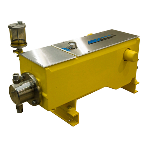
Accudyne Industries Milton Roy Milroyal Series User manual

Electronic Capacity
Control IOM Manual
MAXROY®B, MACROY®, mRoy®, and
Milroyal®Product Family Pumps
Manual No : 53870
Rev. : 00
Rev. Date : 10/2015


iInstallation, Operations & Maintenance Manual
PRECAUTIONS
The following precautions should be taken when working with metering pumps.
Please read this section carefully prior to installation.
Protective Clothing
ALWAYS wear protective clothing, face shield, safety glasses and gloves when working on or
near your metering pump. Additional precautions should be taken depending on the solution
being pumped. Refer to Safety Data Sheets for the solution being pumped.
Hearing Protection
It is recommended that hearing protection be used if the pump is in an environment where the
time weighted average sound level (TWA) of 85 decibels is exceeded (as measured on the A
scale slow response).
Electrical Safety
• Remove power and ensure that it remains off while maintaining pump.
• DO NOT FORGET TO CONNECT THE PUMP TO EARTH.
• Electric protection of the motor (Thermal protection or by means of fuses) is to correspond
to the rated current indicated on the motor data plate.
Liquid Compatibility
Verify if the materials of construction of the wetted components of your pump are
recommended for the solution (chemical) to be pumped.
Pumps Water “Primed”
All pumps are tested with water at the factory. If your process solution is not compatible with
water, ush the Pump Head Assembly with an appropriate solution before introducing the
process solution.
Plumbing and Electrical Connections
Always adhere to your local plumbing and electrical codes.
Line Depressurization
To reduce the risk of chemical contact during disassembly or maintenance, the suction and
discharge lines should be depressurized before servicing.
Over Pressure Protection
To ensure safe operation of the system it is recommended that some type of safety/pressure -
relief valve be installed to protect the piping and other system components from damage due
to over-pressure.
Lifting
This manual should be used as a guide only - Follow your company’s recommended lifting
procedures. It is not intended to replace or take precedence over recommendations, policies
and procedures judged as safe due to the local environment than what is contained herein.
Use lifting equipment that is rated for the weight of the equipment to be lifted.

ii Installation, Operations & Maintenance Manual
IMPORTANT SAFETY INSTRUCTIONS
WHEN INSTALLING, CALIBRATING, OR OPERATING THIS ACTUATOR, BASIC SAFETY PRECAUTIONS
SHOULD ALWAYS BE FOLLOWED TO REDUCE RISK OF FIRE, ELECTRIC SHOCK, AND PERSONAL
INJURY. FAILURE TO FOLLOW THESE INSTRUCTIONS COULD RESULT IN DEATH OR SERIOUS INJURY.
Read all instructions before installation, calibration, or operation.
GENERAL SAFETY CONSIDERATIONS
• Read this manual carefully.
• Installation, calibration, and maintenance should be performed by trained and qualied personnel.
Personnel should be familiar with the precautions required in working with hazardous voltages which
exist inside the actuator. Personnel should also be adequately trained on any hazards inherent in the
chemicals used in the metering pump.
• Always wear protective clothing including gloves and safety glasses when working on or near chemical
metering pumps.
• Follow directions and warnings provided with the chemicals from the chemical manufacturer. User is
responsible for determining the hazards associated with the chemicals being pumped and using the
proper safety gear and procedures.
• Hazardous voltages are present when cover is removed. Disconnect power when installing or servicing
this unit.
• Unit must be properly grounded.
• Conform to local codes in wiring this equipment.
• Actuator must be adequately rated if it is to be used in a hazardous location. See product data plate
for rating information. This rating must not be exceeded under any circumstances. To prevent ignition
of hazardous atmospheres, cover must be tight while circuits are energized.
• In order to comply with the requirements of agency approvals (see data plate), specications for
conduits connections, wire gauge and type, fastener torque ratings, and operating condition must be
adhered to.

iiiInstallation, Operations & Maintenance Manual
GENERAL SAFETY CONSIDERATIONS FOR IECEx RATED APPLICATIONS
• Actuator is to be cleaned regularly to prevent a buildup of dust on the enclosure.
DO NOT OPEN THE ACTUATOR WHEN AN EXPLOSIVE ATMOSPHERE IS PRESENT.
ACTUATOR MUST BE GROUNDED.
POTENTIAL ELECTROSTATIC CHARGING HAZARD – GROUNDING EQUIPMENT WILL NOT PREVENT
PROPAGATING BRUSH CHARGES. THE EQUIPMENT SHOULD NOT BE SUBJECTED TO CHARGING
MECHANISMS STRONGER THAN MANUAL RUBBING.
• Earthing (protective) conductor is to be ≥ the size of the phase conductors and equipotential bonding
conductors are to be minimum 4mm2(10 AWG) cross sectional area.
• The ground lug shall be tightened to the earthing connector so that contact pressure on the electrical
connections shall be maintained and not loosen due to temperature or humidity.
• Only suitable rated IECEx approved Ex d cable glands are to be employed that also maintain the IP6X
rating.
• Only suitable cable and cable glands or conductors in conduits rated to 100°C are to be employed to
maintain the temperature rating.
• Only suitable rated IECEx approved Ex d blanking elements are to be employed that also maintain
the IP6X rating.
• If required, only IECEx approved blanking elements are to be employed and shall not be used with
an adaptor.
• Only suitable rated IECEx approved Ex d thread adaptors are to be employed that also maintain the
IP6X rating.
• If required, only IECEx approved devices are to be employed.

iv Installation, Operations & Maintenance Manual
QUICK START GUIDE
NOTE:
Read and understand safety instruction before proceeding.
READ
• Read and comply with all safety instructions presented in this manual. In order to comply with the
requirements of agency approvals (see data plate), specications for conduit connections, wire gauge
and type, fastener torque ratings, and operating conditions must be adhered to.
CONNECT
• Connect AC power. Use conduit connections or cable glands.
• Ground unit.
• Connect command signal.
• Connect feedback signal.
VERIFY
• Voltage selector switch is set to the required voltage (115 or 230 VAC).
• DIP switches are set for desired operation.
• Command input signal is set to desired operation 4-20 mA or (-5 VDC). Factory set at 4-20 mA.
• Feedback signal output is set to desired operation 4-20mA or (1-5 VDC). Factory set at 4-20 mA.
• Loss of command signal action (unit moves to low signal position or hold last position). Factory setting
moves unit to low signal position.
• If reverse action is required (optional, visit factory website).
HAZARDOUS VOLTAGES ARE PRESENT ON THE CIRCUIT BOARD. TO PREVENT IGNITION OF
HAZARDOUS ATMOSPHERES, COVER MUST BE TIGHT WHILE CIRCUITS ARE ENERGIZED.
APPLY POWER
• Apply command signal.
• Apply AC power.
OBSERVE
• Actuator should run to command position and stop.
• Full range of command signal should result in desired range of actuator travel (factory setting is for
full travel of 0% to 100%).
CALIBRATE
• If actuator was installed on the pump at the factory, it has been factory calibrated.
• If actuator is retrot or a non-standard range is desired, follow the calibration instructions in this
manual.
FINISH
• Install cover. Observe torque requirements of 15 ft-lb (20 N-m) in hazardous location.
• If the unit is IECEX/ATEX certied, tighten the set screw in the base to lock the cover to maintain the
rating and prevent tampering.

vInstallation, Operations & Maintenance Manual
IMPORTANT SAFETY INSTRUCTIONS ........................................................ ii
QUICK START GUIDE ......................................................................iv
SECTION 1 - GENERAL DESCRIPTION ....................................................... 1
1.1 GENERAL INFORMATION ......................................................... 1
1.2 PRINCIPLE OF OPERATION ....................................................... 1
1.3 SPECIFICATIONS ................................................................ 2
1.4 PRODUCT MODEL CODING ....................................................... 2
1.5 AGENCY APPROVALS ............................................................ 5
SECTION 2 - INSTALLATION ................................................................ 7
2.1 GENERAL INFORMATION ......................................................... 7
2.1.1 Field Installation of ECC .......................................................... 7
2.1.2 ECC Circuit Board Replacement.................................................... 7
2.1.3 Circuit Board Replacement For ECC(s) Built After January 2000 and/or After A Circuit Board
Retrot Kit is Replaced ........................................................... 7
2.2 UNPACKING .................................................................... 8
2.3 STORAGE/IDLE SERVICE ......................................................... 8
2.4 SAFETY PRECAUTIONS .......................................................... 8
2.5 MOUNTING ..................................................................... 8
2.6 WORKING WITH THE COVER ...................................................... 9
2.7 ELECTRICAL CONNECTIONS ...................................................... 9
2.7.1 Installation of Input/Output Command Signal Wiring..................................... 9
2.7.2 Input Signal ................................................................... 10
2.7.3 Feedback Output Signal ......................................................... 10
2.7.3.1 Feedback Output Signal 4-20 mA ................................................ 10
2.7.3.2 Feedback Output Signal 1-5 VDC................................................. 10
2.7.4 Installation of Primary Power Wiring ................................................ 11
2.8 CIRCUIT BOARD RETROFIT KIT INSTALLATION ...................................... 11
2.8.1 Remove Old Circuit Board ....................................................... 11
2.8.2 Required Modications .......................................................... 11
2.8.2.1 ECC Part Number 0152226XXX, 0152195XXX ...................................... 12
2.8.3 Install New Circuit Board ........................................................ 12
SECTION 3 - OPERATION ................................................................. 14
3.1 CONTROLS.................................................................... 14
3.2 INITIAL START-UP............................................................... 14
3.2.1 Operating Modes .............................................................. 14
3.2.2 Input Signal................................................................... 15
3.3 CONTROL RANGE ADJUSTMENT ................................................. 16
TABLE OF CONTENTS

vi Installation, Operations & Maintenance Manual
SECTION 4 – MAINTENANCE .............................................................. 18
4.1 SPARE PARTS ................................................................. 18
4.2 RETURNING UNITS TO THE FACTORY ............................................. 18
4.3 MAINTENANCE ................................................................ 18
4.4 PRINTED CIRCUIT BOARD (PCB) REPLACEMENT.................................... 19
4.4.1 Removal of PCB ............................................................... 19
4.4.2 Installation of PCB ............................................................. 19
4.5 FEEDBACK POTENTIOMETER REPLACEMENT ...................................... 19
4.5.1 Removal of Feedback Potentiometer ............................................... 19
4.5.2 Installation of Feedback Potentiometer.............................................. 20
4.6 NYLON WORM GEAR REPLACEMENT.............................................. 20
4.6.1 Removal of Nylon Worm Gear .................................................... 20
4.6.2 Installation of Nylon Worm Gear................................................... 20
4.7 MOTOR REPLACEMENT ......................................................... 20
4.7.1 Removal of Motor .............................................................. 20
4.7.2 Installation of Motor ............................................................. 21
4.8 ECC CALIBRATION.............................................................. 22
4.8.1 Calibration Routines ............................................................ 22
4.8.1.1 Calibration A................................................................. 22
4.8.1.2 Calibration B................................................................. 24
4.8.1.3 Calibration C ................................................................ 25
SECTION 5 - TROUBLESHOOTING .......................................................... 28
SECTION 6 - PARTS LIST .................................................................. 29
6.1 GENERAL ..................................................................... 29
6.2 ILLUSTRATED PARTS LIST ....................................................... 29
6.3 ELECTRONIC CAPACITY CONTROL PARTS LIST ..................................... 33
6.4 PARTS LIST FOR mROY®ECC MOUNTING ADAPTER (mROY®“A” ) ....................... 37
6.5 PARTS LIST FOR mROY®ECC MOUNTING ADAPTER (mROY®“B”) ....................... 39
6.6 PARTS LIST FOR MACROY®ECC MOUNTING ADAPTER (MACROY®“G”, “D” AND
MILROYAL®G).................................................................. 42
6.7 PARTS LIST FOR MAXROY®ECC MOUNTING ADAPTER (MAXROY®“B”) .................. 45
6.8 PARTS LIST FOR MILROYAL®ECC MOUNTING ADAPTER AND MOUNTING ADAPTER
GUARD ASSEMBLY (MILROYAL®“B”) ............................................... 48
6.9 PARTS LIST FOR MILROYAL®ECC MOUNTING ADAPTER AND GEAR DRIVE
(MILROYAL®“C”) ................................................................ 50
6.10 PARTS LIST FOR MILROYAL®ECC MOUNTING (MILROYAL®D) ......................... 52
APPENDIX A MAXROY®B PUMP ECC INSTALLATION (RETROFIT) .......................... 53
APPENDIX B MILROYAL®B PUMP FIELD INSTALLATION (RETROFIT) ....................... 54
APPENDIX C MILROYAL®C PUMP FIELD INSTALLATION (RETROFIT) ....................... 56

viiInstallation, Operations & Maintenance Manual
LIST OF ILLUSTRATIONS
FIGURE 1. Nema 4 Electronic Capacity Control Data Plate......................................... 5
FIGURE 2. Nema 7 Electronic Capacity Control Data Plate......................................... 5
FIGURE 3. IECEX/ATEX Certied Electronic Capacity Control Data Plate ............................. 5
FIGURE 4. Declaration of Conformity.......................................................... 6
FIGURE 5. Circuit Board Connectors J4 and J5................................................. 10
FIGURE 6. Circuit Board, 30033 ............................................................ 13
FIGURE 7. Circuit Board, 0152226XXX, 0152195XXX ............................................ 13
FIGURE 8. Conversion Detail ............................................................... 13
FIGURE 9. Jumper Plugs/Action Mode Conversion .............................................. 14
FIGURE 10. Effect of Zero & Span Controls..................................................... 15
FIGURE 11. Split Range Operation with Two Pumps (Typical pH Control System) ....................... 15
FIGURE 12. Circuit Board, Top............................................................... 17
FIGURE 13. Circuit Board, Bottom ............................................................ 17
FIGURE 14. Circuit Board Removed .......................................................... 19
FIGURE 15. Potentiometer Connector P2 Pins 1 and 2 ............................................ 23
FIGURE 16A. Electronic Capacity Control (DWG 1022483000)...................................... 30
FIGURE 16B. Electronic Capacity Control with Setscrew........................................... 31
FIGURE 16C. Electronic Capacity Control (DWG 1022483000)...................................... 32
FIGURE 17. mRoy®“A” ECC Mounting Adapter (DWG. 1021971000) .................................. 36
FIGURE 18. mRoy®“B” ECC Mounting Adapter (DWG. 10221460003) ................................ 38
FIGURE 19A. MACROY®“G” ECC Mounting Adapter (DWG. 1022118000) Design through
“September 2004” and Milroyal®“G”. ............................................... 40
FIGURE 19B. MACROY®“D” ECC Mounting (DWG. 1021572000) ................................... 41
FIGURE 20. MAXROY®B ECC Mounting Adapter (DWG. 1021572000) ............................... 44
FIGURE 21A. Milroyal®B ECC Mounting Adapter (DWG 1022095000) ................................ 46
FIGURE 21B. Milroyal®B ECC Mounting Adapter Guard Assy (DWG 1022095000) ...................... 47
FIGURE 22. Milroyal®C ECC Mounting Adapter (DWG. 10222850002)................................ 49
FIGURE 23. Milroyal®D ECC Mounting Adapter (DWG. 1022906000)................................. 51

viii Installation, Operations & Maintenance Manual
THIS PAGE INTENTIONALLY LEFT BLANK

1
Installation, Operations & Maintenance Manual
SECTION 1 - GENERAL DESCRIPTION
1.1 GENERAL INFORMATION
In this age of sophisticated process control
concepts, many people are taking advantage of
the latest breakthroughs in technology to upgrade
their own equipment and systems. The Milton
Roy Electronic Capacity Control (ECC) easily
interfaces with computerized process and process
instruments, as the ECC will adjust the output of a
metering pump from 0% to 100% in response to a
4 to 20 mA or 1 to 5 VDC signal from a computer
or other source. This outstanding feature can be
purchased as an integral part of the pump, or it can
be bought separately and eld installed. The ECC
mounts to the housing of the pump and operates
in place of the manual stroke adjustment.
1.2 PRINCIPLE OF OPERATION
The ECC allows remote adjustment of the
volume of liquid delivered by the metering
pump. This is accomplished by utilizing a
4-20 mA command signal from a Milton Roy
Remote Panel Mount (ARPM-100/200) or Remote
Wall Mount (ARWM-100/200) remote controller
(Manual No 53944), or a customer’s control
system. In a closed loop control system, the ECC
accepts the computer or controller 4-20 mA signal
directly and provides immediate and accurate
control of the pump ow under varying process
conditions.
SECTION 1 - GENERAL DESCRIPTION
When the ECC receives the 4-20 mA command
signal, the drive motor responds by moving the
ECC to the required position. As the ECC moves,
it changes the position of the pump’s stroke adjust
shaft, thus altering the pump’s ow rate. Refer to
Table 1 which lists reference manuals containing
information on the stroke adjust shaft and pump
operation.
Table 1. Stroke Adjust Shaft & Pump
Operation Reference Manuals
NOTE:
As supplied, the ECC is direct acting (pump
capacity increases with increasing input signal
to ECC) although it may be converted to reverse
acting by following the procedure outlined in
Section 3, “Operation”.
Pump Manual
mRoy®53829
MAXROY®B 53938
Milroyal®C 53939
Milroyal®B 53940
Milroyal®D 53941
MACROY®G 53873
MACROY®D 53872
Milroyal®G 53942

2Installation, Operations & Maintenance Manual
1.3 SPECIFICATIONS 1.4 PRODUCT MODEL CODING
MAXROY®B, mRoy®, MACROY®and Milroyal®
product family pumps can be ordered with or
without an ECC already attached. If the ECC is
ordered with the pump, it is indicated in the pump
model code by an “E1”, “E2”, “EA” or “EB” in the
capacity adjustment slot. The pump model code
can be found on the pump data plate, mounted to
the pump.
There are four ECC’s customarily supplied with
a pump; these models are shown in the product
model code tables (Table 2 - Table 8). There are
several very similar ECC data plates and some of
these are shown in Figure 1 and Figure 2. Please
note that the Figure 2 data plate documents what
safety and/or hazardous location approvals apply
to the unit.
Model
Number Enclosure Voltage
50/60 Hz
PPRW212RMH Nema 4X 115 VAC
PPRW512RMH Nema 4X 230 VAC
PPRX212RMH
Explosion Proof
and Nema 4X
(FM Approved)
115 VAC
PPRX512RMH
Explosion Proof
and Nema 4X
(FM Approved)
230 VAC
PPRX212RMH-I
Explosion Proof
and Nema 4X
IECEX/ATEX
IP66
115 VAC
PPRX512RMH-I
Explosion Proof
and Nema 4X
IECEX/ATEX
IP66
230 VAC
Table 2. mRoy®Model Codes
SECTION 1 - GENERAL DESCRIPTION
Input Power
115 VAC, 50/60Hz, 1 phase
±10% (standard)
230 VAC, 50/60Hz, 1 phase
±10% (optional) 1 amp max
Control Signal
Input
4-20 mA into 250 ohms
impedance (standard)
Direct acting : 4-20 mA
(see note below)
Split range : 4-12 mA,
12-20 mA
Position Feedback
Output
4-20 mA, max 500 ohm load
(standard)
1-5 VDC, min 250 ohms imped-
ance, DIP selectable (optional)
Motor RPM 72
Accuracy ±0.5%
Manual Operation Fluted handwheel with ECC
unpowered
Enclosure
NEMA 4X, IP66 (standard)
Hazardous location (optional)
Enclosure is aluminium with
Stainless Steel (SS) shaft
Travel Time (0%to
100%)
mRoy®10 seconds
MAXROY®B 3 minutes
Milroyal®D 1 minute
MACROY®D
and G 3 minutes
Milroyal®B, C
and G 3 minutes
Duty Cycle
100% Continuous up to 110°F
75% at 120°F
50% at 140°F
Environmental
-40°F to 140°F (-40°C to 60°C)
Altitude max 6559ft (2000m)
Relative humidity max 80%
up to 87°F (31°C), decreasing
linearly to 50% at 104°F
(40°C) Installation category 2
(EN61010-1), Pollution degree
2 (EN61010-1)

3
Installation, Operations & Maintenance Manual
SECTION 1 - GENERAL DESCRIPTION
Model
Number Enclosure Voltage
50/60 Hz
PPGW222RMH Nema 4X 115 VAC
PPGW522RMH Nema 4X 230 VAC
PPGX222RMH-I
Explosion Proof
and Nema 4X
IECEX/ATEX
IP66
115 VAC
PPGX522RMH-I
Explosion Proof
and Nema 4X
IECEX/ATEX
IP66
230 VAC
Table 3. MAXROY®B Model Codes
Model
Number Enclosure Voltage
50/60 Hz
PPGW242LMH Nema 4X 115 VAC
PPGW542LMH Nema 4X 230 VAC
PPGX242LMH-I
Explosion Proof
and Nema 4X
IECEX/ATEX
IP66
115 VAC
PPGX542LMH-I
Explosion Proof
and Nema 4X
IECEX/ATEX
IP66
230 VAC
Table 4. Milroyal®B Model Codes
Model
Number Enclosure Voltage
50/60 Hz
PPGW482LMH Nema 4X 115 VAC
50/60 Hz
PPGW682LMH Nema 4X 230 VAC
60 Hz
PPGW782LMH Nema 4X 230 VAC
50 Hz
PPGX482LMH-I
Explosion Proof
and Nema 4X
IECEX/ATEX
IP66
115 VAC
50/60 Hz
PPGX682LMH-I
Explosion Proof
and Nema 4X
IECEX/ATEX
IP66
230 VAC
60 Hz
PPGX782LMH-I
Explosion Proof
and Nema 4X
IECEX/ATEX
IP66
230 VAC
50 Hz
Table 5. Milroyal®C Model Codes

4Installation, Operations & Maintenance Manual
SECTION 1 - GENERAL DESCRIPTION
Model
Number Enclosure Voltage
50/60 Hz
Low Pressure
PPGW292LMH Nema 4X 115 VAC
Low Pressure
PPGW592LMH Nema 4X 230 VAC
Low Pressure
PPGX292LMH-I
Explosion Proof
and Nema 4X
IECEX/ATEX
IP66
115 VAC
Low Pressure
PPGX592LMH-I
Explosion Proof
and Nema 4X
IECEX/ATEX
IP66
230 VAC
High Pressure
PPGW212LMH Nema 4X 115 VAC
High Pressure
PPGW512LMH Nema 4X 230 VAC
High Pressure
PPGX212LMH-I
Explosion Proof
and Nema 4X
IECEX/ATEX
IP66
115 VAC
High Pressure
PPGX512LMH-I
Explosion Proof
and Nema 4X
IECEX/ATEX
IP66
230 VAC
Table 6. Milroyal®D Model Codes
Model
Number Enclosure Voltage
50/60 Hz
PPGW242LMH Nema 4X 115 VAC
PPGW542LMH Nema 4X 230 VAC
PPGX242LMH-I
Explosion Proof
and Nema 4X
IECEX/ATEX
IP66
115 VAC
PPGX542LMH-I
Explosion Proof
and Nema 4X
IECEX/ATEX
IP66
230 VAC
Table 7. Milroyal®G Model Codes
Model
Number Enclosure Voltage
50/60 Hz
PPGW242LMH Nema 4 115 VAC
PPGW542LMH Nema 4 230 VAC
PPGX242LMH-I
Explosion Proof
and Nema 4X
IECEX/ATEX
IP66
115 VAC
PPGX542LMH-I
Explosion Proof
and Nema 4X
IECEX/ATEX
IP66
230 VAC
Table 8. MACROY®D and G Model Codes

5
Installation, Operations & Maintenance Manual
1.5 AGENCY APPROVALS
(Figures 1, 2 and 3)
THE DATA PLATE DOCUMENTS
ALL SAFETY AND/OR HAZARD-
OUS LOCATION APPROVALS THAT APPLY THESE ARE NOT TO
BE EXCEEDED.
The data plate documents all safety and/or
hazardous location approvals that apply to the unit.
See Figures 1 and 2 for data plate congurations.
All of or some of the following approvals may apply:
.
Figure 1. Nema 4X Electronic Capacity Control Data Plate.
SECTION 1 - GENERAL DESCRIPTION
A declaration of conformity (Figure 3) lists the
standards declared by the Milton Roy.
MET Labs U.S. Safety and Explosion
proof
MET Labs Canadian Safety and
Explosion proof
CSA CSA 25/30
CE
Safety
EN61010-1 Installation
category 2
Pollution degree 2
EMC directives Emissions EN50081-2
Immunity EN50082-2
CENELEC (Flameproof) EN 50014 &
50018
FM Factory Mutual explosion
proof
ATEX
EN60079-0
EN60079-1
EN60079-31
IECEX
IEC 60079-0
IEC 60079-1
IEC 60079-31
Figure 2. Nema 7 Electronic Capacity Control Data Plate. (Discontinued)
Figure 3. IECEX/ATEX Certied Electronic Capacity Control Data Plate.

6Installation, Operations & Maintenance Manual
Figure 4. Declaration of Conformity

7
Installation, Operations & Maintenance Manual
SECTION 2 - INSTALLATION
2.1 GENERAL INFORMATION
The ECC is usually shipped already mounted to
the pump. Installation, therefore, is usually only a
matter of connecting the signal wiring (paragraph
2.6.1) and primary power wires (paragraph 2.6.4).
Model numbers containing (-I) are IECEX/ATEX
approved. Actuators containing (-I) model code
will come with the locking set screw in the base
(see gure 15B). Unlock the set screw for cover
removal. Tighten the set screw to lock the cover
to maintain rating and prevent tampering. Hex key
for set screw adjustment is shipped with actuator.
2.1.1 Field Installation of ECC
Field installation of the ECC to an existing pump
is usually not recommended due to the precise
alignment required.
MACROY®G and MACROY®D pumps cannot be
converted in the eld to ECC operation.
mRoy®A/B pumps manufactured before 1987
cannot be converted in the eld to ECC operation.
The mRoy®A/B pump housing must have
been machined to mount an ECC. Contact the
Milton Roy service department if you wish to convert
a manually adjusted mRoy®pump manufactured
after 1987 to ECC operation.
If the ECC was supplied as a field mounting
kit, refer to eld installation instructions for the
following pumps; MAXROY®B (Appendix A),
Milroyal® B (Appendix B) or Milroyal®C (Appendix C).
Upon completion of the retrofit, proceed with
service connections (paragraph 2.4).
2.1.2 ECC Circuit Board Replacement
As ECC circuit boards fail (ECC(s) built before
January 2000) at field installations, they are
replaced with an ECC circuit board retrofit kit
(see Table 9). The circuit board retrot kit replaces
the old circuit board with a new unit. Match your
Milton Roy pump to the correct circuit board retrot
kit part number using Table 9. Refer to Circuit Board
retrot kit installation (paragraph 2.7).
2.1.3 Circuit Board Replacement For ECC(s)
Built After January 2000 and/or After A
Circuit Board Retrot Kit Is Replaced.
After a conversion kit is installed in the eld and/or
a new ECC circuit board (ECC(s) built after January
2000) fails order replacement board p/n 30300 for
all pumps except Milroyal®C. Order p/n 39320 for
Milroyal®C pumps.
NOTE:
When ordering the replacement board
(p/n 30300/39320) specify what pump the unit
is being installed on to insure the replacement
board is congured for your pump.
This will eliminate problems during installation.
Refer to Printed Circuit Board Replacement
(paragraph 4.4, Section 4).
Part
Number
For ECC(s) Built Before
January 2000
21226 mRoy® A & B with 115 VAC 50/60 Hz
input power
21227 mRoy® A & B with 230 VAC 50/60 Hz
input power
21228
Milroyal®B, Milroyal®G or
MACROY® G with 115 VAC 50/60 Hz
input power
21229
Milroyal®B, Milroyal®G or
MACROY® G with 230 VAC 50/60 Hz
input power
21230 Milroyal® C with 115 VAC 50/60 Hz
input power
21231 Milroyal® C with 60 Hz 230 VAC
input power
21232 Milroyal® C with 50 Hz 230 VAC
input power
21233 Milroyal®D or MACROY®D
with 115 VAC 50/60 Hz input power
21234 Milroyal®D or MACROY®D
with 230 VAC 50/60 Hz input power
21235 MAXROY® B with 115 VAC 50/60 Hz
input power
21236 MAXROY® B with 230 VAC 50/60 Hz
input power
Table 9. ECC Circuit Board Retrot Kits

8Installation, Operations & Maintenance Manual
SECTION 2 - INSTALLATION
2.2 UNPACKING
Units are shipped Free on Board (FOB) factory
and the title passes to the customer when the
carrier signs for receipt of the unit. In the event
that damages occur during shipment, it is the
responsibility of the customer to notify the carrier
immediately and to le a damage claim.
Carefully examine the shipping crate/box upon
receipt from carrier to be sure there is no obvious
damage to contents. Open the crate/box carefully
so accessory items fastened to the inside of the
crate/box will not be damaged or lost. Examine
all material inside crate/box and check against
packing list to be sure that all items are accounted
for and intact.
2.3 STORAGE/IDLE SERVICE
Several ECC components are steel and are subject
to corrosive attack during storage/idle time in hot,
humid environments. The ECC covers are not air
tight. In humid environments, the humidity in the
air can condense during cooler evenings, even
to the extent that water can accumulate inside
the housing. Milton Roy does not warrant against
damage caused by corrosion or atmospheric
conditions.
With reasonable care at the site, the products and
packaging methods will effectively protect new,
uninstalled units from corrosion due to water and
water vapor for up to one year.
FAILURE TO PROPERLY STORE
AND PROTECT THE EQUIPMENT
MAY VOID ANY WARRANTY, EXPRESSED OR IMPLIED.
OUTDOOR STORAGE IS NOT RECOMMENDED UNDER ANY
CIRCUMSTANCES UNLESS SPECIFICALLY PREPARED FOR
STORAGE PRIOR TO SHIPMENT FROM THE FACTORY.
The amount of time the ECC can remain in storage
or idle service can be extended. Depleted, factory
installed desiccant can be removed and replaced
with new desiccant. Visit the factory website
(www.miltonroy.com) for instructions to properly
extend ECC storage.
Maximum Estimated Storage
2.4 SAFETY PRECAUTIONS
When installing, operating, and maintaining
the ECC, keep safety considerations foremost.
Use proper tools, protective clothing and eye
protection when working on the equipment and
install the equipment with a view toward ensuring
safe operation. Follow the instructions in this
manual and take additional safety measures
appropriate to the liquid being pumped. Be
extremely careful in the presence of hazardous
substances (e.g. corrosives, toxics, solvents, acids,
caustics and ammables etc.)
2.5 MOUNTING
The Milton Roy ECC is commonly shipped already
mounted on a pump. Because of this, installation
usually requires connecting the power and signal
wires. If the ECC was shipped without a pump,
mounting to your pump and minor calibration
adjustment is required (Full calibration is performed
at the factory and only limited calibration is required
after mounting). ECCs installed on pumps outdoors
should be protected by a shelter. Care should be
taken to keep condensation and moisture from
entering via the electrical conduit.
Indoors, dry ambient controlled temperature
Initial 12 months
Extend preservation 12 additional months
Indoors, dry ambient uncontrolled temperature
Initial 6 months
Extend preservation 6 additional months
Outdoor storage Not recommended

9
Installation, Operations & Maintenance Manual
SECTION 2 - INSTALLATION
2.6 WORKING WITH THE COVER
Explosion proof units have a set screw in the
base to lock the cover after it’s installed. This is
to maintain the explosion proof rating and prevent
tampering. On explosion proof units, to remove
the cover, rst loosen the set screw in the base
using a 5/64” hex key. Then unscrew the cover.
To install the cover, screw it on all the way. The
cover can be torqued to 15 lb.ft (20 N.m). Then
snug the locking set screw in the base using a 5/64”
hex key to prevent the cover from being unscrewed.
2.7 ELECTRICAL CONNECTIONS
The electrical connections for the ECC are input
signal, feedback output signal, and input power.
Terminal blocks, with removable connectors are
located on the bottom of the circuit board under
the ECC cover. Conduit access to the ECC is via
two threaded 1/2-14 inch NPT threaded openings
in the ECC base.
The Milton Roy ECC is commonly shipped with
red ½ - 14 inch NPT plastic plugs in the conduit
access openings. During installation, remove
these shipping plugs and do not use them. Use
appropriate cable glands instead. For IECEx
installations, use an explosion proof conduit seal
applied by the installer or user of the equipment
according to code.
All wiring should conform to National Electrical
codes or local codes as they apply. Conduit
bushings must be chosen to provide NEMA 4,
and explosion proof integrity. In North America,
use NEMA type 4 and/or explosion proof conduit
ttings. In Europe, cable glands with IP66 and/or
Ex d ratings are readily available with 1/2-14 inch
NPT threads.
ALWAYS DISCONNECT PRIMARY
POWER BEFORE REMOVING
THE COVER FROM THE ECC. FAILURE TO FOLLOW THESE
INSTRUCTIONS COULD RESULT IN DEATH OR SERIOUS
INJURY.
AVOID DAMAGE TO SENSITIVE
ELECTRONICS, REMOVE THE
COVER FROM THE ECC CAREFULLY
2.7.1 Installation of Input/Output Command
Signal Wiring
1. To remove the cover: explosion proof units have
a set screw in the base that locks the cover when
it is closed and maintains its explosion proof
rating. To remove the cover, rst loosen the set
screw in the base using a 5/64” hex key.
2. Unscrew the ECC cover by turning it
counterclockwise (as viewed from the top).
Lift the cover straight off and away.
IMPROPER CONNECTION OF
THE COMMAND LINES CAN
CAUSE DAMAGE TO THE ECC. USE ONLY 300 VOLT, 105°C
RATED WIRE, MINIMUM 22 AWG, MAXUMUM 14 AWG.
3. Maintain integrity of safety approvals using
only 300 volt, 105° C (UL 1213 or equiv.) rated
insulation. Maintain CE immunity ratings, using
shielded cable inside of conduit.
4. Feed four (14 to 22 AWG) shielded wires
through appropriately rated conduit bushing
inserted into one of the conduit holes in base
of ECC. Ground shields for four wires to a good
chassis ground at control end.
5. Route wires to ECC keeping electrical
interference to a minimum. Carefully pull
four-position connector J5 from circuit board.
Connect command signal wires to connector
J5 (Figure 4 and 12). Reconnect connector J5
to circuit board.

10 Installation, Operations & Maintenance Manual
SECTION 2 - INSTALLATION
2.7.2 Input Signal
The input signal, used to control the ECC, can
be either 4-20 mA or 1-5 VDC. A ve-position Dip
switch, SW2 (Figure 11, located on the top of the
circuit board) selects the control signal used by
the operator. The factory sets SW2 for the model
ordered and should not need changed. Position 1
(Table 10) of SW2 sets the input signal. Position 2
sets the movement of the ECC after unintentional
loss of the control signal. Position 3 and 4 sets
the ECC for use with a pump or valve and should
always be set to 3-OFF and 4-ON for the pump
mode. Position 5 is not used.
2.7.3 Feedback Output Signal
A position output, proportional to ECC position,
is used for remote position indication. A current
of 4-20 mA or a voltage of 1-5 VDC is available
between MONITOR (J5-4) and COMMON (J5-3).
Feedback zero and feedback span adjustments
(Figure 11) are provided to ne tune the output
(see calibration instructions). DIP switch SW3
(Figure 11) selects the feedback output signal. Use
of the output signal is optional.
2.7.3.1 Feedback Output Signal 4-20 mA
NOTE
Do not connect the 4-20 mA output to a circuit
with greater than a 500 ohm load.
Set SW3 per Table 11 for a 4-20 mA feedback
signal.
2.7.3.2 Feedback Output Signal 1-5 VDC
NOTE
Do not connect the 1-5 VDC output to a circuit
having less than 250 ohms impedance.
Set SE3 per Table 11 for a 1-5 VDC feedback
signal.
Figure 5. Circuit Board Connectors J4 and J5
INPUT SWITCH POSITION
1 2 3 4 5
Input Signal of
4-20 mA ON
Input Signal of
1-5 VDC OFF
Hold Position on
Loss of Control
Signal
ON
Return to Lower
Limit on Loss of
Control Signal
OFF
Pump Mode
(limits absolute) OFF ON
Valve Mode
(limits oating) ON OFF
Not Used NC
Table 10. SW2 DIP Switch Settings
Table 11. SW3 DIP Switch Settings
OUTPUT SWITCH POSITION
1 2 3 4 5
Output Signal of
4-20 mA ON ON OFF OFF OFF
Output Signal of
1-5 VDC OFF OFF ON ON ON
This manual suits for next models
43
Table of contents
Other Accudyne Industries Water Pump manuals
Popular Water Pump manuals by other brands

Wilo
Wilo Drain TP 80 Installation and operating instructions

Idex
Idex WARREN RUPP SandPIPER PB1-A Service and operating manual

Wilo
Wilo Wilo-CronoLine-IL Installation and operating instructions

baxter
baxter Flo-Gard 6301 Service manual

Grundfos
Grundfos CMB Supplement to Quick Guide

Kegco
Kegco Deluxe instruction manual