Acer AT4202P User manual

1
Trident EX52 compatibly model:
AT4202P
ACER SERVICE MANUAL

2
THIS DOCUMENT IS FOR REPAIRSERVICE INFORMATION ONLY.
DATE:2006/02/13

Page 3 of 99
CONTENTS
1、SPECIFICATION..................................... ................ .................................... ..........…………...…..
4
1-1 General Sepecificaation..........................…….. ….......……....................... .....………....……. 5
1-2 Feature Summary....................................... .. ........ .............................……………...………….. 6
1-3 External Interface........................................... .. .........................................…………….....…… 7
1-3-1 Video/Audio Inputs……........................... .. ................. .. .. ...................... .............….. 8
1-3-1-1 TV Antenna Interface............. .. ................. .......... .. ................ .. .. ..............……… 8
1-3-1-2 Component Intputs........................................ ....... ....... . ...... ..................…………… 8
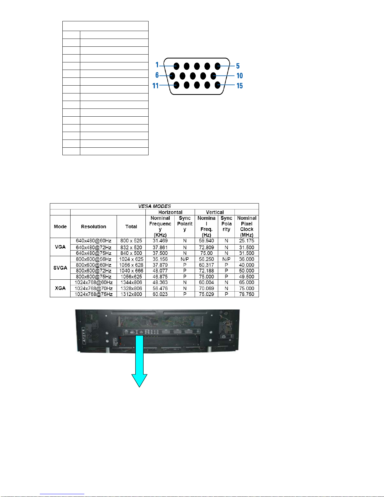
1-3-1-3 PC Input……………………………………………………………………………………… 8
1-3-1-4 DVI input……………………………………………………………………………………… 10
1-3-1-5 SCART Input……………………………………………………………………………… 11
1-3-2 Audio/Video Outputs………………………………………………………………………….. 12
1-3-2-1 Composite Video Output ……………………………………………………………….. 12
1-3-2-2 Analog Audio Output……………………………………………………………………… 12
1-3-2-3 Head Phone………………………………………………………………………………… 12
1-3-3Power Interface………………………………………………………………………………….. 12
1-3-3-1 Power Connector………………………………………………………………………….. 12
1-3-3-2 Power Input Range………………………………………………………………………… 13
1-3-3-3 Power Consumption……………………………………………………………………… 13
1-3-4 Service Interface……………………………………………………………………………….. 13
1-4 User interface………………………………………………………………………………………….. 14
1-4-1 Power Indicator……………………………………………………………………………….. 14
1-4-2 Remote Control Receiver…………………………………………………………………….. 14
1-5 External Mounting Requirements………………………………………………………………….. 14
1-6 Environmental Requirements ………………………………………………………………………. 14
1-6-1 Temperature Ranges………………………………………………………………………….. 14
1-6-2 Humidity…………………………………………………………………………………………. 14
1-6-3 Altitude………………………………………………………………………………………….. 14
1-6-4 Vibration and Shock………………………………………………………………………….. 14
2、Precautions and Notices......................... ..............................................................……………...… 14
2-1 Precaution of assembly……………..…... ............... ...... . ........... ............................................. 14
2-2 Precaution of Operation…………..…... ....... ................. ............ ..............................…………. 14
3、Operation.............................................. .... .....……………...............……………...…………………. 16
3-1 Operation of Remote Control Transmitter…….... ..... .......................................………………. 16
3-2 Key function..................................................... ............. ..............................…………..…….. 17
3-3 OSD Main Explanation................................................................................................…….. 17
3-3-1 Main Menu ..................................................................................................................... 17
3-3-2 Search Menu………………………………………………................. ....................... 18
3-3-3 Video Menu.............................. ................................... . ............................................... 20
3-3-4 Audio Menu................................. ................................... . .............................................. 20
3-3-5 Time Menu................................. ................................... . .............................................. 21
3-3-6 Setting Menu................................ ................................... ............................................. 21
3-3-7 Screen Menu………………………………………………………………………………….. 22
3-3-8 Pip Menu………………………………………………………………………………………. 23
3-8-1-1 PIP Input Mode……………………………………………………………………….. 24
3-8-1-2 PIP Function Table List……………………………………………………………….. 24

Page 4 of 99
4、Trouble shooting chart.......................................... .................................. ....................…………..... 24
4-1 PANEL Trouble shooting…….………...................................... .....................................……… 24
4-2 Solution process of MGPC0……………………................ ...... ....... ........... ...... ................ ...... 25
4-2-1 Panel cannot be lit up………………............................... ....................................………. 25
4-2-1-1 Check peripheral circuits procedure....................... ....................................………. 25
4-2-1-2 Check Image board procedure…............................. ....................................……… 26
4-2-2 Picture Display --Dynamic picture abnormal………………………………………………. 27
4-2-3 DVI picture abnormal…………...................................... ........................... .......……….. 28
4-2-4 Component picture abnormal…...................................... .............. .......................……. 29
4-2-5 RGB Picture Abnormal……………………….............................. ................... .......... ….. 30
4-2-6 Video Picture Abnormal………………………………………………………………………. 31
4-2-7 DC Power Supply…………………………………………………………………………….. 32
4-3 TUNER&AUDIO BOARD FAULTS HANDLING…………………………………………………… 33
4-3-1 Check DC Power Supply…………………………………………………………………………… 33
4-3-2 Tuner Faults Handling…….………………………………………………………………………. 33
4-3-3 Tuner&Audio Board Faults Handling……..……………………………………………………… 34
5、White-Balance Adjustment………………………………………………………………………………… 35
5-1 Equipments list………..…………………………………. ………………………………………….. 35
5-2 Preparation and Adjustment process………. ……………………………………………………. 35
6、DDC program and test……………………………………...……………………………………….………. 37
6-1 Equipments list and prepare……………………...………………………………………………… 37
6-2 Program and test process………...………..………………………………………………………… 37
7、Flash Update………………………………………...……………………………………………………… 38
7-1 The list of Instrument………………………………………………………………………………….. 38
7-2 The operation explaining Flash Update…………………………………………………………….. 38
8、Software Administer Block diagram……………………………………………………………………… 41
8-1 Main Block diagram (Kernel part)………………………………………………………………… 41
8-2 SOURCE key Block diagram…………………………………………………………………………... 42
8-3 MENU key Block diagram…………………………………………………………………………….. 43
8-4 Mode Check Block diagram…………………………………………………………………………. 45
8-5 SCART Key Choose Process………………………………………………………………………… 45
9、Block diagram & Explain.......................………………………..............……………………………. 49
9-1 PDP block diagram and functions…………………….. ………….. ……………………………… 49
9-2 Image board block diagram and signal introduce……………………………………..…………… 50
9-2-1 Image board block diagram………………………………………………………………………… 50
9-2-2 Input signal introduce………………………………………………………………………………… 51
9-3 TUNER board block diagram…………………………………………………………………………. 51
10、Waveform of signal………………………………..….. ………..…….. …. ……………………..………. 52
10-1 Waveform of input signal……………..….. ………..…….. …. ……………………..……………. 52
10-2 Signal waveform in the image board. ………..…….. …. ……………………..………………… 55
11、11Check and Measure…………..….. …………..…….. …. ……………………..…………………….. 64
11-1 Image board………………..….. ……….. …. ……………..…….. …. ……………………..……. 64
11-1-1 Power Check and Measure….……..….. ………..…….. …. ……………………..……… 65

Page 5 of 99
11-1-2 Voltage value of IC necessary…………………………………………………………… 66
11-2 AUDIO and TUNER Board CHECK……………………………………………………………….. 66
12、Mechanical Introduction………………………………………………………………………………… 67
12-1 PDP Internal view……………………………………………………………………………………. 67
12-2 Mechanical of cabinet front disassembly…………………………………………………………. 68
12-3 Disassembly and assembly……………………………………………………………………….. 69
12-3-1 PDP stand removal………………………………………………………………………… 69
12-3-2 Back Cover Removal………………………………………………………………………. 70
12-3-3 Rear Low Cover removal…………………………………………………………………… 71
12-3-4 Main Board(MGPC) and TUNER AUDIO Board (TUPC)removal……………………… 72
12-3-5 PCB Plate Removal……………………………………………………………………….. 73
12-3-6 Key Board Remove……………………………………………………………………….. 74
12-3-7 Side AV Board Removal……………………………………………………………………. 75
12-3-8 Panel Module Removal…………………………………………………………………….. 76
12-4 Panel Wiring diagram……………………………………………………………………………… 77
13、PCB LAYOUT ……………………………………………………………………………………………… 79
13-1 Image broad PCB LAYOUT……………………………………………………………………… 79
13-2 TUNER board and AUDIO board PCB LAYOUT……………………………………………….. 80
14、Schematic diagram…………………………………………………………………………………………. 83

Page 6 of 99
1、SPECIFICATION
1-1-1 General Specificaation
Item Specification
Screen size 42 inch plasma display panel
Aspect 16:9
Display pixels 852 x 480 (WXGA)
Effective display size 933mm x 533mm
Number of color 16.7 million colors
Contrast Ration 10000:1 (in dark room)
Panel
Spec
Peak brightness 1500 cd/㎡
TV Tuning 1 Tuners, 100 channel save
Sound system D/K I B/G L/L’
TV Mode
Color system PAL /SECAM
Video RCA x 1 PAL, NTSC, SECAM
S-Video S-Video1 x 1 PAL, NTSC, SECAM
Audio: L/R x 1
SCART Europe 21Pin SCART x 3 PAL, NTSC, SECAM Audio: L/R x 3
480i (60Hz)
Y Cb Cr 576i (50Hz)
480P (60Hz)
720P (60Hz)
576P (50Hz)
Video Mode
Component 1,2
(Y Pb Pr/ Y Cb Cr) Y,Pb,Pr
(HDTV)
1080i(50/60HZ)
Audio: L/R x2
Signal input Analog:D-Sub 15 pin
Plug and play DDC / 2B
Support Frequency FH:31KHz to 69KHz , FV:56Hz to 75Hz
RGB Mode(D-Sub Mode)
VESA: 640 x 480 (60Hz/72Hz/75Hz)
VESA: 800 x 600 (56Hz/60Hz/72Hz/75Hz)
VESA: 1024 x 768 (60Hz/72Hz/75Hz)
VESA: 1280 x 1024 (60Hz)
PC Mode
RGB Mode (D-Sub Audio) Earphone (3.5ø)
Signal input Digital:DVI-D 24 pin
Plug and play DDC / 2B
Support Frequency FH:31KHz to 69KHz , FV:56Hz to 75Hz
VESA: 640 x 480 (60Hz/72Hz/75Hz)
VESA: 800 x 600 (56Hz/60Hz/72Hz/75Hz)
VESA: 1024 x 768 (60Hz/72Hz/75Hz)
VESA: 1280 x 1024 (60Hz)
DVIMode
480i,576i,480P, 576P, 720P, 1080i(50/60Hz).
DVI Mode
DVI Audio Earphone (3.5ø)
Video Out SCART Europe 21Pin PAL, NTSC, SECAM
Speaker Amplifier External:10W × 2
Audio Out Audio Output Earphone (3.5ø)
Power input sources 100--240V~ ,50/60Hz
Power Power consumption 300W (Typical)
Operation Temperature + 0 °C ~ + 40 °C
Storage Temperature - 10 °C ~ + 50 °C
Environment
Humidity 10% -- 85%
Dimension Width x Height x Thickness 1060 x730 x 240 (mm)
Net weight No Accessory 37.5 Kg
Accessory Remote Control Transmitter, Battery (AAA X 2), Power Cord, ,User’s Manual
Choose Part Wall Mounting Bracket,S-Video Cable

Page 7 of 99
1-2 Feature Summary
42 inch Large Screen Flat Panel Plasma Display
Panel Resolution: WVGA (852 x 480 Pixels)
Panel Max Brightness: 1500 cd /m2
Panel Max Contrast Ratio: 10000:1
View Angle: horizontal ≥160º/vertical ≥160º
Built-in Single-way TV Tuner, Supporting 100channels
Full Channel TV Signal Receiving: 48.25MHz ━863.25MHz
Factory presets
Teletext WST625 for Europe
Functions of Dual Language, Stereo, Mono, Single-way Video, Single-way S-Video,3 group
SCART ,Component Signal Receiving
Supports Signal Input of 480i, 480P, 576i, 576P, 720P, 1080i(50/60Hz)
TV Receiving System: PAL/SECAM BG/DK/I/L L’
Supports PC VGA Signal Receiving
DVI –D Signal(TMDS)INPUT,Support HDTV, SDTV
External Speaker 4Ω8W×2(Option)
Internal Speaker 8Ω5W×2
8-bit Digital Video Decoder
3D Digital Comb Filter
3:2 and 2:2 Movie modes
DLTI/DCTI Brightness, Color Digital Tuning
Digital I/P Processing, Completely Digital Progressive Display
HDSPT Duel-way High Quality Digital Image Processing
Stationary Image While Switching Channels
Built-in Graphic OSD Interface
Timer Function, Turn Off Timing
Remote Control
Displays Mode Switching (Normal, Wide Screen, Full Screen, Enlargement)
Automatic Shut Down When No Signal Input
Automatic Shut Down in Blue Screen Status without Signal Input
Shows Blue Screen When No Signal Input
Microprocessor controlled scan technology

Page 8 of 99
1-3 External Interface
Most of these interfaces are located at the back-panel. There’s also a group of connectors located
on the side of this device for easier access. The following figures depict these A/V connectors.

Page 9 of 99
1-3-1 Video/Audio Inputs
The following sections specify the video/audio inputs for P42S351
1-3-1-1 TV Antenna Interface
①. TV Antenna Connector
P42S351 shall provide a f-type cable connector with 75 ohms termination on its back panel for
reception of radio frequency signals.
②. TV Systems
PAL/SECAM
③. TV Channel Coverage
the RF tuner shall be capable of covering 48.25MHZ to 863.25MHZ and tuning to the following
channels:
1-3-1-2 Component Intputs
We have AV input jacks for VIDEO/AUDIO and S-VIDEO/AUDIO.
COMPONENT2 INPUT
YPbCbPrCrL R
/ /
COMPONENT1 INPUT
YPbCbPrCrL R
/ /
If your DVD or VCD player is equipped with Y PbPr(Y Cb Cr) signal output, you can connect these
signals to the component signal input end of the TV to get better image quality, as the figure shows.
Note: when you find picture scrolling, the wrong color or no color, no image or all of the
above,e check the connection. Please check if the color of the cable matches the color of the
input socket.
1-3-1-3 PC Input
P42S351 accommodates a VGA type computer connection as specified below.
①.Connect D-SUB signal cable(VGA cable, RGB cable)from PC to D-SUB jack at the back
of this TV Set. And connect the earphone cable from PC earphone output jack to AUIDO
input jack near to the D-SUB jack.
Setup:
Use the key “SOURCE”in Remote Control or “MODE”key on the front control keypad, select the

Page 10 of 99
source to “D-SUB”state. Then turn on the PC.
②.Audio Inputs
P42S351 shall provide a 3.5 mm jack for the stereo audio signal associated with VGAinput.
③. Input Formats
P42S351 shall support the following input format on its VGA input.
④. Connecter
Pin –Assignment of 15-pin
NO FUCTION
1 Red Video
2 Green Video
3 Blue Video
4 ID2
5 Ground
6 Red Ground
7 Green Ground
8 Blue Ground
9 NC
10 Sync Ground
11 ID0
12 Serial Data for DDC
13 H-Sync.
14 V-Sync.
15 Serial Clock for DDC

Page 11 of 99
VGA INPUT
DVI INPUT
VGA
VGA L R
/
DVI L R
/
1-3-1-4 DVI input
P42S351 shall accommodate a DVI type digital video source as specified in this section.
①. Video Inputs
Connect DVI-D 24 Pin signal cable(TMDS cable)from equipment with DVI-D jack to the back of
this TV Set. And connect the earphone cable from equipment with earphone output jack to AUIDO
input jack near the DVI-D jack.
Setup:
Use the key “SOURCE”in Remote Control or “MODE”key on the front control keypad, select
source to “DVI”state. Then turn on the equipment.
②. Audio Inputs
P42S351 shall provide a 3.5 mm jack for the stereo audio signal associated with DVI input.
③. HDCP support
HDCP must be supported on the DVI input. Refer to the High-bandwidth Digital Content
Protection System specification version 1.1 for details.
④. Input Formats

Page 12 of 99
P42S351 shall support the following input format on its DVI input.
1-3-1-5 SCART Input
SCART 1
SCART 2
SCART 3
We have three SCART signal input jacks .
Scart Connector male
Output connector Input connector
PIN1
A
udio right out PIN2
A
udio right in
PIN3
A
udio left (or mono) out PIN6
A
udio left (or mono) in
PIN4
A
udio return PIN4
A
udio return
PIN7 Blue out PIN7 Blue in
PIN5 Blue return PIN5 Blue return
PIN11 Green out PIN11 Green in
PIN9 Green return PIN9 Green return

Page 13 of 99
PIN15 Red out PIN15 Red in
PIN13 Red return PIN13 Red return
PIN16 RGB status out PIN16 RGB status in
PIN14 RGB status return PIN14 RGB status return
PIN19 Sync (composite video) out PIN20 Sync (composite video) in
PIN17 Sync return PIN 18 Sync return
PIN 21 Shield PIN 21 Shield
1-3-2 Audio/Video Outputs
1-3-2-1 Composite Video Output
P42S351 shall provide a RCA type receptacle on its back panel for composite video output.
1-3-2-2 Analog Audio Output
P42S351 shall provide two RCA type receptacles for external connection to a stereo
amplifier.
1-3-2-3 Head Phone
P42S351 shall provide a 3.5 mm jack at side of 42MF130A/37 for external connection of a
stereo headphone.
1-3-3 Power Interface
1-3-3-1 Power Connector
P42S351 shall support an IEC C-13/C-14 (Standard) type male power receptacle for
connection to AC power source.
1-3-3-2 Power Input Range
The operating range shall be from 100 to 240 VAC sinusoidal. Input power frequency range shall be
from 50 to 60 Hz over the specified input voltage range.
1-3-3-3 Power Consumption
The monitor is equipped with a power-management function (DPMS) for analogRGB and component
(Side board)

Page 14 of 99
RGB input when DPMS setting is actived.There is a delay, according to the DPMS setting before the
transition from Onstate to any power saving state to avoid unintentionally entering of a power saving
stage during display resolution and timing mode changes. Transition from any power saving state to
another can be instantaneous. The recovery from Off-state requires no manual power on.
1-3-4 Service Interface
P42S351 shall provide a 9-pin D-sub connector on its back panel for firmware upgrading purpose.
This interface shall conform to RS-232 standard with the following pin-outs.
9PIN For Software Update And External Control
NO FUCTION
1 NC
2 TXD transmitted data
3 RXD received data
4 NC
5 FG frame ground
6 NC
7 NC
8 NC
9 NC
The method of firmware upgrading please see “Flash update process” chapter.
1-4 User interface
1-4-1 Power Indicator
P42S351 shall make use of an LED type indicator located on the front of leftthe display.
The LED color shall indicate the power states as given in the following table.
LED colors
1-4-2 Remote Control Receiver
P42S351 shall provide an infra-red (IR) optical detector on its front panel for use as the
receiver for remote controller signal. The IR communication protocol shall conform to RC-5
standard. The minimum IR reception angles shall be +/- 30 degrees horizontally and vertically.
The required operating distance of the remote control shall be 7 m.
1-5 External Mounting Requirements (Unpacked for a long time)
42MF130A/37 shall be designed so that the display enclosure can be easily removed from the

Page 15 of 99
base for external mounting applications. When the base is removed, there shall be no additional
non-removable parts that are visible from the front of the display
1-6 Environmental Requirements
1-6-1 Temperature Ranges
Operating Temperature……………………………………………………..0°C to 40°C
Storage Temperature……………………………………………….. …….10°C ~ + 50°C
1-6-2 Humidity
Operating …………………………………………………………………… 10% ~ 85%
Storage Relative Humidity………………………………………………………5% ~ 85%
1-6-3 Altitude
Operating ............................................................... ...................... ......... (0 to 3,000 m)
Non-Operating............................... .................................... ........ . ........… (0 to 3,000 m)
1-6-4 Vibration and Shock
All testing shall be done in each of three mutually perpendicular axes, referenced to
the positionof the system as it is in front of the user (i.e., front-to-back, side-to-side,
and top-to-bottom).
2、Precautions and Notices:
2-1 Precaution of assembly
(1)Please do not press or scratch PDP panel surface with anything hard.
(2)Please wipe out PDP panel surface with absorbent cotton or soft cloth in case of it being soiled
(3)Please wipe out drops of adhesive like saliva and water in PDP panel surface immediately. They
might damage to cause panel surface variation and color change
(4)Do not apply any strong mechanical shock to the PDP panel
2-2 Precaution of Operation:
(1)Please be sure to unplug the power cord before remove the back-cover. (make sure the power is
turn-off)
(2)Please do not change variable resistance settings in PDP MODULE; They are adjusted to the
most suitable value. If they are changed, it might happen LUMINANCE does not satisfy.
(3)Please consider that PDP MODULE takes longer time to become stable of radiation characteristic
in low temperature than in room temperature.
(4)Please pay attention to displaying the same pattern for very long-time. Image might stick on PDP.

Page 16 of 99
3、Operation
3-1 Operation of Remote Control Transmitter

Page 17 of 99
3-2 Key function
3-3 OSD Main Explanation
Main Fuction
1. Press “ MENU” key on Remote Control or the front panel to open or close the menu.
2. Press “▲▼ ” to select an item.
3. Press “►” or “Enter” to enter a sub menu item or an enable adjusted item.
3-3-1 Main Menu
Press the SOURCE button on the remote control to enter the
“SOURCE” Menu. Press “▲▼” to switch among TV, AV1,AV2,
AV3,AV4, S-Video, Component1/ Component2 , VGA and DVI,
Press “Enter” to enter.
TV:Enter the TV function.
AV1/AV2/AV3/AV4:Enter the Scart or AV function.
S-VIDEO:Enter the S-Video function.
Component1/ Component2:Enter the component video function.
VGA:Enter the VGA mode.
DVI:Enter the DVI mode.

Page 18 of 99
Press the Menu button on the remote control or the control panel to enter the main menu. Press “▲▼ ”
button to select “SEARCH” menu, “VIDEO” menu, “AUDIO” menu, “TIME” menu, “SETTING”
menu ,”SCREEN”menu or “PIP”menu.
Press “►” or “ENTER” button to enter the next level submenu, press “EXIT” button close all the
menu.Press “W” or MENU button to previous level submenu .Press “EXIT”colse all the menu.
3-3-2 Search Menu
In the SEARCH menu, press “►” or “Enter” to enter submenus.
Auto Programme:Scan all TV channels and store them in the memory automatically.
Programe:to manually search for a new channel, the current channel will be overwritten by the
searched new channel. For adding a new channel, please set the “storage” to an empty channel, then start
manual searching.
●Auto Search:Press Menu button to display the main menu.
Press “►” or “Enter” to enter the next level menu, then press
“►” or “Enter” to start automatical searching. Press Exit or
menu button to stop searching.
Deleted: a

Page 19 of 99
Programme Edit:Press“►” or “Enter”to
Display “To Set”,press
“Enter”into edit. see the
right picture.(Press Red
button on remote control
to delete. Press Green
button to Copy. Press
Yellow button to Move.
Press cyan button to skip
Favourite Prog.:Press “►” or “Enter”enter
Favorite Menu or Press the
“FAVORITE” button on the
remote control.preset you
the favorite channel number,
press”Enter”to storage.
Press Menu button to display the menu, use “▲▼ ” to select an item. Press “►” or “Enter” to adjust the
value of the selected item. Press Exit to return to the previous level menu and press Menu again to exit the
menu.
● Storage:the saved serial number of the programme.
● Sound System: Preset TV sound system: D/K、I、B/G 、or L。
●Cable or Air: switch signal among V/UHF、cable.
● Channel No.: to set serial numbers for programs.
● Color System: to select color systems for programs:Auto
●Manual Search: to manually search a new channel, the current channel will be overwritten by the
searched new channel.
Press Menu button to display the main menu, use“CH+/ CH -” to select a channel. Press “►” or
“Enter”to enter the next level menu, and use “CH+/ CH -” to select “Manual Search”, then press “►” or
“Enter” to start manual searching.
●Fine: to finely tune the current channel to get better images.
●Name:Channel name.
Deleted: use “
Deleted: use “

Page 20 of 99
3-3-3 Video Menu
Video Mode: switch picture among Dynamic、Standard、Mild、Game、User。
Color Temp: Color temperature select,Cool、Normal、Warm 、User、Red、Green、
Blue adjust.
Color Adjust:Set color parameter adjust.
Contrast: To adjust the contrast ratio 0 ~ 100 Adjust
Brightness: To adjust the brightness 0 ~ 100 Adjust
Colour: Color chroma adjust 0 ~ 100 Adjust
Sharpness: To adjust the sharpness, 0 ~ 100 adjust.
Tint: To adjust color phase,to make the image change to red or green (Only for NTSC) 0 ~ 100 Adjust
Press Menu button to display the menu, use “▲▼ ” to select an item. Press “►” or “Enter” to adust the
value of the selected item. Press Exit to return to the previous level menu and press Menu again to exit the
menu.
3-3-4 Audio Menu
Audio Mode: Switch Audio Mode among Flat、Music、Movie、Sports、User.
Subwoof: not supported.
Balance: Adjust the AUDIO level difference between the left and right speakers
Other manuals for AT4202P
1
This manual suits for next models
1
Table of contents
Other Acer TV manuals