Acer AT4230C User manual

Acer AT4230C
Service Guide
PRINTED IN TAIWAN
Service guide files and updates are
available on the ACER/CSD web. For
more information, please refer to http://
csd.acer.com.tw

II
Revision History
Please refer to the table below for the updates of LCD TV AT4220A service guide.
Date Chapter Updates
January 15, 2007 initial release

III
Copyright
Copyright© 2007 by Acer Incorporated. All rights reserved. No part of this publication may be
reproduced, transmitted, transcribed, stored in a retrieval system, or translated into any language or
computer language, in any form or by any means, electronic, mechanical, magnetic, optical, chemical,
manual or otherwise, without the prior written permission of Acer Incorporated.

IV
Disclaimer
The information in this guide is subject to change without notice.
Acer Incorporated makes no representations or warranties, either expressed or implied, with respect to
the contents hereof and specifically disclaims any warranties of merchantability or fitness for any
particular purpose. Any Acer Incorporated software described in this manual is sold or licensed “as is”.
Should the programs prove defective following their purchase, the buyer (and not Acer Incorporated,
its distributor, or its dealer) assumes the entire cost of all necessary servicing, repair, and any
incidental or consequential damages resulting from any defect in the software.
Acer is a registered trademark of Acer Incorporated.
Other brand and product names are trademarks and/or registered trademarks of their respective
holders.

V
Conventions
The following conventions are used in this manual.
SCREEN MESSAGES Denotes actual messages that appear on screen.
NOTE Gives bits and pieces of additional information related
to the current topic.
WARNING Alerts you to any damage that might result from doing
or not doing specific actions.
CAUTION Gives precautionary measures to avoid possible
hardware or software problems.
IMPORTANT Reminds you to do specific actions relevant to the
accomplishment of procedures.

VI
Preface
Before using this information and the product it supports, please read the following general information.
1. This Service Guide provides you with all technical information relating to the BASIC
CONFIGURATION decided for Acer's “global” product offering. To better fit local market
requirements and enhance product competitiveness, your regional office MAY have decided to
extend the functionality of a machine (e.g. add-on card, modem, or extra memory capability). These
LOCALIZED FEATURES will NOT be covered in this generic service guide. In such cases, please
contact your regional offices or the responsible personnel/channel to provide you with further
technical details.
2. Please note WHEN ORDERING FRU PARTS, you should check the most up-to-date information
available on your regional web or channel. For whatever reason, if a part number change is made, it
will not be noted in the printed Service Guide. For ACER-AUTHORIZED SERVICE PROVIDERS,
your Acer office may have a DIFFERENT part number code to those given in the FRU list of this
printed Service Guide. You MUST use the list provided by your regional Acer office to order FRU
parts for repair and service of customer machines.

Chapter 1 1
Overview
LCD Panel
•Max. resolution: 1366 x 768
•20 CCFTs backlight system
•Display area: 42 inches
•Display color: 16.7 million colors
•Input signal: one-channel LVDS
•Contrast ratio: 1200/1 (typical)
•Brightness: 500 Cd/m2(typical)
•Response time (Tr + Tf): 8 ms
•Viewing angle: 89o(L)/ 89o(R), 89o(U)/ 89o(D)
I/O Functions
•RCA jack for YPbPr, YCbCr, video and audio input
•RCA jack for YPbPr, YCbCr, CVBS input
•4-pin S-Din for S-Video input
•15-pin D-sub for VGA
•19-pin HDMI connector
•RCA jack for HDMI analog audio input
•RCA jack for all source audio output
•F type terminal for DVB-T digital TV input
•F type terminal for analog TV/CATV input
•3.5mm jack for PC audio line input
Video Functions
•NTSC video format support
•480i, 480p/576p, 1080i and 720p format support
•Built-in motion adaptive 3D digital comb filter, high performance 5-line comb filter, Y/C separator
•Built-in dynamic adaptive smoothing filter
•Built-in dynamic temporal frame-filter noise reduction
•Built-in dynamic motion and edge adaptive de-interlacing
•Film mode 3/2 pull down
•Video enhancement feature including: DCTI/ DLTI/ H&V peaking
•Full 10-bit data path to ensure grater quality and minimalization of round-off errors
Mechanical
•VESA mounting holes
•Swivel: 0o
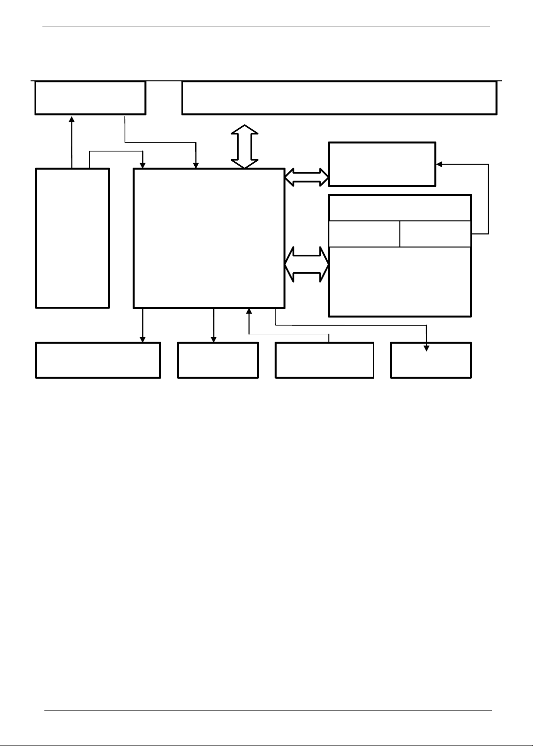
System Specification
Chapter 1

2Chapter 1
Compatibility
Multi-Sound System
•MTS (NTSC), (Stereo/ SAP/ Mono sound system)
Power Source
•Input voltage: 90 ~ 264V, 47 ~ 63Hz
•Input current: 3.47A (Max.)
•Power consumption: 347W (Max.)
•Stand-by: 3W (Max.)
Remote Control
•Multi-function remote control
Speaker
•Internal speaker: 10W x 2 stereo, adjustable volume
Others
•On-screen display adjustment function
•ISP (In System Programming) function available for revising driver easily

Chapter 1 3
System Block and Wiring Diagram
MAIN Board
SPEAKER IR Receiver Key Board
Comconner2
Comconnet1
AV 2
AV 1
I/O Board
D-TunerA-Tuner
HDMI MODULE
DVBT-BOARD
INVERTER
P
ANEL
Module
POWER

4Chapter 1
LCD Main Board Block Diagram

Chapter 1 5
Hardware Specification and Configuration
1. LCD Panel Specification
2. Display Electrical and Functional Specification
2.1 Input and Output Signals
This LCD TV shall have the ability to operate under following range with stable green color of LED indicated.
Panel specification
Outline dimension 983.0 (H) x 576.0 (V) x 52.7 (D)
Display area 42.02 inch
Resolution (pixels) 1366 x 768
Pixel pitch 0.6 (H) x 0.6 (V) mm
Pixel arrangement R, G, B vertical stripe
Display color 16.7 million
Display mode Normally black
Surface treatment Anti-glare and hard coating (3H)
Weight 15000g (typical)
Backlight 20 CCFTs
Input signal 1-channel LVDS
Optimum viewing
direction
6 o’clock
Backlight Power
consumption
174W (typical)
CVBS and Y/C • NTSC (3.58M) color system
TV Systems • NTSC-M (3.58M) system receivable
• VHF/ UHF/ CATV, 181 channels auto-preset
tuning
• Full frequency range from 54MHz to 806MHz
YUV inputs • YCbCr (480i)
• YPbPr (480P, 1080i, 720p)
VGA inputs • Horizontal input frequency range: 30KHz to
70KHz
• Vertical input frequency range: 56Hz to 75Hz
• Max. resolution: 1360 x 768
HDMI inputs • Video mode (480p, 720p, 1080i)
• Horizontal input frequency range: 30KHz to
70KHz
• Vertical input frequency range: 56Hz to 85Hz
• Max resolution: 1920 x 1080 60Hz

6Chapter 1
2.2 Video Input
2.3 Audio Input/Output & Speaker
CVBS Input Signal
Type Analog
Polarity Positive
Level 1 Vp-p (with Sync.)
Impedance 75 +/- 5%
Interface RCA jack, yellow color
S-Video Input Signal
Type Analog
Polarity Positive
Level Y: 1 Vp-p (with Sync.) C: 0.286 Vp-p
Impedance 75 +/- 5%
Interface S-Din, Black color
YUV (YCbCr or YPbPr) Input Signal
Type Analog
Polarity Positive
Level Y: 1 Vp-p (with Sync.) U/V: 0.7 Vp-p
Impedance 75 +/- 5%
Interface RCA Jack, Y: Green color, U: Blue color, V: Red
color
Audio input (for Y/ Pb/ Pr & Video)
Level 500 mVrms
Type Stereo R/L channels
Impedance More than 22K
Interface RCA Jack, R: Red color, L: White color
Audio output (for all source)
Level 500 mVrms (typical)
Type Stereo R/L channels
Impedance Low Impedance
Interface RCA Jack, R: Red color, L: White color
PC line In
Level 500 mVrms
Type Stereo R/L channels
Impedance More than 22K
Interface 3.5mm Stereo jack, Pantone 577C, Lime color
Audio Amplifier and Built-in Speaker
Audio Amp: 8W + 8W (at 500m Vrms input)
Speaker 20W (10W + 10W)
Speaker impedance 4at1KHz
Ω
Ω
Ω
Ω
Ω
Ω

Chapter 1 7
2.4 DVB-T RF Input: Technical Brief for SD DVB-T Module
3. Power Supply Electrical Specification
This power supply for this product is an internal converter with a non-replaceable fuse internally. This converter is
well designed to meet CE mark requirement.
Input voltage and
frequency range
• Operating range of line voltage: AC 90V to 264V,
47Hz to 63Hz
• Power consumption: under 347W
Features Specifications Parameters
Input frequency VHF, UHF Band (Full Band)
Standard DVB-T (ETS 300 744)
Channel Bandwidth 6 MHz, Taiwan Channel
COFDM System 2K, 8K carrier
Hierarchical supported
Demodulation type QPSK, 16QAM, 64QAM
Guard Interval 1/32, 1/16, 1/8, 1/4 active symbol duration
FEC 1/2, 2/3, 3/4, 5/6, 7/8
Terrestrial
Tuner/Demodulator
Antenna power N/A
CPU ZR39151
Transport DVB compliant
Flash memory 2Mbytes
System
System memory 16Mbytes
Bitstream accepted for Video MPEG-1 Video (ISO / IEC 11172-2)
MPEG-2 Video (ISO / IEC 13818-2)
MPEG-2 profiles / levels
Supported
MP@ML, SP@ML, MP@LL
Frame / Field rate 30/ 60 Hz
Video data rate supported 1 ~ 15 Mbps
Aspect ratio 4:3 and 16:9 with Pan and Scan
Video
Output Video for digital programs NTSC
Y/U/V
Format Compliant with ISO11172-3 layer I and layer II
Sampling rate 32, 44.1, 48K Hz
Bit rates Layer I 32-448KHz
Layer II 32-384KHz
Audio
Audio outputs for digital programs Stereo for AL, AR
Communication
Interface
UART TXD / RXD
Bit Rate: up to 115200bps
Rear panel RF IN F-type, Female
Input voltage 5V@ 1A max.,
12V@ 0.26A max.
Power Interface
Power consumption TBD
Interface with LCDTV 36 pins QCI standard interface

8Chapter 1
4. Firmware Specification
4.1 Preset Mode for VGA Input
There are 14 support modes for VGA inputs during the manufacturing process.
4.2 Preset Mode for HDMI Input
There are 20 factory preset modes for HDMI inputs are saved during the manufacturing process.
Line fuse The AC input is fused and becomes electrically
open as a result of an unsafe current condition.
This fuse is inside the power supply converter and
is not user replaceable, and must be returned for
replacement. This fuse is selected to handle inrush
current for all combinations of line voltage and
frequency.
Power on LED location
and type
Power on indicator is easily visible from the front of
the display.
Inverter The inverter which is used to light up backlight of
LCD panel is designed to meet the requirement of
panel’s specification.
Preset
Mode
Pixel
Format
Horizontal
Frequency
(KHz)
Horizontal
Polarity
Vertical
Frequency
(Hz)
Vertical
Polarity Standard
1 720 * 400 31.47 - 70 + VGA
2 640 * 480 31.47 - 60 - VGA
3 640 * 480 37.861 - 72 - VESA
4 640 * 480 37.50 - 75 - VESA
5 640 * 480 43.4 - 85 - VESA
6 800 * 600 35.156 - 56 + VESA
7 800 * 600 37.879 + 60 + VESA
8 800 * 600 48.077 + 72 + VESA
9 800 * 600 46.875 + 75 + VESA
10 800 * 600 53.7 + 85 + VESA
11 1024 * 768 48.363 - 60 - VESA
12 1024 * 768 56.476 - 70 - VESA
13 1024 * 768 60.023 + 75 + VESA
14 1360 * 768 47.7 + 60 + VESA
Preset
Mode Pixel Format Horizontal
Frequency (KHz)
Horizontal
Polarity
Vertical
Frequency (Hz)
Vertical
Polarity Standard
1 640 * 480 60 31.47 - 59.94 -
2 640 * 480 72 37.86 - 72.81 -
3 640 * 480 75 37.5 - 75 -
4 640 * 480 85 43.27 - 85 -
5 800 * 600 56 35.15 - 56.25 +
6 800 * 600 60 37.88 + 60.31 +
7 800 * 600 72 48.07 + 72.18 +

Chapter 1 9
4.3 Power Saving
While VGA is selected to input, this LCD TV is equipped with a power management according to VESA DPMS.
There is a delay of 30 seconds before the transition from on-state to power saving state to avoid unintentionally
entering of a power saving state during display resolution and timing mode changes. During the period of delay,
the LED shall indicate green color and OSD will show No VGA connection. Transition from any power saving
state to another can be instantaneous. The recovery from off-state requires no manual power on.
Note: 1. Sync on means normal operation. 2. Sync off means (1) Hsync: f < 1KHz; (2) duty cycle > 25%; (3)
Vsync: f < 10Hz; (4) duty cycle > 25%.
The power consumption is valid over the specified voltage and frequency range. Power consumption is measured
from AC source. There are no power saving modes for TV, SCART1/2, HDMI1/2, AV3 and AV4 inputs.
8 800 * 600 75 46.87 + 75 +
9 800 * 600 85 53.67 + 85 +
10 1024 * 768 60 48.36 - 60 -
11 1024 * 768 70 56.47 - 70 -
12 1024 * 768 75 60.02 + 75.02 +
13 1024 * 768 85 68.67 + 84.99 +
14 1280 * 768 60
15 1360 * 769 60
16 1280 * 720 50
17 1280 * 720 60 45 60
18 576P 50
19 1920 * 1080i 50
20 1920 * 1080i 60 33.75 60
Mode Hsync Vsync Video Power Indication Recovery time
Power-onOnOnActive<291WGreen -
Stand-by Off On Off < 5W Red < 5s
Suspend On Off Off < 5W Red < 5s
Off-state Off Off Off < 5W Red < 5s
Poweroffxxx<5WDarkTurnon<5s
Preset
Mode Pixel Format Horizontal
Frequency (KHz)
Horizontal
Polarity
Vertical
Frequency (Hz)
Vertical
Polarity Standard

10 Chapter 1
5. VESA DDC
The VGA/ DVI/ HDMI inputs will be capable of continuously transmitting its Extended Display Indentification
(EDID) information using Display Data Channel. It will automatically switch to DDC2 mode if a DDC2 capable host
is detected in accordance with the VESA DDC standard.
In addition, the display can respond to a request for EDID, to be transmitted using DDC2, level B commands. If a
DDC2 capable host is detected by the display, the display will switch to DDC2 communication.
The EDID will contain the manufacture name code QCI, product code, date of manufacture, and serial number.
For complete EDID data structure, please refer to VESA Extended Display Identification Data Standard.
Hardware implementation will be either integrate into micro-controller or be a separate electrical component. EDID
memory will be protected against writing or other corruption through customer-accessible electrical connection and
required communication channels. Password protection, use of an unpublished enable register, or use of direct
electrical connection is acceptable levels of protection provided that the power-on Default State is that disabling
writing. The serial number fields in the EDID will contain a unique identifying numbers among units of the same
model. EDID table is defined as below.
5.1 For VGA Input
5.2 For HDMI Input (Optional)
Product
Revision
0 1 2 3 4 5 6 7 8 9 A B C D E F
0 00 FF FF FF FF FF FF 00 04 72 02 32 00 00 00 00
1 2D DF 01 03 68 46 28 78 E8 DC 10 A2 58 45 9C 25
2 13 49 4B AF EE 00 31 40 45 40 61 40 00 00 00 00
3 00 00 00 00 00 00 69 21 50 B0 51 00 1B 30 40 70
4 36 00 02 90 31 00 00 1E 00 00 00 FD 00 32 55 1E
5 50 08 00 0A 20 20 20 20 20 20 00 00 00 FF 00 30
6 30 30 30 30 0A 20 20 20 20 20 20 20 00 00 00 FC
7 00 61 63 65 72 20 41 54 33 32 30 32 0A 20 00 5A

Chapter 1 11
6. Factory Mode and Factory Default
•Factory mode entrance SOP: press “Volume-“ + “Channel+“ + “Power“ then you can enter the factory
mode.
•Factory default reset SOP: press “Volume-“ + “Channel-“ + “Menu“ and all data will be recalled.
7. Physical Specification
Overall dimensions 794 (H) x 1071 (W) x 311 (D) mm
Overall dimension without
stand
744 (H) x 1071 (W) x 125 (D) mm
Mass of display with cable 34.5 Kg approx.
VESA mounting holes
Compliant to VESA FPMPMI standard, 6 holes,
400 mm x 200 mm (6 mm, 1.0 pitch threaded) in
the rear center for ARM

12 Chapter 1
8. Environment Requirements
Operating 25o+/- 5ofor purity, white point, mis-convergence, luminance
measurements and white uniformity measurement
Operating temperature:
Operating humidity:
0oC to 40oC
10% to 90% (non-condensing)
Storage and Shipping
Storage temperature:
Shipping temperature:
Storage humidity:
Shipping temperature:
-20oC to 60oC
-20oC to 60oC
10% to 90% (non-condensing)

Chapter 1 13
9. Transportation
9.1 Vibration Test
The packaged display shall be capable of passing sinusoidal vibration test below.
•Test conditions
•A duration of 30 minutes in each orientation for the tested unit
•Top and bottom side (z axis)
•Left and right side (x axis)
•Front and rear side (y axis)
9.2 Drop Test
The packaged display shall be capable of passing drop test as specified in following specification without any
measurable degradation in performance or detectable mechanical or cosmetic damage.
Filter: 330 Hz
Dropping way: 1 corner, 3 edges, 6 flats
Dropping height: see the table below
Altitude
Operating altitude:
Shipping altitude:
Storage altitude:
0 to 10,000 feet
0 to 40,000 feet
0 to 40,000 feet
Units tested at an altitude up to 12,000 feet must operate at normal
conditions without exhibiting abnormal behavior such as arcing or
shutdown.
Weight(kg) Corner, edge,
F,R,Btm(cm)
L,R,Up side(cm)
0~9 76 76
9~1 61 61
18~27 46 46
27~45 31 20
45~100 25 15

Chapter 2 14
General Information
This chapter contains step-by-step procedures on how to disassemble the AT4230C series for maintenance and
troubleshooting. To disassemble the TV, you need the following tools:
•Wrist grounding strap and conductive mat for preventing electrostatic discharge
•Small Philips screwdriver
•Philips screwdriver
•Hexagonal screwdriver
•Tweezers
Note: The screws for the different components vary in size. During the disassembly process, please group the
screws with the corresponding components to avoid mismatch when doing assembly. When you remove the
boards, please be careful not to scrape them.
Warning!The module is drived by high voltage. If you need to handle the module during operation or just after
powered off, you must take proper precautions against electric shock and must not touch the drive circuit
portion and metallic part of module within 10 minutes. The capacitors in the drive circuit portion remain
temporarily charged even after the unit is powered off. If the residual voltage is strong enough, it could result in
electric shock. Thus, we strongly suggest that you put on the wrist ground strap and put the component on the
conductive mat or bag. Besides, please keep the unit grounded during the whole process of disassembly and
assembly.
Before You Begin
Before you proceed with the disassembly procedure, make sure that you do the following steps:
1. Turn off the power to the TV and all peripherals.
2. Unplug the AC adaptor and all power and signal cables from the TV.
Machine Disassembly and Replacement
Chapter 2
Table of contents
Other Acer TV manuals