Acnodes DAS-208SA User manual

DAS-208SA Disk Array User Guide
DAS-208SA Disk Array
User Guide
For Serial-ATA to Ultra320 RAID Subsystem
v. 1.0

2
DAS-208SA Disk Array User Guide
The information in this guide may be changed without notice. We assume no
responsibility for any errors which may appear in this guide. Microsoft,
Windows and Windows logo are trademarks of Microsoft Corporation.
Copyright 2004. All rights reserved. No Part of the contents in this guide may
be transmitted or reproduced in any form or by any means without the written
permission of the manufacturer. Printed in Taiwan.
The revision date for this guide is Apr. 30, 2004
Version 1.0
FCC Statement
This equipment has been tested and found to comply with the limits for a Class
A digital device, pursuant to Part 15 of the FCC Rules. These limits are
designed to provide reasonable protection against harmful interference in a
residential installation.
This equipment generates and can radiate radio frequency energy and, if not
installed and used according to the instructions, may cause harmful
interference to radio communications. However, there is no guarantee that
interference will not occur in a particular installation. If this equipment does
cause harmful interference to radio or television reception, which is found by
turning the equipment off and on, the user is encouraged to try to correct the
interference by one or more of the following measures:
--Reorient or relocate the receiving antenna
--Increase the separation between the equipment and device
--Connect the equipment to an outlet other than the receiver
--Consult a dealer or an experienced radio/TV technician for assistance
CE Mark Warning
This is a Class A product. In a domestic environment, this product may cause
radio interference in which case the user may be required to take adequate
measures.

3
DAS-208SA Disk Array User Guide
Chapter 1 General Information
This chapter provides general information of the DAS-208SA Disk Array.
The following topics are covered in this chapter:
◆ Introduction
◆ Key Features & Benefits
◆ Unpacking Your SA-2081 Disk Array
◆ Components of DAS-208SA Disk Array
1.1 Introduction
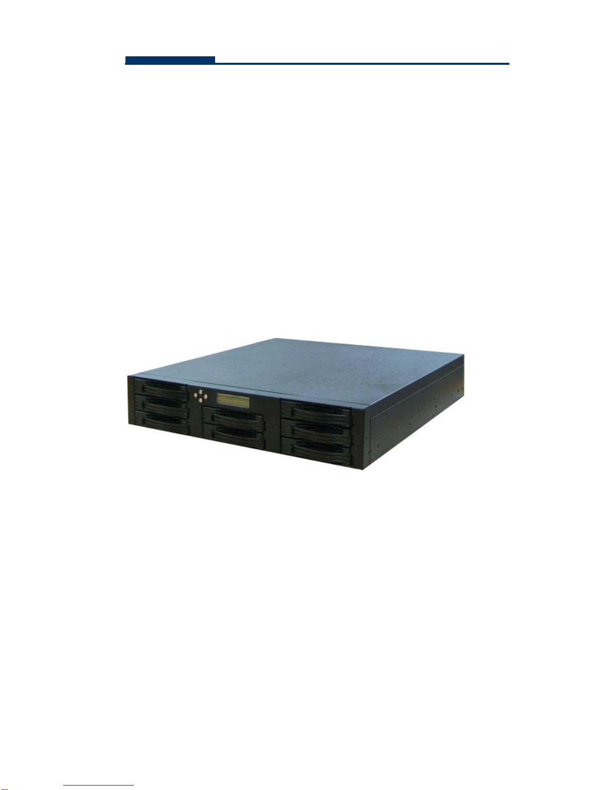
The DAS-208SA is a Serial ATA to Ultra320 SCSI RAID (Redundant Array of
Independent Disks) Disk Array. By implementing sophisticated RAID
technology and unique cache algorithm, this disk array provides the best
protection for the data stored on the array.
And thanks to today’s powerful disk technology, one RAID system can now
provide the capacity more than 1TB in a large cabinet. This offers a wealth of
significant advantages that would be attractive to almost any serious PC users.
Equipped with eight half-height 3.5” disk drives in hot-swappable canisters, the
DAS-208SA Disk Array provides mass data capacity and easy installation for
the individual customers. In addition, this RAID system has dual host channels
and high availability software that ensures 24 hours a day, seven days a week
of nonstop service capability.
Throughout this manual, the DAS-208SA Disk Array may be referred to as
DAS-208SA,or simply as Disk Array.

4
DAS-208SA Disk Array User Guide
1.2 Key Features and Benefits
Advanced LCD display panel
Four easy-to-use push buttons on front panel (▲(up), ▼(down) ,,
ENTER, ESC)
Selectable multiple RAID levels (Level 0,1, 3,5,10, 30, 50, JBOD)
2 Ultra 320 SCSI channels
15 driver bays 1” disk drive
Intel 80321 IO processor
Up to 1GB cache memory
3U compact tower design for more capacity
Cable-less design for better reliability
Swappable design for faster and easier maintenance
Multiple alter design for easier management
1.3 Unpacking Your DAS-208SA
Before removing your DAS-208SA from the shipping carton, you should
virtually inspect the physical condition of the container. The package of
DAS-208SA should appear in good condition when you first received it. If any
damaged found, do not remove the components. Contact the place of
purchase for further instructions.
If the shipping container appears to be in good condition, unpack it and verify
that the DAS-208SA and accessories are all there and in good condition.
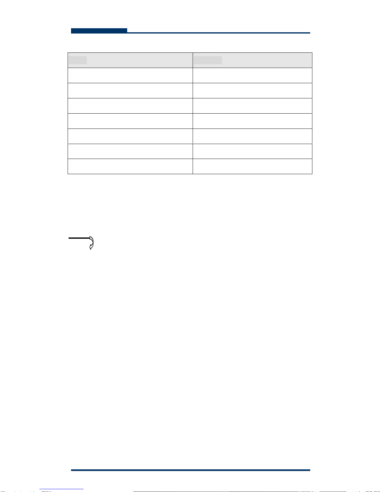
Your DAS-208SA package should contain the following items:

5
DAS-208SA Disk Array User Guide
If any item is missing or damaged, please contact the place of purchase for
assistance. Retain the shipping container and packing material for reuse.
Before you begin to use your DAS-208SA, read section 1.4
Components of the DAS-208SA to learn more about the major
components or your RAID Disk Array.
Items Quantity
DAS-208SA unit 1
Drive Canister 8
Ultra320 SCSI Cable 1
Power Cord 2
RS-232 Cable 1
User Menu CD 1
Spare screws 40
Note

6
DAS-208SA Disk Array User Guide
1.4 Components of the DAS-208SA
This section describes the major components of the DAS-208SA, including its
front panel, LED display panel and rear panel. Read this section before you
start to use your RAID Disk Array Subsystem.
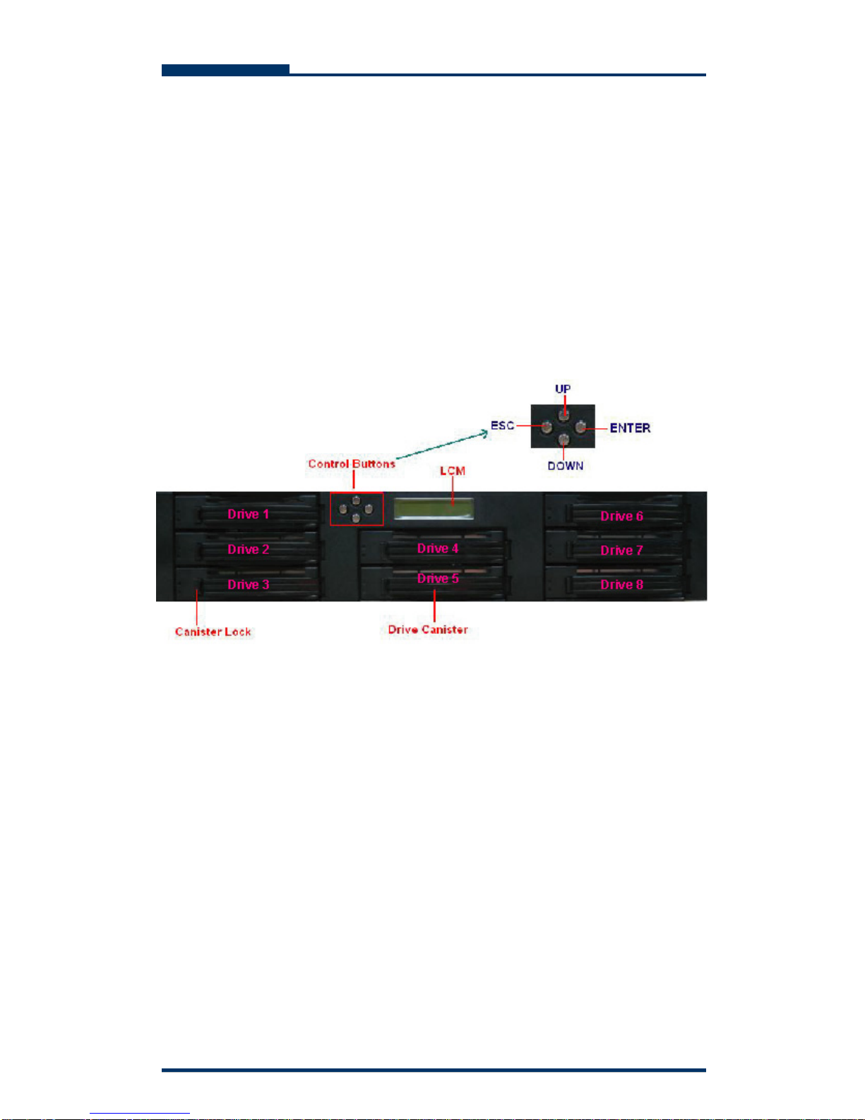
1.4.1 The Front Panel
Please refer to Figure 1-1 for the front panel of DAS-208SA Disk Array in the
following page.
1.4.2 LCD Display Panel and Control Buttons
The control panel of the DAS-208SA consists of a LCD display panel and 4
control buttons. This is where you will check the configuration and status of the
disk array. Figure1-2 shows the general information, such as RAID status,
thermograph, and fan temperature of the Disk Array. Meanwhile, control
buttons allow you to use Up (▲) and Down (▼) arrow keys to go through the
information on the LCM display screen. The ENTER button is used to enter the
option you have selected and the ESC button can take you back to the
previous menu. Please refer to Table 1-1 for detailed information of each status.

7
DAS-208SA Disk Array User Guide
For the status of each hard disk in Disk Array, please refer to Table 1-2.
Meanwhile, for fans and power error messages, alarm and indicators shown
on the LCD, please refer Table 1-3.
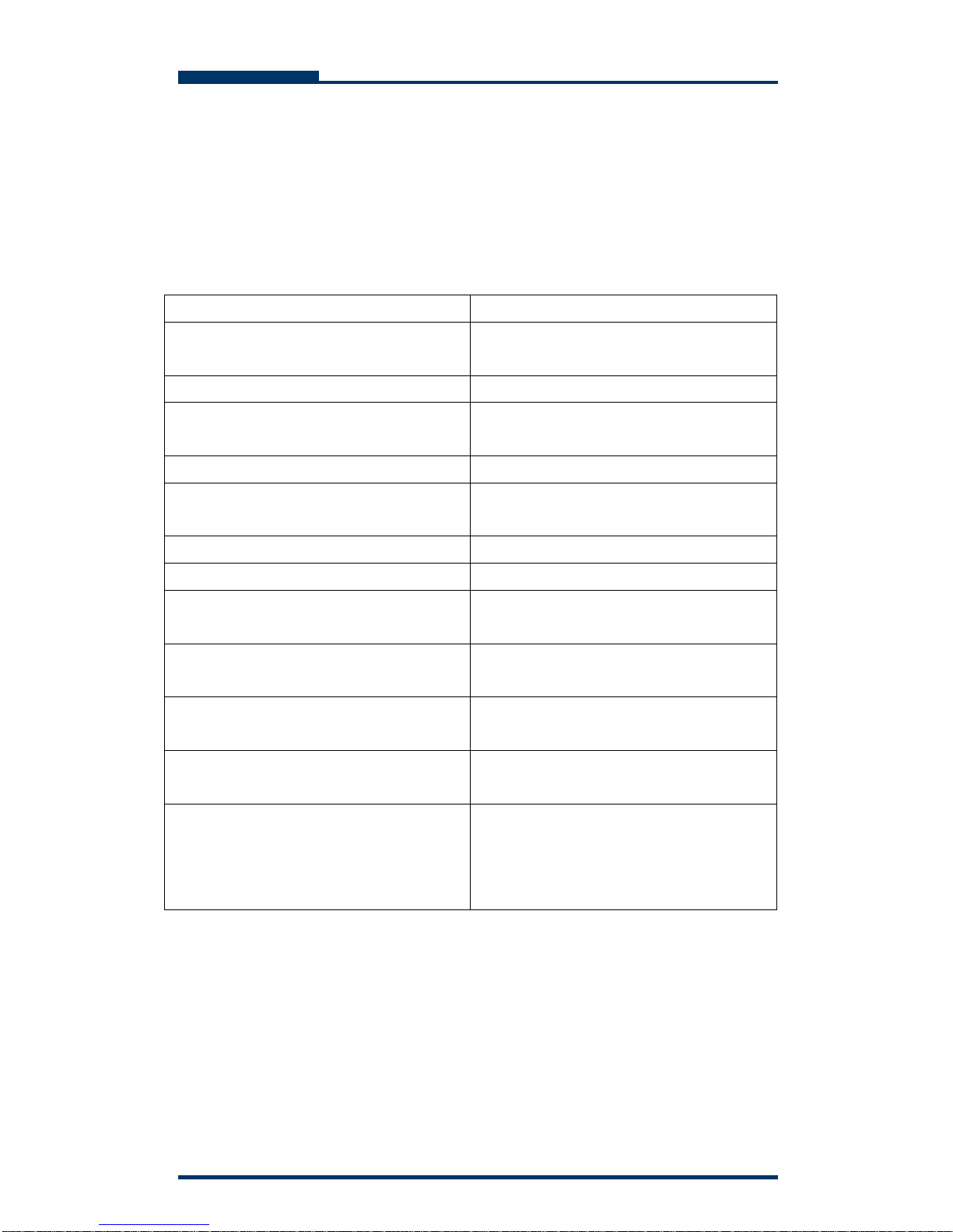
Table 1-1
Items Status Description
DAS-208SA Disk Array Indicates the model name of the
product
Installed Memory 128 Mbytes Indicates the capacity of the memory
CPU Type: 80321 4 Ultra320 Indicates the CPU model and
interface
Firmware Version v. 1.0 Indicates the version of the firmware
Serial Number: xxxxxxxxxxxxx Indicates the serial number of the
RAID controller
FAN1 RPM*Indicates the speed of Fan 1
FAN2 RPM*Indicates the speed of Fan 2
Temp 1 Indicates the temperature of the
upper part of the backplane.
Temp 2 Indicates the temperature of the
central part of the backplane.
Temp 3 Indicates the temperature of the
bottom part of the backplane.
ZzZZZzzz Indicates the random display when
parity checking
z A single “z” appearing at the right end
of the LCD panel (eg. 11112222z )
indicates that memory is not enough
during read & write.
*Please note that RPM under 2200 will be considered fan failure; replace
the fan immediately for better performance.

8
DAS-208SA Disk Array User Guide
Table 1-2
Hard Disk Status Letter shown on LCD
JBOD J
Disk Offline X
Disk Rebuilding A
Disk Removed R
Spare Disk S
Disk Initializing I
RAID Set 1 1
RAID Set 2 2
RAID Set 3 3
RAID Set 4 4
Read/Write W
Table 1-3
Item Error messages shown on LCD
LCD show Fan module#1 fail “Fan1 Failed”
LCD show Fan module#2 fail “Fan2 Failed”
LCD show power module#1 fail “PW1 Malfunction”
LCD show power module#2 fail “PW2 Malfunction”

9
DAS-208SA Disk Array User Guide
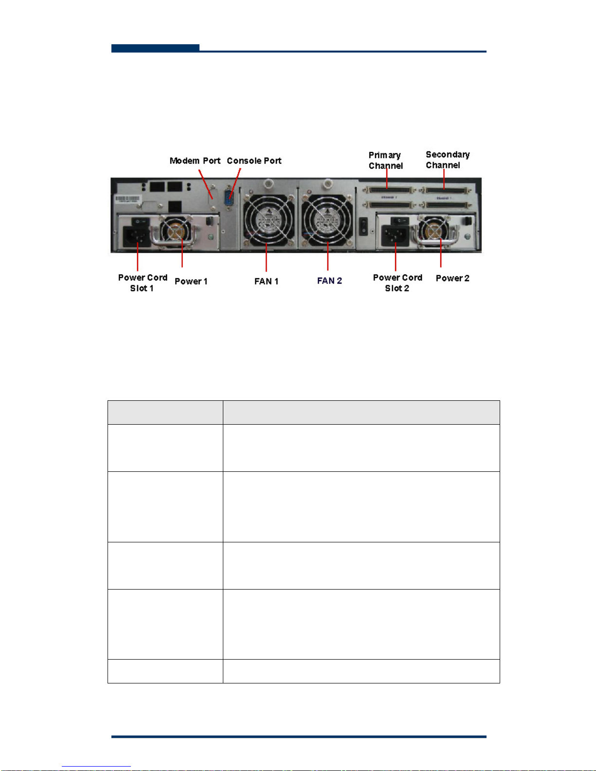
1.4.3 The Rear Panel
The rear panel of DAS-208SA is shown below.
Refer to Table 1-4 for detailed description of each part on the rear panel of
DAS-208SA.
Table 1-4
Part Description
Modem port This is where you can connect your disk array to a
modem.
Console port This is a RS-232 serial port, allowing you to connect to a
terminal or a PC. You may configure this disk array, and
upgrade the firmware and RAID.
Primary and
Secondary Channels
DAS-208SA has two host channels—primary and
secondary—to allow you to connect to SCSI devices.
Fan There are 2 fans located at the rear of the system unit.
They are designed to provide good airflow and heat
dissipation.
Power The disk array comes with 2 hot-swappable power

10
DAS-208SA Disk Array User Guide
supplies located at the rear of the subsystem. If two of
the power supplies are in use and one fails to function,
an audible alarm will warn you of the power failure.
Power Cord Slot These are where you connect power cords to power
socket.

11
DAS-208SA Disk Array User Guide
Chapter 2 Hardware Installation
This chapter discusses the basic operational installation and the Disk Drive
installation.
The following topics are covered in this chapter:
Preparing for the Installation
Disk Drive Installation
Table and Shelf Installation
Rack-Mount Installation
Tower Conversion kit Installation
2.1 Preparing for the Installation
If you will be connecting your DAS-208SA Disk Array to the computer using a
SCSI adapter, installed the adapter(s) in an available slot in the computer prior
to beginning the DAS-208SA installation. See your operating system manuals
for the configuration procedures for the host bus adapter.
2.1.2 Terminating Disk Drive Channels
All SCSI buses must be terminated at each end. Termination absorbs electrical
signals and prevents those signals from bouncing back along the bus and
causing interference.
The SCSI drive channels of the DAS-208SA have been terminated inside the
chassis on the back plane. There is no need to terminate the disk drives!

12
DAS-208SA Disk Array User Guide
2.1.3 Connecting the DAS-208SA
DAS-208SA can be connected to the host computer via 2 Ultra320 SCSI ports.
2.1.4 Host Bus SCSI ID Assignment
You may assign any SCSI ID to the host channel. The range of SCSI IDs on a
Wide SCSI bus starts from 0 to 15. You can use the LCD panel or a terminal to
set the host channel ID. (Refer to Section 3.1 Configuration Methods for more
information.) Be sure to assign an ID that does not conflict with any other
devices on the host bus as well as the host adapter.
2.1.5 Host Bus Termination
The disk array is shipped with host channel buses terminated. If the disk array
is not the last device on the host bus, you must turn off termination from the
LCD panel or a terminal.
2.1.6 Back Plane
The back plane of the DAS-208SA is specifically designed to furnish the
stability of voltage and provide the reliability for disk array.
2.1.7 Connecting the Power Cord
Before you connect the power cords to the power supplies, make sure the
power supplies have been firmly seated inside the DAS-208SA Disk Array.
2.1.8 Uninterruptible Power Supplies
To insure the integrity of the data stored on a RAID array, we strongly
recommend connecting the DAS-208SA Disk Array to an external UPS.

13
DAS-208SA Disk Array User Guide
2.2 Disk Drive Installation
Any 3.5“ Serial-ATA hard disk, half-height 1” (2.54cm) SCA connector can be
installed into the canister of DAS-208SA.
Figure 2-1 shows the disk drive and canister of DAS-208SA Disk Array.
Figure 2-1 Disk Drive and Canister

14
DAS-208SA Disk Array User Guide
Second, use four screws to fasten the drive to the drive canister. Please note
that you fasten the drive at the right location. (See Figure 2-2)
Figure 2-2
DAS-208SA Disk Array provides eight slots that enable you to utilize eight disk
drives. Insert each slot to the drive canister of Disk Array; system will
automatically check all available disks.

15
DAS-208SA Disk Array User Guide
Chapter 3 Configuration
FASTORA DAS-T8CA can be configured via its LCD panel or via a terminal.
This chapter will discuss the configuration methods and the detailed
information about the operation modes.
This chapter covers the following topics:
Configuring Through the LCD Display Panel
Configuring Through a Terminal
Operation Modes
Main Menu
3.1 Configuring Through the LCD Display Panel
The LCD Panel consists of a two lines 16-character LCD display, two LED
indicators, four push buttons, and a reset button, allowing users to configure
and monitor the operation of the disk array. A menu of configuration options will
appear on the display. By using the (▲) Up arrow, (▼) Down arrow, ESC, and
ENTER buttons, users can traverse various menu levels and configure his
desired parameters.
The function of the buttons is descried as follows:
(▲) Up Arrow To scroll upward through the menu items;
(▼) Down Arrow To scroll downward through the menu items;
Enter To select a menu item, open a sub-menu, and select a value
ESC To exit a sub-menu and returns to the previous menu.

16
DAS-208SA Disk Array User Guide
If you wish to start with the LCD display panel as quickly as
possible, refer to Chapter 4.1.1Quick Setup via LCD Display
Panel to configure the disk array.
3.2 Configuring Through a Terminal
The LCD control panel allows the exploration of all configurable features of the
disk array. However, the frame of the LCD panel only allows a few messages
of output. In this case, a very limited amount of information can be displayed at
a given time on the LCD display panel.
In fact, using a terminal to configure your disk array will be exactly the same as
using the LCD display to do the configuration. Unlike the LCD display that can
only show 2 lines of the configuration information, a terminal, connected via a
modem or direct serial interface, displays all information pertinent to a particular
function on a larger terminal screen. In addition, the help information, which is
impractical to be shown on the LCD panel, is also available on the terminal.
3.2.1 Connecting a Terminal
Located at the rear of the disk array, a RS-232 connector, marked as Console,
can be used to support the local terminal access. When connecting a terminal
to the disk array, make sure you have attached the supplied RS-232cable to
the right Console connector. Note that you should set up the communication
parameters before using this terminal. To start up:
1. Plug one end of the supplied RS-232 cable to the port marked as Console
at the rear of the disk array.
2. Connect one end of the RS-232 cable to the COM port of your terminal or
PC.
3. Run an equivalent program of the terminal.
4. Change the setting of the terminal to match the default settings of the
Note

17
DAS-208SA Disk Array User Guide
FASTORADAS-T8CA, namely:
Baud rate: 115,200
Data bit: 8
Stop bit: 1
Parity: None
Flow Control: None
You shall see a pop-up screen indicating that the connection has been setup
successfully. Then, you may configure the disk array with your terminal. Refer to
section 3.2.3 Control Key Definition under ANSI Terminal to learn the control keys for
terminal emulation.
Please note that if you wish to start to configure with your terminal as quickly
as possible, you may refer to Section 4.1.2 Quick setup via Terminal
Configuration.
3.2.2 Using PC for Terminal Emulation
If you do not have a dedicated terminal, you can still use a PC configured as a
terminal, running a terminal emulation program. Microsoft Windows and
Windows 95 both have built-in terminal emulation support. Please select ANSI
terminal as the terminal type for the terminal emulation. You can also use other
terminal emulation programs such as KERMIT or VTERM. If you cannot see
anything on the screen after the session has been established, press TAB key
followed by Ctrl-D key combination to refresh the screen.
Follow the same steps discussed in section 3.2.1 Connecting a Terminal to
connect your PC to the disk array.

18
DAS-208SA Disk Array User Guide
3.2.3 Control Key Definition under ANSI Terminal
Using ANSI terminal display, the following keys are supported:
A- used to scroll upward through the menu items
Z- used to scroll downward through the menu items
ENTER - used to select a menu item, open a sub-menu, and select a value
ESC - used to exit a sub-menu and return to the previous menu
TAB - used to switch between windows
The rest of the alphanumeric keys are also supported for password input and
when prompted for Yes or No input.
3.3 Operation Modes
DAS-208SA Disk Array has three operation modes: Self-Diagnostic Mode,
Operation Mode, and Configuration Mode. We will discuss each of the RAID
disk array operation mode in the following sections.
3.3.1 Self Diagnostic Mode
To ensure flawless operation, the disk array has a built-in self-diagnostic utility.
Self-diagnostics will be performed automatically upon power up of the disk
array or right after you restart the unit. In this mode of operation, all
components will be tested. If any problem occurred, it will report to the user.
The Self-Diagnostic mode runs three major diagnostics. The first diagnostic
tests the CPU and supporting the core logic chips, internal bus, memory, SCSI
controllers, and RS-232 controllers. The second diagnostic tests the presence
of disks on each individual disk channel. It also checks the functionality of the
disks found. The last diagnostic tests RAID functionality.

19
DAS-208SA Disk Array User Guide
3.3.2 Operation Mode
Operation mode continuously reports the operating status of the disk array and
the drives connected to it. During normal operation, the LCD display will
continuously show the status of all the major components. Note that the last
character on the second line of the LCD panel with a tiny square moving up
and down, to indicate that the DAS-208SA Disk Array is in operation.
3.3.3 Configuration Mode
Configuration mode is used to modify the settings of disk array. Users can
configure theDAS-208SA either through the LCD panel or via a terminal. Note
that you are entering the configuration mode whenever you are pressing the
SEL button during the Operation Mode. If you wish to enter to the configuration
mode from a terminal, simply use the “TAB” key to take you to your desired
mode.
1. You cannot enter the configuration Mode from LCD panel and
Terminal at the same time.
2. You will be prompted to enter your password if the
password-checking feature is enabled. Provide the correct password
to continue your configuration.
Unless the disk array is running the self-diagnose mode, you may select any of
the configuration modes at any time. The configuration mode of DAS-208SA is
completely menu-driven for the ease of use. And the menu options allow you to
fine-tune disk array to your specific configuration.

20
DAS-208SA Disk Array User Guide
3.4 Main Menu
The main menu under Configuration mode consists of the following menus:
Quick Setup,RAID Parameters, SCSI Parameters, RS-232 Parameters,
System Parameters, NVRAM, and RAID Functions. We will navigate the
main tree in this section. Figure 3-1 shows the main menu screen when
configuring through a terminal.
Figure 3-1
Table of contents