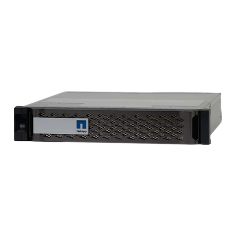
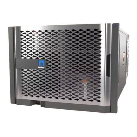
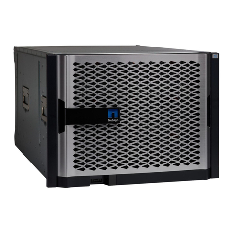
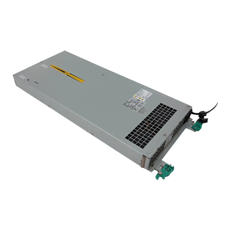
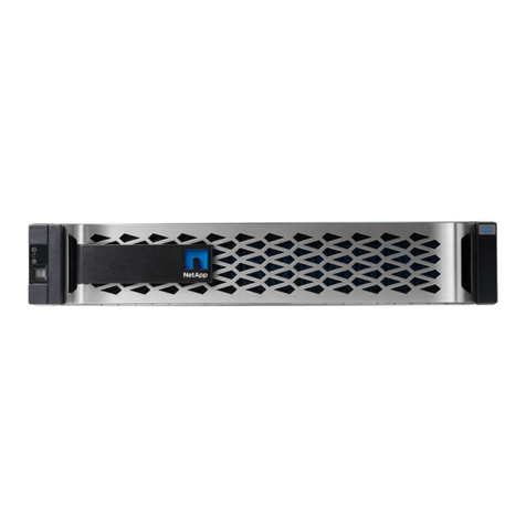
NetApp AFF A700s User manual

AFF A700s systems
ONTAP Systems
NetApp
January 28, 2022
This PDF was generated from https://docs.netapp.com/us-en/ontap-systems/a700s/install-worksheet-
linkout.html on January 28, 2022. Always check docs.netapp.com for the latest.

Table of Contents
AFF A700s System Documentation . . . . . . . . . . . . . . . . . . . . . . . . . . . . . . . . . . . . . . . . . . . . . . . . . . . . . . . . . . . Ê1
Install and setup . . . . . . . . . . . . . . . . . . . . . . . . . . . . . . . . . . . . . . . . . . . . . . . . . . . . . . . . . . . . . . . . . . . . . . . . Ê1
Maintain . . . . . . . . . . . . . . . . . . . . . . . . . . . . . . . . . . . . . . . . . . . . . . . . . . . . . . . . . . . . . . . . . . . . . . . . . . . . . . Ê1

AFF A700s System Documentation
Install and setup
Cluster configuration worksheet - AFF A700s
You can use the worksheet to gather and record your site-specific IP addresses and other information required
when configuring an ONTAP cluster.
Cluster Configuration Worksheet
Start here: Choose your installation and setup experience
You can choose from different content formats to guide you through installing and setting
up your new storage system.
•Quick steps
A printable PDF of step-by-step instructions with live links to additional content.
•Video steps
Video step-by-step instructions.
Installation and setup PDF poster - AFF A700s
You can use the PDF poster to install and set up your new system. The PDF poster provides step-by-step
instructions with live links to additional content.
AFF A700s Installation and Setup Instructions
Installation and setup video - AFF A700s
The following video shows end-to-end software configuration for systems running ONTAP 9.2.
AFF A700s Setup Video
Maintain
Boot media
Replacing the boot media - AFF A700s
The primary boot media stores the ONTAP boot image that the system uses when it
boots. You can restore the primary boot media image by using the ONTAP image on the
secondary boot media, or if necessary, by using a USB flash drive.
If your secondary boot media has failed or is missing the image.tgz file, you must restore the primary boot
media using a USB flash drive. The drive must be formatted to FAT32 and must have the appropriate amount
of storage to hold the image_xxx.tgz file.
1

•The replacement process restores the var file system from the secondary boot media or USB flash drive to
the primary boot media.
•You must replace the failed component with a replacement FRU component you received from your
provider.
•It is important that you apply the commands in these steps on the correct node:
◦The impaired node is the node on which you are performing maintenance.
◦The healthy node is the HA partner of the impaired node.
Check onboard encryption keys as needed - AFF A700s
Prior to shutting down the impaired node and checking the status of the onboard
encryption keys, you must check the status of the impaired node, disable automatic
giveback, and check what version of ONTAP the system is running.
If you have a cluster with more than two nodes, it must be in quorum. If the cluster is not in quorum or a healthy
node shows false for eligibility and health, you must correct the issue before shutting down the impaired node;
see the NetApp Encryption overview with the CLI.
Steps
1. Check the status of the impaired node:
◦If the impaired node is at the login prompt, log in as admin.
◦If the impaired node is at the LOADER prompt and is part of HA configuration, log in as admin on the
healthy node.
◦If the impaired node is in a standalone configuration and at LOADER prompt, contact
mysupport.netapp.com.
2. If AutoSupport is enabled, suppress automatic case creation by invoking an AutoSupport message:
system node autosupport invoke -node * -type all -message
MAINT=number_of_hours_downh
The following AutoSupport message suppresses automatic case creation for two hours: cluster1:*>
system node autosupport invoke -node * -type all -message MAINT=2h
3. Check the version of ONTAP the system is running on the impaired node if up, or on the partner node if the
impaired node is down, using the version -v command:
◦If <lno-DARE> is displayed in the command output, the system does not support NVE, proceed to shut
down the controller.
◦If <lno-DARE> is not displayed in the command output, and the system is running ONTAP 9.5, go to
[Option 1: Checking NVE or NSE on systems running ONTAP 9.5 and earlier].
◦If <lno-DARE> is not displayed in the command output, and the system is running ONTAP 9.6 or later,
go to [Option 2: Checking NVE or NSE on systems running ONTAP 9.6 and later].
4. If the impaired node is part of an HA configuration, disable automatic giveback from the healthy node:
storage failover modify -node local -auto-giveback false or storage failover
modify -node local -auto-giveback-after-panic false
Option 1: Check NVE or NSE on systems running ONTAP 9.5 and earlier
Before shutting down the impaired node, you need to check whether the system has
2
either NetApp Volume Encryption (NVE) or NetApp Storage Encryption (NSE) enabled. If
so, you need to verify the configuration.
Steps
1. Connect the console cable to the impaired node.
2. Check whether NVE is configured for any volumes in the cluster: volume show -is-encrypted true
If any volumes are listed in the output, NVE is configured and you need to verify the NVE configuration. If
no volumes are listed, check whether NSE is configured.
3. Check whether NSE is configured: storage encryption disk show
◦If the command output lists the drive details with Mode & Key ID information, NSE is configured and
you need to verify the NSE configuration.
◦If NVE and NSE are not configured, it’s safe to shut down the impaired node.
Verify NVE configuration
Steps
1. Display the key IDs of the authentication keys that are stored on the key management servers: security
key-manager query
◦If the Restored column displays yes and all key managers display available, it’s safe to shut down
the impaired node.
◦If the Restored column displays anything other than yes, or if any key manager displays
unavailable, you need to complete some additional steps.
◦If you see the message This command is not supported when onboard key management is enabled,
you need to complete some other additional steps.
2. If the Restored column displayed anything other than yes, or if any key manager displayed
unavailable:
a. Retrieve and restore all authentication keys and associated key IDs: security key-manager
restore -address *
If the command fails, contact NetApp Support.
mysupport.netapp.com
b. Verify that the Restored column displays yes for all authentication keys and that all key managers
display available: security key-manager query
c. Shut down the impaired node.
3. If you saw the message This command is not supported when onboard key management is enabled,
display the keys stored in the onboard key manager: security key-manager key show -detail
a. If the Restored column displays yes manually back up the onboard key management information:
▪Go to advanced privilege mode and enter ywhen prompted to continue: set -priv advanced
▪Enter the command to display the OKM backup information: security key-manager backup
show
▪Copy the contents of the backup information to a separate file or your log file. You’ll need it in
3

disaster scenarios where you might need to manually recover OKM.
▪Return to admin mode: set -priv admin
▪Shut down the impaired node.
b. If the Restored column displays anything other than yes:
▪Run the key-manager setup wizard: security key-manager setup -node
target/impaired node name
Enter the customer’s onboard key management passphrase at the prompt. If the
passphrase cannot be provided, contact mysupport.netapp.com
▪Verify that the Restored column displays yes for all authentication key: security key-
manager key show -detail
▪Go to advanced privilege mode and enter ywhen prompted to continue: set -priv advanced
▪Enter the command to display the OKM backup information: security key-manager backup
show
▪Copy the contents of the backup information to a separate file or your log file. You’ll need it in
disaster scenarios where you might need to manually recover OKM.
▪Return to admin mode: set -priv admin
▪You can safely shutdown the node.
Verify NSE configuration
Steps
1. Display the key IDs of the authentication keys that are stored on the key management servers: security
key-manager query
◦If the Restored column displays yes and all key managers display available, it’s safe to shut down
the impaired node.
◦If the Restored column displays anything other than yes, or if any key manager displays
unavailable, you need to complete some additional steps.
◦If you see the message This command is not supported when onboard key management is enabled,
you need to complete some other additional steps
2. If the Restored column displayed anything other than yes, or if any key manager displayed
unavailable:
a. Retrieve and restore all authentication keys and associated key IDs: security key-manager
restore -address *
If the command fails, contact NetApp Support.
mysupport.netapp.com
b. Verify that the Restored column displays yes for all authentication keys and that all key managers
display available: security key-manager query
c. Shut down the impaired node.
3. If you saw the message This command is not supported when onboard key management is enabled,
4

display the keys stored in the onboard key manager: security key-manager key show -detail
a. If the Restored column displays yes, manually back up the onboard key management information:
▪Go to advanced privilege mode and enter ywhen prompted to continue: set -priv advanced
▪Enter the command to display the OKM backup information: security key-manager backup
show
▪Copy the contents of the backup information to a separate file or your log file. You’ll need it in
disaster scenarios where you might need to manually recover OKM.
▪Return to admin mode: set -priv admin
▪Shut down the impaired node.
b. If the Restored column displays anything other than yes:
▪Run the key-manager setup wizard: security key-manager setup -node
target/impaired node name
Enter the customer’s OKM passphrase at the prompt. If the passphrase cannot be
provided, contact mysupport.netapp.com
▪Verify that the Restored column shows yes for all authentication keys: security key-
manager key show -detail
▪Go to advanced privilege mode and enter ywhen prompted to continue: set -priv advanced
▪Enter the command to back up the OKM information: security key-manager backup show
Make sure that OKM information is saved in your log file. This information will be
needed in disaster scenarios where OKM might need to be manually recovered.
▪Copy the contents of the backup information to a separate file or your log. You’ll need it in disaster
scenarios where you might need to manually recover OKM.
▪Return to admin mode: set -priv admin
▪You can safely shut down the node.
Option 2: Check NVE or NSE on systems running ONTAP 9.6 and later
Before shutting down the impaired node, you need to verify whether the system has
either NetApp Volume Encryption (NVE) or NetApp Storage Encryption (NSE) enabled. If
so, you need to verify the configuration.
1. Verify whether NVE is configured for any volumes in the cluster: volume show -is-encrypted true
If any volumes are listed in the output, NVE is configured and you need to verify the NVE configuration. If
no volumes are listed, check whether NSE is configured.
2. Verify whether NSE is configured: storage encryption disk show
◦If the command output lists the drive details with Mode & Key ID information, NSE is configured and
you need to verify the NSE configuration.
◦If no disks are shown, NSE is not configured.
5

◦If NVE and NSE are not configured, it’s safe to shut down the impaired node.
Verify NVE configuration
1. Display the key IDs of the authentication keys that are stored on the key management servers: security
key-manager query
◦If the Key Manager type displays external and the Restored column displays yes, it’s safe to shut
down the impaired node.
◦If the Key Manager type displays onboard and the Restored column displays yes, you need to
complete some additional steps.
◦If the Key Manager type displays external and the Restored column displays anything other than
yes, you need to complete some additional steps.
◦If the Key Manager type displays onboard and the Restored column displays anything other than
yes, you need to complete some additional steps.
2. If the Key Manager type displays onboard and the Restored column displays yes, manually back up
the OKM information:
a. Go to advanced privilege mode and enter ywhen prompted to continue: set -priv advanced
b. Enter the command to display the key management information: security key-manager onboard
show-backup
c. Copy the contents of the backup information to a separate file or your log file. You’ll need it in disaster
scenarios where you might need to manually recover OKM.
d. Return to admin mode: set -priv admin
e. Shut down the impaired node.
3. If the Key Manager type displays external and the Restored column displays anything other than
yes:
a. Restore the external key management authentication keys to all nodes in the cluster: security key-
manager external restore
If the command fails, contact NetApp Support.
mysupport.netapp.com
b. Verify that the Restored column equals yes for all authentication keys: security key-manager
key query
c. Shut down the impaired node.
4. If the Key Manager type displays onboard and the Restored column displays anything other than yes:
a. Enter the onboard security key-manager sync command: security key-manager onboard sync
Enter the customer’s onboard key management passphrase at the prompt. If the
passphrase cannot be provided, contact NetApp Support. mysupport.netapp.com
b. Verify the Restored column shows yes for all authentication keys: security key-manager key
query
c. Verify that the Key Manager type shows onboard, and then manually back up the OKM information.
6

d. Go to advanced privilege mode and enter ywhen prompted to continue: set -priv advanced
e. Enter the command to display the key management backup information: security key-manager
onboard show-backup
f. Copy the contents of the backup information to a separate file or your log file. You’ll need it in disaster
scenarios where you might need to manually recover OKM.
g. Return to admin mode: set -priv admin
h. You can safely shut down the node.
Verify NSE configuration
1. Display the key IDs of the authentication keys that are stored on the key management servers: security
key-manager query
◦If the Key Manager type displays external and the Restored column displays yes, it’s safe to shut
down the impaired node.
◦If the Key Manager type displays onboard and the Restored column displays yes, you need to
complete some additional steps.
◦If the Key Manager type displays external and the Restored column displays anything other than
yes, you need to complete some additional steps.
◦If the Key Manager type displays external and the Restored column displays anything other than
yes, you need to complete some additional steps.
2. If the Key Manager type displays onboard and the Restored column displays yes, manually back up
the OKM information:
a. Go to advanced privilege mode and enter ywhen prompted to continue: set -priv advanced
b. Enter the command to display the key management information: security key-manager onboard
show-backup
c. Copy the contents of the backup information to a separate file or your log file. You’ll need it in disaster
scenarios where you might need to manually recover OKM.
d. Return to admin mode: set -priv admin
e. You can safely shut down the node.
3. If the Key Manager type displays external and the Restored column displays anything other than
yes:
a. Enter the onboard security key-manager sync command: security key-manager external
sync
If the command fails, contact NetApp Support.
mysupport.netapp.com
b. Verify that the Restored column equals yes for all authentication keys: security key-manager
key query
c. You can safely shut down the node.
4. If the Key Manager type displays onboard and the Restored column displays anything other than yes:
a. Enter the onboard security key-manager sync command: security key-manager onboard sync
7

Enter the customer’s onboard key management passphrase at the prompt. If the passphrase cannot be
provided, contact NetApp Support.
mysupport.netapp.com
b. Verify the Restored column shows yes for all authentication keys: security key-manager key
query
c. Verify that the Key Manager type shows onboard, and then manually back up the OKM information.
d. Go to advanced privilege mode and enter ywhen prompted to continue: set -priv advanced
e. Enter the command to display the key management backup information: security key-manager
onboard show-backup
f. Copy the contents of the backup information to a separate file or your log file. You’ll need it in disaster
scenarios where you might need to manually recover OKM.
g. Return to admin mode: set -priv admin
h. You can safely shut down the node.
Shut down the node - AFF A700s
After completing the NVE or NSE tasks, you need to complete the shutdown of the
impaired node.
Steps
1. If the impaired node isn’t at the LOADER prompt:
If the impaired node displays… Then…
Waiting for giveback... Press Ctrl-C, and then respond ywhen prompted.
System prompt or password
prompt (enter system password)
Take over or halt the impaired node from the healthy node: storage
failover takeover -ofnode impaired_node_name
+
When the impaired node shows Waiting for giveback…, press Ctrl-C,
and then respond y.
+
2. From the LOADER prompt, enter: printenv to capture all boot environmental variables. Save the output
to your log file.
This command may not work if the boot device is corrupted or non-functional.
Remove the controller module and replace the boot media - AFF A700s
You must remove the controller module from the chassis, open it, and then replace the
failed boot media.
8

Step 1: Remove the controller module
You must remove the controller module from the chassis when you replace the controller
module or replace a component inside the controller module.
1. If you are not already grounded, properly ground yourself.
2. Loosen the hook and loop strap binding the cables to the cable management device, and then unplug the
system cables and SFPs (if needed) from the controller module, keeping track of where the cables were
connected.
Leave the cables in the cable management device so that when you reinstall the cable management
device, the cables are organized.
3. Unplug the controller module power supply from the source, and then unplug the cable from the power
supply.
4. Remove the cable management device from the controller module and set it aside.
5. Press down on both of the locking latches, and then rotate both latches downward at the same time.
The controller module moves slightly out of the chassis.
Locking latch
Locking pin
1. Slide the controller module out of the chassis.
Make sure that you support the bottom of the controller module as you slide it out of the chassis.
9

2. Place the controller module on a stable, flat surface, and then open the air duct:
a. Press in the locking tabs on the sides of the air duct toward the middle of the controller module.
b. Slide the air duct toward the fan modules, and then rotate it upward to its completely open position.
Air duct locking tabs
Risers
Air duct
Step 2: Replace the boot media - AFF A700s
You must locate the failed boot media in the controller module by removing the middle
PCIe module on the controller module, locate the failed boot media by the lit LED near
the boot media, and then replace the boot media.
You need a Phillips head screwdriver to remove the screw that holds the boot media in place.
1. If you are not already grounded, properly ground yourself.
2. Locate the boot media:
a. Open the air duct, if needed.
b. If needed, remove Riser 2, the middle PCIe module, by unlocking the locking latch and then removing
the riser from the controller module.
10

Air duct
Riser 2 (middle PCIe module)
Boot media screw
Boot media
3. Locate the failed boot media by the lit LED on the controller module motherboard.
4. Remove the boot media from the controller module:
a. Using a #1 Phillips head screwdriver, remove the screw holding down the boot media and set the screw
aside in a safe place.
b. Grasping the sides of the boot media, gently rotate the boot media up, and then pull the boot media
straight out of the socket and set it aside.
5. Align the edges of the replacement boot media with the boot media socket, and then gently push it into the
socket.
6. Check the boot media to make sure that it is seated squarely and completely in the socket.
If necessary, remove the boot media and reseat it into the socket.
7. Rotate the boot media down until it is flush with the motherboard.
8. Secure the boot media in place by using the screw.
11

Do not over-tighten the screw. Doing so might crack the boot media circuit board.
9. Reinstall the riser into the controller module.
10. Close the air duct:
a. Rotate the air duct downward.
b. Slide the air duct toward the risers until it clicks into place.
Transfer the boot image to the boot media - AFF A700s
You can install the system image to the replacement boot media using by using either the
image on second boot media installed in the controller module, the primary method to
restore the system image, or by transferring the boot image to the boot media using a
USB flash drive when the secondary boot media restore failed or if the image.tgz file is
not found on the secondary boot media.
Option 1: Transfer files to the boot media using backup recovery from the second boot media
You can install the system image to the replacement boot media using the image on
second boot media installed in the controller module. This is the primary method for
transferring the boot media files to the replacement boot media in systems with two boot
media in the controller module.
The image on the secondary boot media must contain an image.tgz file and must not be reporting failures. If
image.tgz file is missing or the boot media reports failures, you cannot use this procedure. You must transfer
the boot image to the replacement boot media using the USB flash drive replacement procedure.
Steps
1. If you are not already grounded, properly ground yourself.
2. If you have not already done so, close the air duct:
a. Swing the air duct all the way down to the controller module.
b. Slide the air duct toward the risers until the locking tabs click into place.
c. Inspect the air duct to make sure that it is properly seated and locked into place.
12

Air duct
Risers
3. Align the end of the controller module with the opening in the chassis, and then gently push the controller
module halfway into the system.
4. Reinstall the cable management device and recable the system, as needed.
When recabling, remember to reinstall the media converters (SFPs) if they were removed.
5. Recable the power supply, and then connect it to the power source.
Make sure that you reattach the power cable locking collar on the power cord.
6. Gently push the controller module all the way into the system until the controller module locking hooks
begin to rise, firmly push on the locking hooks to finish seating the controller module, and then swing the
locking hooks into the locked position over the pins on the controller module.
The node begins to boot as soon as it is completely installed into the chassis.
7. Interrupt the boot process by pressing Ctrl-C to stop at the LOADER prompt.
If you miss this message, press Ctrl-C, select the option to boot to Maintenance mode, and then halt the
node to boot to LOADER.
8. From the LOADER prompt, boot the recovery image from the secondary boot media: boot_recovery
The image is downloaded from the secondary boot media.
13

9. When prompted, either enter the name of the image or accept the default image displayed inside the
brackets on your screen.
10. After the image is installed, start the restoration process:
a. Record the IP address of the impaired node that is displayed on the screen.
b. Press ywhen prompted to restore the backup configuration.
c. Press ywhen prompted to confirm that the backup procedure was successful.
11. From the partner node in advanced privilege level, start the configuration synchronization using the IP
address recorded in the previous step: system node restore-backup -node local -target
-address impaired_node_IP_address
12. After the configuration synchronization is complete without errors, press ywhen prompted to confirm that
the backup procedure was successful.
13. Press ywhen prompted whether to use the restored copy, and then press ywhen prompted to reboot the
node.
14. Exit advanced privilege level on the healthy node.
Option 2: Transfer the boot image to the boot media using a USB flash drive
This procedure should only be used if the secondary boot media restore failed or if the
image.tgz file is not found on the secondary boot media.
•You must have a USB flash drive, formatted to FAT32, with at least 4GB capacity.
•A copy of the same image version of ONTAP as what the impaired controller was running. You can
download the appropriate image from the Downloads section on the NetApp Support Site
◦If NVE is enabled, download the image with NetApp Volume Encryption, as indicated in the download
button.
◦If NVE is not enabled, download the image without NetApp Volume Encryption, as indicated in the
download button.
•If your system is an HA pair, you must have a network connection.
•If your system is a stand-alone system you do not need a network connection, but you must perform an
additional reboot when restoring the var file system.
Steps
1. If you are not already grounded, properly ground yourself.
2. If you have not already done so, close the air duct:
a. Swing the air duct all the way down to the controller module.
b. Slide the air duct toward the risers until the locking tabs click into place.
c. Inspect the air duct to make sure that it is properly seated and locked into place.
14

Air duct
Risers
3. Align the end of the controller module with the opening in the chassis, and then gently push the controller
module halfway into the system.
4. Reinstall the cable management device and recable the system, as needed.
When recabling, remember to reinstall the media converters (SFPs) if they were removed.
5. Recable the power supply, and then connect it to the power source.
Make sure that you reattach the power cable locking collar on the power cord.
6. Insert the USB flash drive into the USB slot on the controller module.
Make sure that you install the USB flash drive in the slot labeled for USB devices, and not in the USB
console port.
7. Gently push the controller module all the way into the system until the controller module locking hooks
begin to rise, firmly push on the locking hooks to finish seating the controller module, and then swing the
locking hooks into the locked position over the pins on the controller module.
The node begins to boot as soon as it is completely installed into the chassis.
8. Interrupt the boot process by pressing Ctrl-C to stop at the LOADER prompt.
If you miss this message, press Ctrl-C, select the option to boot to Maintenance mode, and then halt the
node to boot to LOADER.
15

9. Although the environment variables and bootargs are retained, you should check that all required boot
environment variables and bootargs are properly set for your system type and configuration using the
printenv bootarg name command and correct any errors using the setenv variable-name
<value> command.
a. Check the boot environment variables:
▪bootarg.init.boot_clustered
▪partner-sysid
▪bootarg.init.flash_optimized for AFF C190/AFF A220 (All Flash FAS)
▪bootarg.init.san_optimized for AFF A220 and All SAN Array
▪bootarg.init.switchless_cluster.enable
b. If External Key Manager is enabled, check the bootarg values, listed in the kenv ASUP output:
▪bootarg.storageencryption.support <value>
▪bootarg.keymanager.support <value>
▪kmip.init.interface <value>
▪kmip.init.ipaddr <value>
▪kmip.init.netmask <value>
▪kmip.init.gateway <value>
c. If Onboard Key Manager is enabled, check the bootarg values, listed in the kenv ASUP output:
▪bootarg.storageencryption.support <value>
▪bootarg.keymanager.support <value>
▪bootarg.onboard_keymanager <value>
d. Save the environment variables you changed with the savenv command
e. Confirm your changes using the printenv variable-name command.
10. From the LOADER prompt, boot the recovery image from the USB flash drive: boot_recovery
The image is downloaded from the USB flash drive.
11. When prompted, either enter the name of the image or accept the default image displayed inside the
brackets on your screen.
12. After the image is installed, start the restoration process:
a. Record the IP address of the impaired node that is displayed on the screen.
b. Press ywhen prompted to restore the backup configuration.
c. Press ywhen prompted to confirm that the backup procedure was successful.
13. Press ywhen prompted whether to use the restored copy, and then press ywhen prompted to reboot the
node.
14. From the partner node in advanced privilege level, start the configuration synchronization using the IP
address recorded in the previous step: system node restore-backup -node local -target
-address impaired_node_IP_address
16

15. After the configuration synchronization is complete without errors, press ywhen prompted to confirm that
the backup procedure was successful.
16. Press ywhen prompted whether to use the restored copy, and then press ywhen prompted to reboot the
node.
17. Verify that the environmental variables are set as expected.
a. Take the node to the LOADER prompt.
From the ONTAP prompt, you can issue the command system node halt -skip-lif-migration-before
-shutdown true -ignore-quorum-warnings true -inhibit-takeover true.
b. Check the environment variable settings with the printenv command.
c. If an environment variable is not set as expected, modify it with the setenv environment-
variable-name changed-value command.
d. Save your changes using the savenev command.
e. Reboot the node.
18. With the rebooted impaired node displaying the Waiting for giveback… message, perform a giveback
from the healthy node:
If your system is in… Then…
An HA pair After the impaired node is displaying the Waiting for giveback…
message, perform a giveback from the healthy node:
a. From the healthy node: storage failover giveback
-ofnode partner_node_name
The impaired node takes back its storage, finishes booting, and
then reboots and is again taken over by the healthy node.
If the giveback is vetoed, you can consider
overriding the vetoes.
ONTAP 9 High-Availability Configuration Guide
b. Monitor the progress of the giveback operation by using the
storage failover show-giveback command.
c. After the giveback operation is complete, confirm that the HA pair
is healthy and that takeover is possible by using the storage
failover show command.
d. Restore automatic giveback if you disabled it using the storage
failover modify command.
19. Exit advanced privilege level on the healthy node.
Boot the recovery image - AFF A700s
You must boot the ONTAP image from the USB drive, restore the file system, and verify
17

the environmental variables.
1. From the LOADER prompt, boot the recovery image from the USB flash drive: boot_recovery
The image is downloaded from the USB flash drive.
2. When prompted, either enter the name of the image or accept the default image displayed inside the
brackets on your screen.
3. Restore the var file system:
If your system has… Then…
A network connection a. Press ywhen prompted to restore the backup configuration.
b. Set the healthy node to advanced privilege level: set
-privilege advanced
c. Run the restore backup command: system node restore-
backup -node local -target-address
impaired_node_IP_address
d. Return the node to admin level: set -privilege admin
e. Press ywhen prompted to use the restored configuration.
f. Press ywhen prompted to reboot the node.
No network connection a. Press nwhen prompted to restore the backup configuration.
b. Reboot the system when prompted by the system.
c. Select the Update flash from backup config (sync flash) option
from the displayed menu.
If you are prompted to continue with the update, press y.
4. Ensure that the environmental variables are set as expected:
a. Take the node to the LOADER prompt.
b. Check the environment variable settings with the printenv command.
c. If an environment variable is not set as expected, modify it with the setenv environment-
variable-name changed-value command.
d. Save your changes using the savenev command.
5. The next depends on your system configuration:
◦If your system has onboard keymanager, NSE or NVE configured, go to Restore OKM, NSE, and NVE
as needed
◦If your system does not have onboard keymanager, NSE or NVE configured, complete the steps in this
section.
6. From the LOADER prompt, enter the boot_ontap command.
18
Other manuals for AFF A700s
1
Table of contents
Other NetApp Disk Array System manuals

NetApp
NetApp AFF A220 User manual

NetApp
NetApp AFF A300 User manual

NetApp
NetApp AFF A700 Manual

NetApp
NetApp E Series User manual

NetApp
NetApp FAS2600 User manual

NetApp
NetApp FAS User manual

NetApp
NetApp EF Series Manual

NetApp
NetApp AFF A900 User manual

NetApp
NetApp AFF A900 User manual

NetApp
NetApp ASA A900 User manual
Popular Disk Array System manuals by other brands

HP
HP StorageWorks XP128 user guide

Sun Oracle
Sun Oracle StorageTek SL150 System assurance guide

easyRAID
easyRAID Q16PS-S3R3 Hardware user manual

Bosch
Bosch DSDA ISCSI DISK ARRAY SERIES DSA-N2B20 installation instructions

Overland Storage
Overland Storage SnapDisk E1000 quick start guide

HP
HP StorageWorks XP48 - Disk Array Configuration guide