Acqua GY-NE42RFW User manual

GY-NE42RFW & GY-NE42RFS
FROST FREE REFRIGERATOR
SERVICE MANUAL
Refrigerator
Service manual
NO FROST
Model: RS-42WL* BC-325WY
NOTE: product specificationsare subject to change.

1
Contents
Warnings and precautions for safety ............................................................................................................................ 2
Parts Description .......................................................................................................................................................... 3
Circuit diagram ............................................................................................................................................................ 4
Technical Specifications .............................................................................................................................................. 4
Cooling diagram .......................................................................................................................................................... 5
Display controls ........................................................................................................................................................... 6
Measuring sensor resistance ........................................................................................................................................ 8
Measuring Temperature fuse and heater resistance ..................................................................................................... 8
Compressor checking................................................................................................................................................... 9
Compressor Protector test .......................................................................................................................................... 10
Compressor PTC starter test ...................................................................................................................................... 10
Compulsory defrost: ................................................................................................................................................... 11
The guide for Disassembly Common parts of Refrigerator…………………………….…………………………...11
◆The instruction of replacing the main board. .......................................................................................................... 11
◆The instruction of of replacing fan motor .............................................................................................................. 12
◆The instruction of replacing temperature sensor. ................................................................................................... 13
◆The instruction of replacing evaporator temperature sensor and temperature fuse and heater. ............................. 13
◆The instruction of replacing PTC Starting relay and Overload protector. ............................................................. 15
◆The instruction of replacing Door switch. ............................................................................................................. 16
◆The instruction of replacing Display board. .......................................................................................................... 16
◆The instruction of of replacing LED Light. ........................................................................................................... 17
Installing your new appliance .................................................................................................................................... 17
Troubleshooting ......................................................................................................................................................... 18
◆ The solution for digital display code problem: .................................................................................................... 18
◆ The common problem judgement method ........................................................................................................... 19
◆ The solution for the common problem................................................................................................................. 20
■ NOTE: ............................................................................................................................................................... 23

2
Warnings and precautions for safety
Please observe the following safety precautions in order to use safely and correctly the refrigerator
and to prevent accident and danger during repair.
1. Be care of an electric shock. Disconnect power cord from wall outlet and wait for more than
three minutes before replacing PCB parts.
Shut off the power whenever replacing and repairing electric components.
2. When connecting power cord, please wait for more than five minutes after power cord was
disconnected from the wall outlet.
3. Please check if the power plug is pressed down by the refrigerator against the wall.
If the power plug was damaged, it may cause fire or electric shock.
4. If the wall outlet is over loaded, it may cause fire.
Please use its own individual electrical outlet for the refrigerator.
5. Please make sure the outlet is properly earthed, particularly in wet or damp area.
6. Use standard electrical components when replacing them.
7. Make sure the hook is correctly engaged.
Remove dust and foreign materials from the housing and connecting parts.
8. Do not fray, damage, machine, heavily bend, pull out or twist the power cord.
9. Please check the evidence of moisture intrusion in the electrical components.
Replace the parts or mask it with insulation tapes if moisture intrusion was confirmed.
10. Do not touch the icemaker with hands or tools to confirm the operation of geared motor.
11. Do not let the customers repair, disassemble and reconstruct the refrigerator for themselves.
It may cause accident, electric shock, or fire.
12. Do not store flammable materials such as ether, benzene, alcohol, chemicals, gas, or
medicine in the refrigerator.
13. Do not put flower vase, cup, cosmetics, chemicals, etc., or container with full of water
on the top of the refrigerator.
14. Do not put glass bottles with full of water into the freezer.
The contents shall freeze and break the glass bottles.
15. When you scrap the refrigerator, please disconnect the door gasket first and scrap it

3
Parts Description


6
Display controls

7

8
Measuring sensor resistance
Using a multimeter with the ohm switch to measure the resistor of sensor, normally at surrounding 25℃ the
resistor should b e ab out 2 kohm an d ev ery w ith the temperature d ecreases 1 ℃ the c orresponding resistor
value would increase about 45ohm. If the measured value is not within the normal scope, the sensor is bad
and needs to repair or change.
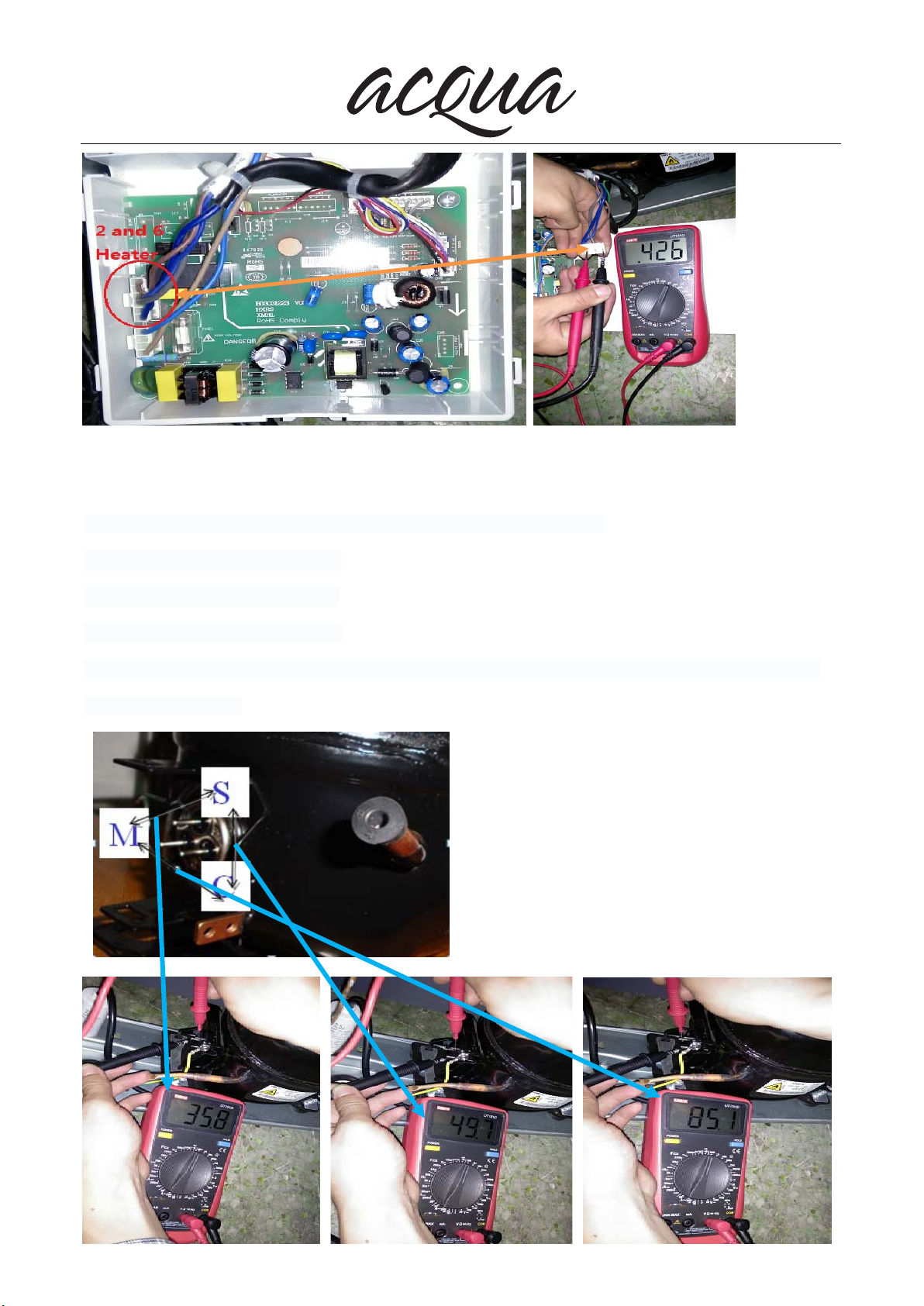
Measuring Temperature fuse and heater resistance
Measuring Temperature fuse and heater resistance,About 426Ω then it is OK.
9
Compressor checking
Use a multi-meter to test the resistance between C & S, M&S and M&C :
Normal range of M&S :About 36Ω
Normal range of C&S : About 50Ω
Normal range of M&C : About 85Ω
If the test result is not in this range then it means the inner coil has some problem and the compressor
can not work properly.

10
Compressor Protector test
Use a multi-meter to test the resistance between the two end as the pic show :
If there show0 0Ωor almost 0Ωthen it is OK.
If there is no response then it is broken.
Compressor PTC starter test
Use a multi-meter to test the resistance between the two end as the pic show :
If there show the number is between About 15Ωthen it is OK.
If there show 000 or no response then it is broken.
11
Compulsory defrost:
Connecting power within 1 minute, refrigerater or freezer door open situation, press Fridge and super
cool 3 seconds, enter the compulsory defrosting process:
——--After entering the compulsory defrosting, we can run the defrosting same as the normal automatic
defrosting process.
——Under compulsory defrosting process, displaying b area displays from 99 to 00.
After exiting the entire compulsory defrosting process, it reverts to normal operation and display.
The guide for Disassembly Common parts of Refrigerator
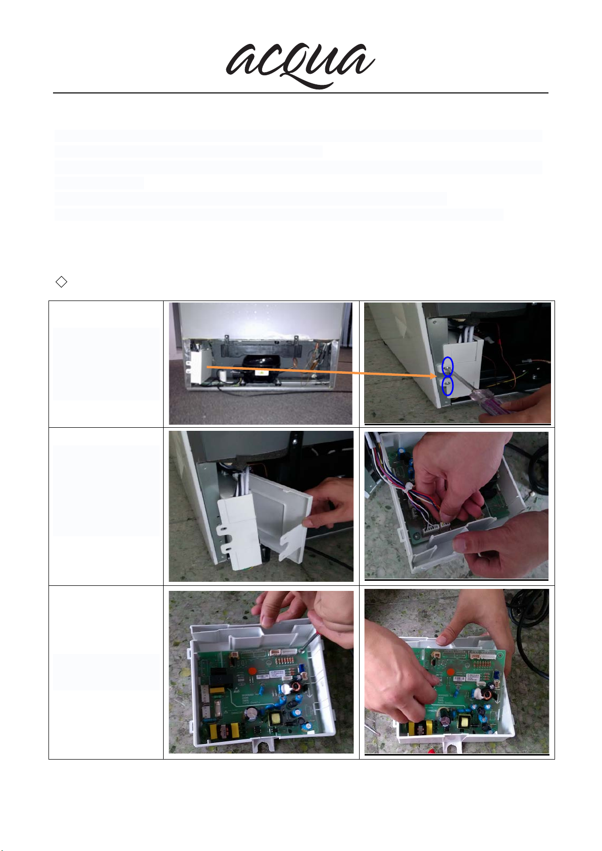
◆The instruction of replacing the main board.
1. The location of the
electrical main board.
2. Unscrew electrical
box ( 2screws ).
3. Remove the
electrical box.
4. Open the electrical
appliances lifted the
lid.
5. Unplug the
electrical wires.
6. Remove the main
board screw

12
7. Take out the main
board.
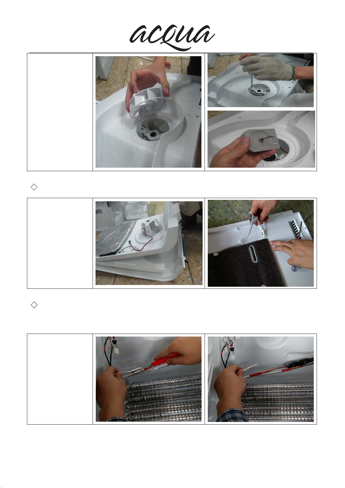
◆The instruction of of replacing fan motor
1.Remove the
refrigerator
compartment
Accessories
2. Remove the air
duct cover screws
3.Remove the air duct
Board
4.Open air duct Board
11
Compulsory defrost:
Connecting power within 1 minute, refrigerater or freezer door open situation, press Fridge and super
cool 3 seconds, enter the compulsory defrosting process:
——--After entering the compulsory defrosting, we can run the defrosting same as the normal automatic
defrosting process.
——Under compulsory defrosting process, displaying b area displays from 99 to 00.
After exiting the entire compulsory defrosting process, it reverts to normal operation and display.
The guide for Disassembly Common parts of Refrigerator
◆The instruction of replacing the main board.
1. The location of the
electrical main board.
2. Unscrew electrical
box ( 2screws ).
3. Remove the
electrical box.
4. Open the electrical
appliances lifted the
lid.
5. Unplug the
electrical wires.
6. Remove the main
board screw
13
5.Unscrew the fan
motor screws
6.Take out fan motor
◆The instruction of replacing temperature sensor.
Open air duct Board
And take out sensor
◆The instruction of replacing evaporator temperature sensor and
temperature fuse and heater.
1.Take out the defrost
sensor.

14
2.Take out the
temperature fuse.
3. Remove
evaporator fixing
screws.
4. Take out the
evaporator.
5.Use a screwdriver
or pliers to pry open
the receiving tank
retaining tabs
6.Take out the water
drain.

15
7.Use pliers to pry
open the heater fixed
buckle.
8. with a craft knife to
cut the Heater cable
fixing bolt.
9.Take out the heater.
◆The instruction of replacing PTC Starting relay and Overload protector.
1. The locat ion of the
PTC Starting relay and
Overload protector.
2. Disconnect the
connecting wire of the
PTC Starting relay and
Overload protector.

16
◆The instruction of replacing Door switch.
Using a screwdriver to
pry the upper cover
plate.
Take out the
magnetron switch.
◆The instruction of replacing Display board.
1. in the display panel
Paste tape( Prevent
scratching shell).

17
2. With a craft knife to
pry open the display
board buckle .
3.Unplug the display
board wires and Take
out display board.
◆The instruction of of replacing LED Light.
1. The locat ion of the
LED Light.
2. Unplug the electrical
wires and remove the
screws fixing the LED
Light board.
Installing your new appliance

18
Troubleshooting
◆The solution for digital display code problem:
1 The digital display window
show “E1”
1. The Refrigerator chamber
Tem. Sensor is open circuit or
short circuit.
2. The Refrigerator chamber
Tem. Sensor is bad.
3. The control PCB is bad.
1. Using a Multimeter with the ohm
switch to measure the resistor of
sensor or checking the connecting is
well or not.
2. Change the sensor
3. Change the control PCB

19
2 The digital display window
show “E2”
1. The Evaporator Defrost
Sensor is open circuit or short
circuit.
2. The Evaporator Defrost
Sensor is bad.
3. The control PCB is bad.
1. Using a Multimeter with the ohm
switch to measure the resistor of
sensor or checking the connecting is
well or not.
2. Change the sensor
3. Change the control PCB
3 The digital display window
show “EC”
1. The receive communication
fault between the main
electrical PCB and the display
PCB.
2. The control PCB is bad.
3. The display PCB is bad.
1. Check the wire terminal is well or
not between the main electrical PCB
and display PCB.
2. Change the main electrical PCB.
3. Change the display PCB.
4 The freezer digital display
window show “EF”
1.The Fan motor is open circuit
or short circuit.
2. The Fan motor is bad.
3. The control PCB is bad.
1. Using a Multimeter with the ohm
switch to measure the resistor of Fan
motor or checking the connecting is
well or not.
2. Change the Fan motor
3. Change the control PCB
The testing method of sensor:
Using the multimeter with the ohm switch to measure the resistor of sensor, normally at surrounding 25℃the
resistor should be about 2kohm and every with the temperature decreases 1℃the corresponding resistor value
would increase about 45ohm.If the measured value is not within the normal scope, the sensor is bad and needs
to repair or change.
◆The common problem judgement method
Problem Cause
Refrigerator can’t start
1.1 Is the power cord connecting well?
1.2 Is the power voltage too low?
1.3 Is the sensor irrational setting?
1.4 Is the ambient temperature too low?
1.5 Is the circuit on power?
1.6 Is there some default in compressor
1.7 Is the refrigeration system blocked by ice or dirty, please stop the unit and restart
after 10 minutes to see if the compressor can start.
Weak cooling effects
2.1 Is there any heat source around the refrigerator?
2.2 Is there enough space around the refrigerator for rejection of heat?
2.3 Is the setting of the temperature appropriate?
2.4 Is there too much food or overheating food in it?
2.5 Does there open the door frequently?
2.6 Is the door completely closed?
2.7 Does the gasket destroyed or distort?
2.8 Does the gas leak?
The unit can not stop
running
3.1 Is there any heat source around the refrigerator?
3.2 Is there enough space around the refrigerator for rejection of heat?
Other manuals for GY-NE42RFW
1
This manual suits for next models
1
Table of contents
Other Acqua Refrigerator manuals

Acqua
Acqua GY-NE350RF User manual

Acqua
Acqua GY-NE242RF User manual

Acqua
Acqua GY-NE255FR User manual

Acqua
Acqua GY-NE350RF/01 User manual

Acqua
Acqua GY-NE42RFS User manual

Acqua
Acqua GY-NE325RFW User manual

Acqua
Acqua GY-NE42RFW User manual

Acqua
Acqua GY-NE250RF User manual

Acqua
Acqua GY-NE272TM User manual

Acqua
Acqua GY-NE250RF User manual


