Acromet WG-602 User manual

WG-602
Water Quality Analyzer
Version 5.13
March 2011

2
1 Preface
1.1 Intended Use
This manual is for qualied and trained service te chnicians who will install and service the WaterGuard
WG-602 Water Quality Analyzer. It provides instruct ions on how to install the WaterGuard system, how to
integrate it with external chemical dosing systems, as well as how to calibrate, operate, and maintain the
system.
Safety Precautions
Warning: Only properly trained and licensed electricians sho uld attempt to wire or service the electronic
components of the analyzer. There is an Electrical Shock Hazard when servicing this system. Always
verify that all electrical power source(s) are o before opening the analyzer unit or attempting to service
electronic components or wiring.
Caution: Extreme caution should be used when installing, op erating, and maintaining the WaterGuard
WG-602 Water Quality Analyzer and Controller. Only properly trained technicians are authorized to install
and maintain the analyzer. Only properly trained and licensed electricians should attempt any change to
the system’s electrical components. Only properly trained and licensed operators should attempt to make
any changes to chemical dosing levels.
Always follow local health and safety regulations when performing any service on the WaterGuard unit or
changing chemical dosing settings.
No part of this publication may be reproduced, trans mitted, trans cribed, s tored in a retrieva l s ys tem,
or trans lated into any language or any computer language, in any fo
rm or by any third party, without
the prior written permis s ion of Acromet (Aust) Pty Ltd.
Disclaimer
Acromet (Aust) Pty Ltd does not accept any responsibiltiy for any damage caused to its products by
unauthorised personnel. Use of non Acromet (Aust) Pty Ltd replacement parts will void all warranties.

3
Table of Contents
1Preface .................................................................................... 2
1.1 Intended Use ........................................................................2
1.2 Overview of Chapters ...........................................................5
2Overview.................................................................................. 5
2.1 Measurements and Features ................................................5
2.1.1 Wireless Management Package .....................................6
2.2 System Components ............................................................6
3Installation................................................................................ 7
3.1 Selecting a Location .............................................................7
3.2 Site Requirements and Installation .......................................7
3.2.1 Mechanical Installation ...................................................7
3.3 Plumbing Requirements and Installation...............................8
3.3.1 Water Supply..................................................................8
3.3.2 Drainage.........................................................................9
3.4 Electrical Requirements and Installation ...............................9
3.4.1 Connecting the Main Electrical Power Source ................9
3.4.2 Input Switches ................................................................9
4First Time Operation and Calibration...................................... 10
4.1 Installing additional Sensors and Meters.............................10
4.2 First Time Menu Setup .......................................................10
4.2.1 WaterGuard Control Panel............................................10
4.2.2 Menus...........................................................................11
4.2.3 Configuring Settings in the Operator Menu...................13
4.3 Calibration ..........................................................................13
4.3.1 Example Calibration - Chlorine .....................................13
4.3.2 Calibrating other Sensors and Meters...........................14
4.4 Technician Menu Setup ......................................................14
4.4.1 Configuring Settings in the Technician Menu................17
4.5 Calibration and Initial Operation Checklist ..........................17
5Routine Operation and Maintenance...................................... 17
5.1 Monitoring WaterGuard Alarms...........................................18
5.2 Shut-Down and Winterizing ................................................18
5.3 Troubleshooting..................................................................19
5.4 Replacing Components ......................................................19
5.4.1 Replacing Flow Switch..................................................20
5.4.2 Replacing Control Panel Module (electronics card) ......20
5.4.3 Replacing I/O Module ...................................................20
5.4.4 Module Software Update ..............................................21

4
Table of Contents
6Additional Features ................................................................ 21
6.1 Cl, pH and Temperature Measurements.............................21
6.1.1 Installation ....................................................................21
6.1.2 Software Set-up............................................................22
6.1.3 Routine Maintenance....................................................23
6.1.4 Shut-down and Winterizing...........................................24
6.1.5 Replacing Sensors........................................................24
6.1.6 Troubleshooting............................................................25
6.2 Turbidity Measurements .....................................................25
6.2.1 Installation ....................................................................25
6.2.2 Relay Wiring and Use ...................................................27
6.2.3 First Time Set-up and General Operation .....................28
6.2.4 Routine Maintenance....................................................29
6.2.5 Cleaning the Turbidity Sensor.......................................29
6.2.6 Shut-down and Winterizing...........................................29
6.2.7 Replacing Components ................................................30
6.3 Conductivity Measurements................................................30
6.3.1 Installation ....................................................................30
6.3.2 First Time Set-up and General Operation .....................31
6.3.3 Routine Maintenance....................................................31
6.3.4 Cleaning the Conductivity Meter ...................................31
6.3.5 Shut-down and Winterizing...........................................31
6.3.6 Replacing Components ................................................32
6.3.7 Replacing the Conductivity Meter .................................32
6.4 Flow Meter..........................................................................32
6.4.1 Installation ....................................................................32
6.4.2 Routine Maintenance and Troubleshooting...................33
6.5 Communication Options......................................................33
6.5.1 External 4 to 20mA Outputs..........................................33
6.5.2 Internal 4 to 20mA Output.............................................36
7Appendix A: Relays and Closed-Loop Control ....................... 38
7.1 Connecting external equipment to the Relays.....................38
7.1.1 Wiring to Dosing Systems.............................................38
7.1.2 Proportional Control Overview ......................................39
7.1.3 Setting Proportional Factor ...........................................40
7.1.4 Setting Pump Period.....................................................40
7.1.5 Step By Step Proportional Settings...............................40
8Appendix B: Technical Specifications..................................... 41

5
1.2 Overview of Chapters
This document is divided into functional sections according to the various steps involved in installing and
operating the WaterGuard system.
Section 1:
Short Overview of manual layout and general
precaution information.
Manual Overview
Section 2:
General description of how WaterGuard automatically
monitors water quality.
Analyzer Overview
Section 3:
Instructions on WaterGuard installation and how to
integrate WG analyzers with water quality systems.
Installation
Section 4:
Instructions to configure, calibrate, and operate the
WaterGuard system immediately after installation.
First Time Set up and Operation
Section 5:
Instructions on responding to alarms and
troubleshooting issues.
Routine Operation and Maintenance
Section 6:
Additional components that may be preinstalled or
upgraded in the field.
Measurement Options
Appendix A:
Description of WaterGuard’s direct control
components and operation.
Relays and Closed Loop Control
Appendix B:
Table summary of technical data for WG-602.
Technical Information
2 Overview
The WaterGuard WG-602 Water Quality Analyzer continuously monitors chemical levels in a process
water application. WaterGuard automates free chlorine, total chlorine, pH, ORP (Redox), temperature,
turbidity, conductivity and/or flow rate, administering chemicals as required, according to the results of
these tests (closed loop).
2.1 Measurements and Features
The WaterGuard unit can be configured to measures any combination of the following water quality
parameters:
•Free Chlorine – Amperometric
•Turbidity
•Conductivity
•pH and Temperature
•Flow Rate
Several communication options are also available:
•Internal 4 to 20 mA Outputs (up to 4 channels)
•External 4 to 20 mA Outputs (up to 8 channels + dry contact alarms)
•HydroSoft - Direct Connection
•Wireless Communication Package*
Optional Module – See supplemental manual for more information

6
2.1.1 Wireless Management Package
An advanced and unique WaterGuard option is the cellular communication package which provides web-
based monitoring of up to 5 analyzers. The cellular communicator accepts WaterGuard's alarms and
readings and transmits them to a web-based application server. The information is easily accessible
remotely through the Internet or mobile telephone.
Caution: Remote control of water chemistry is potentially dangerous; therefore, the WaterGuard remote
monitoring and control service is set by default to monitoring and reporting only.
2.2 System Components
WaterGuard has two primary units: the analyzing unit and the control unit. The analyzing unit performs
the actual measurements and the control units includes all electronics, the user interface and the software
that controls the measurements performed in the analyzing unit. Together, they contain the following
components:
Flow Cell - contains the sensors, including the pH, Redox (ORP), and temperature sensors.
I/O Module (Input/Output) – Power Supply to the analyzer and contains the dry-contact relays for direct
control of external dosing systems.
Control Panel Module – Calculates the measurement results and determines the required chemical
dosing to maintain an appropriate chemical balance in closed-loop systems, and provides data to external
communication devices such as 4 to 20mA Outputs or the wireless communication package.
Keyboard Panel - mounted on the cover of the control module, it functions as WaterGuard’s user
interface. The control panel displays current measurements and indicates alarms. All settings and
adjustments are performed through the control panel.
pH, Redox, Temp Module* – receives the signal from the pH, Redox, and temperature probes.
Internal 4-20 Input Module* - Contains Connections for Turbidity, Conductivity meter, and 4-20 Flow
Meter.
Internal 4 to 20 Output Module* – Provides up to 4, 4 to 20mA outputs for any measured variable.
External 4 to 20 Module* – Provides up to 8, 4 to 20mA outputs for any measured variable. Contains
dry contacts for alarms not related to measured values including: low reagents, no reagents, no flow, etc.
*Optional Module

7
3 Installation
3.1 Selecting a Location
Take extra time in selecting a location since the installation location will determine the ease of the
installation and future operation and maintenance. The location where WaterGuard is installed is
dependent on various considerations:
Convenient Access - WaterGuard should be installed where it can easily be viewed and operated.
Dry Area – WaterGuard handles electricity and includes electronic circuitry that is susceptible to short-
circuiting and/or corrosion when exposed to water or high ambient moisture levels.
Away from Chemicals - Many water treatment chemicals can be corrosive to WaterGuard’s electronic
circuitry. It is highly recommended that WaterGuard is not installed adjacent to the chemicals storage
area or the dosing systems themselves.
Minimum Distance from Supply Pipe - The water sampling line that is connected to the main pipe,
feeding the WaterGuard should be as short as possible. A long sample line from the main pipe to
WaterGuard creates an unnecessary delay between supply, measurement, analysis, and chemical
dosing.
Freezing Temperatures – The analyzer should be installed in a location that is not susceptible to
freezing temperatures. The reagents will freeze, preventing accurate readings (even when thawed) and
parts may be damaged due to expansion when ice forms.
3.2 Site Requirements and Installation
The WaterGuard assembly is wall mounted. It should be located on a wall where operators and service
technicians can easily access it for normal operation and maintenance. It is also advisable to install it
where the operators can easily view the readings and alarms. Finally, the unit weighs approximately 6 lbs.
(3 kg), so, it must be mounted securely onto a stable wall. The WaterGuard unit measures 26.3” x 13.1”
(66.8 cm x 33.2 cm). The base of the complete WaterGuard assembly should be mounted at least 24” (60
cm) above the floor (preferably at eye level).
The WaterGuard unit and its mounting panel are not shipped with mounting screws or anchors. The
installer must provide screws and anchors that can hold the weight of the WaterGuard unit, mounting
panel, intake filter, and electrical outlets and junction boxes. The screws and anchors must be compatible
with the wall where it will be installed.
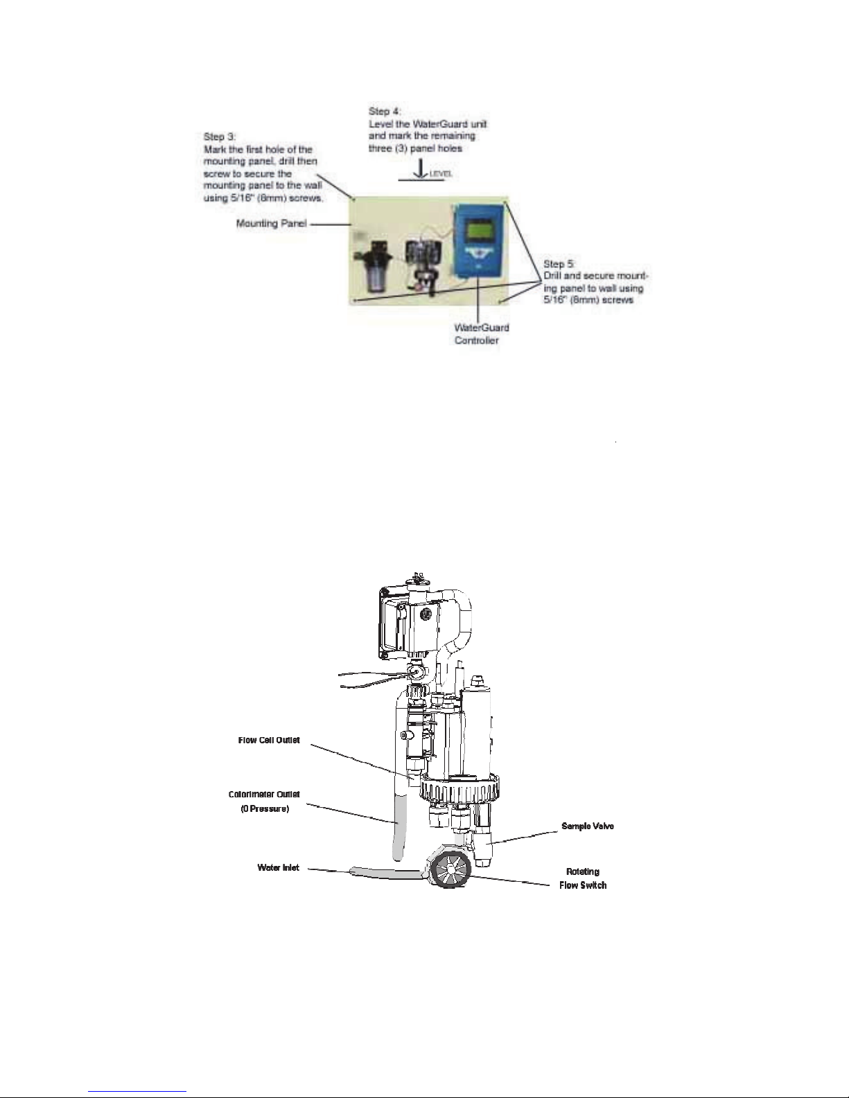
3.2.1 Mechanical Installation
1) WaterGuard is shipped pre-mounted on a mounting panel, along with a water filter. The mounting
panel includes four screw holes, one in each corner.
2) Determine the location of one hole on the WaterGuard unit or on the mounting panel.
3) Secure one corner of the WaterGuard unit or mounting panel to the wall.
4) Level the WaterGuard unit or mounting panel and mark the remaining three (3) screw holes.
5) Secure the remaining corners to the wall using 5/16” (8 mm) screws.
Figure
3.3
Plumbing Requirements and Installation
3.3.1 Water Supply
WaterGuard requires a pressurized water supply to t
from the colorimeter and a pressurized (or gravity)
installed in the main line and the pipe (or tube) f
to minimize the delay time between the water being
adjustiQJ GRVLQJ OHYHOV
VHH VHFWLRQ
should be adjusted to 7 psi (0.5 bar) using a press
Figure
2
8
Figure
1: WaterGuard 602 Mounting Panel
Plumbing Requirements and Installation
WaterGuard requires a pressurized water supply to the flow cell, a zero pressure (gravity) water retur
from the colorimeter and a pressurized (or gravity) return from
the flow cell. An isolating valve must be
installed in the main line and the pipe (or tube) from the main pipe should be as short as possible, i
to minimize the delay time between the water being sampled and WaterGuard testing the water and
VHH VHFWLRQ
3.1). The inlet pressure should not exceed 36 psi (
should be adjusted to 7 psi (0.5 bar) using a pressure regulator attached to the outlet of the pre
2
: Flow cell and Colorimeter Inlet and Outlet
he flow cell, a zero pressure (gravity) water return
the flow cell. An isolating valve must be
rom the main pipe should be as short as possible, in order
sampled and WaterGuard testing the water and
3.1). The inlet pressure should not exceed 36 psi (2.5 bar) and
ure regulator attached to the outlet of the pre
-filter.

9
3.3.2 Drainage
A pressurized, vacuum, or gravity connection is required from the outlet of the flow cell. The flow cell may
be pressurized up to 7 psi (0.5 bar) and a ¼” FNPT fitting is supplied for the flow cell drain connection.
3.4 Electrical Requirements and Installation
WaterGuard requires a 90-120 or 180-240 VAC, 50/60 Hz electrical power source on a separate 16A
circuit in the plant room’s electrical board. The main WaterGuard power supply should be connected to a
non-dependent power supply, so that the unit remains powered constantly. The active relays should be
connected to a (pump) dependent power supply (interlocked power supply) to provide an additional layer
of prevention against chemical addition and equipment operation when the main water supply is not
operating.
3.4.1 Connecting the Main Electrical Power Source
The Main Power Supply may be connected to either 90-120 or 180-240VAC 50/60Hz. Switching between
voltages is accomplished by changing two (2) jumpers located above the main power connection, to the
left of the transformer. For 90-120VAC, a 1amp fuse should be use; for 180-240VAC, a 0.5amp fuse
should be used. These changes must be completed prior to wiring.
Caution: Before making a connection to a power source, confirm that both jumpers are located on the
correct voltage and that the appropriate fuse is in place.
6) Verify that the power switch or circuit breaker to the non-dependent power source is off.
7) Connect the line (live) wire to the I/O board connector marked Line.
8) Connect the neutral wire to the I/O board connector marked Neutral.
9) Connect the earth wire to the I/O Module connector marked Ground.
10) Continue with the other electrical connections.
11) Turn on electrical power only after all electrical connections have been completed.
For information on wiring and using the relays as dry contact or for control, see Appendix A.
3.4.2 Input Switches
Flow input switch terminal blocks on the I/O module allow for three input switches to be connected to the
system as additional layers of security against accidental chemical additions when there is no flow. If a
connection is expected but not detected at each input, the analyzer/controller will indicate an alarm and
will close all relays (and open the alarm relay). Therefore, if a safety switch (flow, level, etc.) will not be
installed, a fixed connection (jumper wire) is required to allow the controller to operate.
Two flow switches and one flow meter may be connected:
•Flow Switch (internal): Flow switch connected to flow cell of analyzer. Supports both 2 and 3 wire
flow switches.
oIf a 2 wire switch is used, it should be connected to the “In” and “Gnd” connections. If a 3
wire switch is used, the “VCC” connection will also be used.
oIf a rotating flow switch is used, the J25 jumper should be in place; if a float-type or other
on/off flow switch is used, the J25 jumper should be removed (to be used with the open
cell analyzer models).
•External Flow Switch: Connection for external 2-wire flow switch. If an external switch is not
connected, a jumper must be installed for the analyzer to operate properly.

10
•Flow Meter: Connection for 2 or 3 wire flow Meter. The analyzer will not look for the flow meter
connection unless the option is turned ON in technician menu; therefore, no jumper is required if
a meter is not installed.
Caution: Electrical connections in this section are ONLY recommendations. All electrical
connections should comply with National Electrical code (NEC) and all local regulations.
First Time Operation and Calibration
3.5 Installing additional Sensors and Meters
Install all additional sensors and meters and connect to the WG-602 main system, following the
supplemental manuals for each sensor or meter.
3.6 First Time Menu Setup
This section describes how to configure the settings (set points, alarms, and calibrations) through the
WaterGuard control panel.
Caution: WaterGuard's control board unit should not be opened except for initial installation and
troubleshooting and should only be opened by a trained and approved technician.
3.6.1 WaterGuard Control Panel
The WaterGuard control panel is a simple, intuitive interface for monitoring and controlling water quality
with the following components:
When an alarm is issued, the bottom row of the LCD displays the alarm.
Pressing the up and down arrows together will display the Langelier index for approximately five (5)
seconds, and then returns to the previous display mode.
3.6.2 Menus
WaterGuard has two menu levels: Operator and Technician. The Operator menu includes settings that
may be controlled by on-site operators. The Technician menu includes settings and calibrations that
should be restricted to specially trained WaterGuard maintenance technicians. Each menu has a
separate password. The technician level password may be used whenever a password is required,
however the operator password will only be accepted in the operator menu.
Table 1 displays the operator menu functions and their description and Table 2 displays the menu
functions with the minimum and maximum values for each.

11
Table 1: Operator Menu Functions and Descriptions
0(18 1$0( '(6&5,37,21
6KRFN&O
7XUQ&O
6KRFN2Q2II
0HQX5HOD\V 0DQXDODF LYD LRQRI5HOD\V
&O
6H SRLQ &RQ UROV&O
5HOD\2Q2IIRU3URSRU LRQDO
&O
6KRFN6H SRLQ 6H SRLQ IRU&O6KRFN
&O
6H SRLQ &RQ UROV&O
5HOD\2Q2II2QO\
&O
&DOLEUD HG7R
6KRZVPRV UHFHQ FDOLEUD LRQDQG
VHQVRUYDOXH
D FDOLEUD LRQ RDLGLQ URXEOHVKRR LQJ
&O
6HQVRU:DV
&O
/RZ$ODUP $ODUPZKHQ&O
EHORZ KLVYDOXH
&O
+LJK$ODUP $ODUPZKHQ&O
DERYH KLVYDOXH
S+6H SRLQ &RQ UROVS+5HOD\ 2Q2IIRU3URSRU LRQDO
S+&DOLEUD HG7R 6KRZVPRV UHFHQ FDOLEUD LRQ RDLGLQ URXEOHVKRR LQJ
S+6HQVRU:DV
6KRZVVHQVRUYDOXHD FDOLEUD LRQ RDLGLQ
URXEOHVKRR LQJ
S+/RZ$ODUP $ODUPZKHQS+EHORZ KLVYDOXH
S++LJK$ODUP $ODUPZKHQS+DERYH KLVYDOXH
7HPS6H SRLQ &RQ UROV7HPSHUD XUH5HOD\
7HPS&DOLEUD HG7R 6KRZVPRV UHFHQ FDOLEUD LRQDQG
VHQVRUYDOXHD FDOLEUD LRQ RDLGLQ URXEOHVKRR LQJ
7HPS6HQVRU:DV
7HPS/RZ$ODUP $ODUPZKHQ HPSEHORZ KLVYDOXH
7HPS+LJK$ODUP $ODUPZKHQ7HPSDERYH KLVYDOXH
7XUELGL \6H SRLQ &RQ UROV7XUELGL \5HOD\RS LRQDOPRGXOH
178/&DOLEUD HG7R 6KRZVPRV UHFHQ 178ORZFDOLEUD LRQDQG
VHQVRUYDOXHD FDOLEUD LRQ RDLGLQ URXEOHVKRR LQJ
6HQVRU9DOXH:DV
178+&DOLEUD HG7R 6KRZVPRV UHFHQ 178KLJKFDOLEUD LRQDQG
VHQVRUYDOXHD FDOLEUD LRQ RDLGLQ URXEOHVKRR LQJ
6HQVRU9DOXH:DV
7XUE+LJK$ODUP
$ODUPZKHQ7XUELGL \DERYH KLVYDOXHRS LRQDO
PRGXOH
&RQGXF LYL \
&DOLEUD HG7R 6KRZVPRV UHFHQ &RQGXF LYL \FDOLEUD LRQDQG
VHQVRUYDOXHD FDOLEUD LRQ
6HQVRU9DOXH:DV
$ODUP'HOD\ 7LPHGHOD\EHIRUH$ODUP5HOD\FORVHV
)ORZ/RZ/LPL /RZIORZOLPL IRUH[ HUQDOIORZPH HU
)ORZ.)DF RU .)DF RUIRUH[ HUQDOIORZPH HU
7R DO$ONDOLQL \ 0DQXDOO\HQ HUHGIRU/DQJHOLHU,QGH[
7R DO+DUGQHVV 0DQXDOO\HQ HUHGIRU/DQJHOLHU,QGH[
7'6 0DQXDOO\HQ HUHGIRU/DQJHOLHU,QGH[
/DQJXDJH $OORZVFKRLFHRIODQJXDJH
6\V HP5HVH 5HV DU VFRQ UROOHUVDIHU KDQ XUQLQJRIIDQGRQ

12
Table 2: Operator Menu and Variable Limits
0(18
1$0(
0,1,080
9$/8(
0$;,080
9$/8(
'()$8/7
81,76
6KRFN&O
2)) 21 2)) ȸ
0HQX5HOD\V
2))
21
2))
ȸ
&O
6H 3RLQ 330
&O
6KRFN6H 3RLQ 330
&O
6H 3RLQ 330
&O
&DOLEUD HG7R
1$
330
&O
6HQVRU:DV 1$ 330
&O
/RZ$ODUP 330
&O
+LJK$ODUP 330
S+6H 3RLQ
ȸ
S+&DOLEUD HG7R
1$
ȸ
S+6HQVRU:DV
1$
ȸ
S+/RZ$ODUP
ȸ
S++LJK$ODUP
ȸ
7HPS6H 3RLQ
ͼ
&
ͼ
&RU
ͼ
)
7HPS&DOLEUD HG7R
1$
ͼ
&RU
ͼ
)
7HPS6HQVRU:DV
1$
ͼ
&RU
ͼ
)
7HPS/RZ$ODUP
ͼ
&
ͼ
&RU
ͼ
)
7HPS+LJK$ODUP
ͼ
&
ͼ
&RU
ͼ
)
7XUELGL \6H SRLQ
178
178/&DOLEUD HG7R
1$
178
6HQVRU9DOXH:DV
1$
178
178+&DOLEUD HG7R
1$
178
6HQVRU9DOXH:DV
1$
178
7XUE+LJK$ODUP
178
&RQGXF LYL \
&DOLEUD HG7R
1$ 86
6HQVRU9DOXH:DV
1$
P
KURU
*30
$ODUP'HOD\
0LQX HV
)ORZ/RZ/LPL
RU
2))
P
KURU
*30
)ORZ.)DF RU
ȸ
7R DO$ONDOLQL \
330
7R DO+DUGQHVV
330
7'6
330
/DQJXDJH
(QJOLVK
ȸ
6\V HP5HVH
1$
1$
1$
ȸ
/DQJXDJH6HOHF LRQ

13
3.6.3 Configuring Settings in the Operator Menu
Each of the parameters in the operator menu is configured in the same way. The following procedure
describes how to configure a typical setting:
12) Locate the desired parameter in the menu:
a) Press Menu until the desired parameter name appears in the LCD display.
13) Press OK. Enter Password 100 appears in the LCD display.
14) Enter the Operator password (or technician password; both are accepted)
15) Press the up arrow or down arrow until the password number is reached.
Note: Holding Menu why pressing up or down will advance the first digit. Holding up or down for an
extended period of time will proceed through the numbers more quickly.
The factory-set operator password is 123. The operator password can only be changed by entering
the current operator or technician password (see Technician Menu Setup).
16) Press Enter to accept the password. The parameter name and current setting appear in the LCD
display.
17) Press Enter, again. The LCD display shows the parameter and the current setting.
18) Enter the new parameter setting:
a) Press the up arrow or down arrow until the desired value is reached.
b) The second row of the menu display, below the value that is being changed, shows the current
value.
19) Press Enter to save the new setting or Esc to abort without saving the new setting.
To change the settings of additional parameters, press Menu until the desired parameter appears in the
LCD display and repeat steps 6-8 above to set the new parameter.
Note: The Menu button displays the next parameter in the list, so that the operator can check every
parameter in the menu. There is no scroll-back option. To view or change a previous parameter in the
menu, you must exit the menu by pressing Esc, and start the above procedure from the beginning.
3.7 Calibration
Parameters must be calibrated with measurements taken with external testing devices. Always use digital
calibration devices, not the less accurate visual test kits. Alternatively, standard solutions may be used.
Make sure the standard solution is not expired or contaminated prior to using. Follow the procedures
below EXACTLY as instructed.
ALWAYS take water for calibration from the sampling valve, NOT from the process line directly. The
analyzer should always be calibrated with water from the same source.
Following calibration directions for each sensor as indicated in the sensor manual; however chlorine is
listed below as an example.
3.7.1 Example Calibration - Chlorine
20) Open the water sampling valve.
21) Fill the sampling container.
22) Test the water sample for chlorine using a digital photometer.
23) Press Menu until “Cl Calibrated to” appears in the LCD display.

14
The top line will display “Cl Calibrated to” and a number. The number displayed is the last value
someone entered for the calibration. The bottom line will display “Cl Sensor was” and a number. This
number is the sensor reading without any calibration at the time of the last calibration. If there is a large
discrepancy between these two numbers, the sensor was calibrated improperly or there is a problem with
the analyzer. The value displayed normally on the main screen and the value the analyzer uses to
determine dosing rates is the calibrated value.
24) Press OK.
25) Enter the password. Press the up arrow or down arrow until the password is reached.
26) Press OK.
27) Press OK again.
The display will now show “Calibrate Cl to” on the top line and “Sensor Reading” on the bottom line. The
“Sensor Reading” is the current reading of the sensor with no calibration. The “Calibrate Cl to” value is
the new value which you want to set.
28) Press the up arrow or down arrow until the value is the same as the value given by the digital
photometer.
29) Press OK to save the new calibration or Esc to abort without saving.
30) Press Esc to return to the main display.
3.7.2 Calibrating other Sensors and Meters
Calibration of other sensors and meters is similar to the chlorine calibration and requires the use of a
reliable external testing device or standard solution. See the supplemental manuals for each sensor or
meter for specific information on calibration.
3.8 Technician Menu Setup
The Technician menu includes advanced parameter settings that are accessible separately from the
Operator menu. Anyone can view the settings, but only someone with technician password can change.
This has been done to allow only those who are qualified to change the advanced analyzer settings.
These are also settings that should not require frequent changes after the initial installation and set-up.

15
Table 3: Technician Menu Functions and Descriptions
0(18
1$0(
'(6&5,37,21
&O
3)DF RU
3URSRU LRQDO)DF RUIRU&O
5HOD\
&O
3XPS3HULRG
3XPSF\FOH2Q2II LPHIRU&O
5HOD\
&O
3XPS)UHTXHQF\
&O
SXPSPD[SXOVHVPLQIRU2Q2II
&O
$YHUDJLQJ
'LVSOD\VDQDYHUDJHRI KHODV &O
UHDGLQJV
&O
6HQVRU7\SH
6HOHF ZKLFK&O
6HQVRULVFRQQHF HG
S+S)DF RU
3URSRU LRQDO)DF RUIRUS+5HOD\
S+3XPS3HULRG
3XPSF\FOH2Q2II LPHIRUS+5HOD\
S+3XPS)UHT
S+SXPSPD[LPXPSXOVHVPLQIRU2Q2II
SK%DODQFH7\SH
7RVHOHF LIDFLGRUEDVHLVEHLQJDGGHG R
)ORZ6HQVRU
:LOO XUQGLVSOD\RI)ORZUD HRQRII2QO\XVH
)ORZ5D H
&KRRVHEH ZHHQPH ULFDQG(QJOLVKXQL V
&HOVLXV)DUK
&KRRVHEH ZHHQPH ULFDQG(QJOLVK
7HPS+\V HUHVLV
9DOXHLQGHJUHHVEHORZVH SRLQ ZKLFKZLOO
7XUELGL \
7XUQV7XUELGL \PRGXOH212))RS LRQDO
178:LSHU,Q HUYDO
,Q HUYDOIRU7XUELGL \PRGXOH:LSHU RFOHDQ
0LQX HV
&XUUHQ LPHIRUGD DORJJHU
+RXU
&XUUHQ LPHIRUGD DORJJHU
'D\
&XUUHQ LPHIRUGD DORJJHU
0RQ K
&XUUHQ LPHIRUGD DORJJHU
<HDU
&XUUHQ LPHIRUGD DORJJHU
5HFRUGLQJ,Q HUYDO
7LPHLQ HUYDOEH ZHHQUHDGLQJVV RUHGRQ KH
9LHZ)UHH&O
'LVSOD\VPHDVXUHPHQ YDOXHRQ/&'
9LHZS+
'LVSOD\VPHDVXUHPHQ YDOXHRQ/&'
9LHZ&RQGXF LYL \
'LVSOD\VPHDVXUHPHQ YDOXHRQ/&'
$GGUHVV
&RQ UROOHU,'XVHGZL KH[ HUQDO
6RI ZDUH9HUVLRQ
&XUUHQ VRI ZDUHYHUVLRQ
0D[)ORZ5DQJH
0D[LPXP)ORZ5D HIORZD $RI
$2X SX 6H LQJV
&RQILJXUHVRX SX VIRULQ HUQDO$
2Q$ODUP*R7R
$RX SX GXULQJDQDODUPFRQGL LRQ
2SHUD RU3DVVZRUG
&KDQJHRSHUD RUSDVVZRUG
7HFKQLFDO3DVVZRUG
&KDQJH HFQLFKDOSDVVZRUG

16
Table 4: Technician Menu and Variable Limits
0(18
1$0(
0,1,0809$/8(
0$;,080
9$/8(
'()$8/7
81,76
&O
3)DF RU ȸ
&O
3XPS3HULRG 0LQX HV
&O
3XPS
)UHTXHQF\
212))
SXPS
0D[LPXP
SXOVHVPLQ
&O
$YHUDJLQJ 2)) 21 21 ȸ
&O
6HQVRU7\SH ȸ
S+S)DF RU
ȸ
S+3XPS3HULRG
0LQX HV
S+3XPS)UHT
212))
0D[LPXP
SK%DODQFH7\SH
$FLG
%DVH
$FLG
ȸ
)ORZ6HQVRU
2))
21
2))
ȸ
)ORZ5D H
P
KU
*30
P
KU
ȸ
&HOVLXV)DUK
ͼ
&
ͼ
)
ͼ
&
ȸ
7HPS+\V HUHVLV
ͼ
&RU
ͼ
)
7XUELGL \
2))
21
2))
ȸ
178:LSHU,Q HUYDO
0LQX HV
0LQX HV
1$
0LQX HV
+RXU
1$
+RXUV
'D\
1$
'D\V
0RQ K
1$
0RQ KV
<HDU
1$
<HDUV
5HFRUGLQJ,Q HUYDO
0LQX HV
9LHZ)UHH&O
2)) 21 21 ȸ
9LHZS+
2))
21
21
ȸ
9LHZ&RQGXF LYL \
2))
21
21
ȸ
$GGUHVV
ȸ
6RI ZDUH9HUVLRQ
1$
1$
1$
ȸ
0D[)ORZ5DQJH
P
KU
RU*30
$2X SX
6H LQJV
1$ 1$ 1$ ȸ
2Q$ODUP*R7R
1$
2SHUD RU
3DVVZRUG
ȸ
7HFKQLFDO
3DVVZRUG ȸ

17
3.8.1 Configuring Settings in the Technician Menu
Navigation within in the Technician Menu is identical to the operator menu.
1) To enter the Technician menu, press Menu to enter the operator menu and then the up arrow and
down arrow together simultaneously until the menu display changes.
2) Locate the desired parameter in the menu:
a) Press Menu until the desired parameter name appears in the LCD display.
b) Press OK. Enter Password 100 appears in the LCD display.
3) Enter the Technician menu password:
a) Press the up arrow or down arrow until the password number is reached.
b) Press OK. The parameter name and current setting appear in the LCD display.
Note: Technician menu password is different from the Operator menu password. The default
Technician menu password is 456 and if lost, can only be reset by replacing the chipset.
4) Continue changing the parameter setting, as described in the Operator menu.
3.9 Calibration and Initial Operation Checklist
Before leaving the site, perform the procedure in this section and record the requested values.
Calibrate the following WaterGuard parameters and enter the information into the table below. If pH is
reading slightly low, do not calibrate as it will continue to increase for the first 24-48 hours.
4 Routine Operation and Maintenance
Once installed by a qualified technician, WaterGuard can begin monitoring and controlling water quality.
WaterGuard is specifically designed for easy operation; however some periodic maintenance is still
required.
•Basic Operation: involves setting the desired parameters and monitoring the system for alarms.
When operating normally, WaterGuard demands very little operator involvement.
•Calibration: Sensor sensitivity and accuracy can degrade or drift over time. For this reason,
WaterGuard settings must be periodically recalibrated and compared with measurements from
other measuring devices, such as electronic photometers, pH sensors, and thermometers or
compared to standard solutions like pH buffers.
18
•Shut-down and Winterizing: If the analyzer will not be operating for an extended period of time
or in areas where temperatures drop below freezing, all water must be removed from the analyzer
to prevent components from breaking and the probes must be removed and stored in a warm
area and kept wet at all times.
•Troubleshooting: Occasionally problems will occur with the analyzer readings or chemical
dosing. These problems are most often simple to correct. The troubleshooting section provides
an outline to follow to help correct the problems easily.
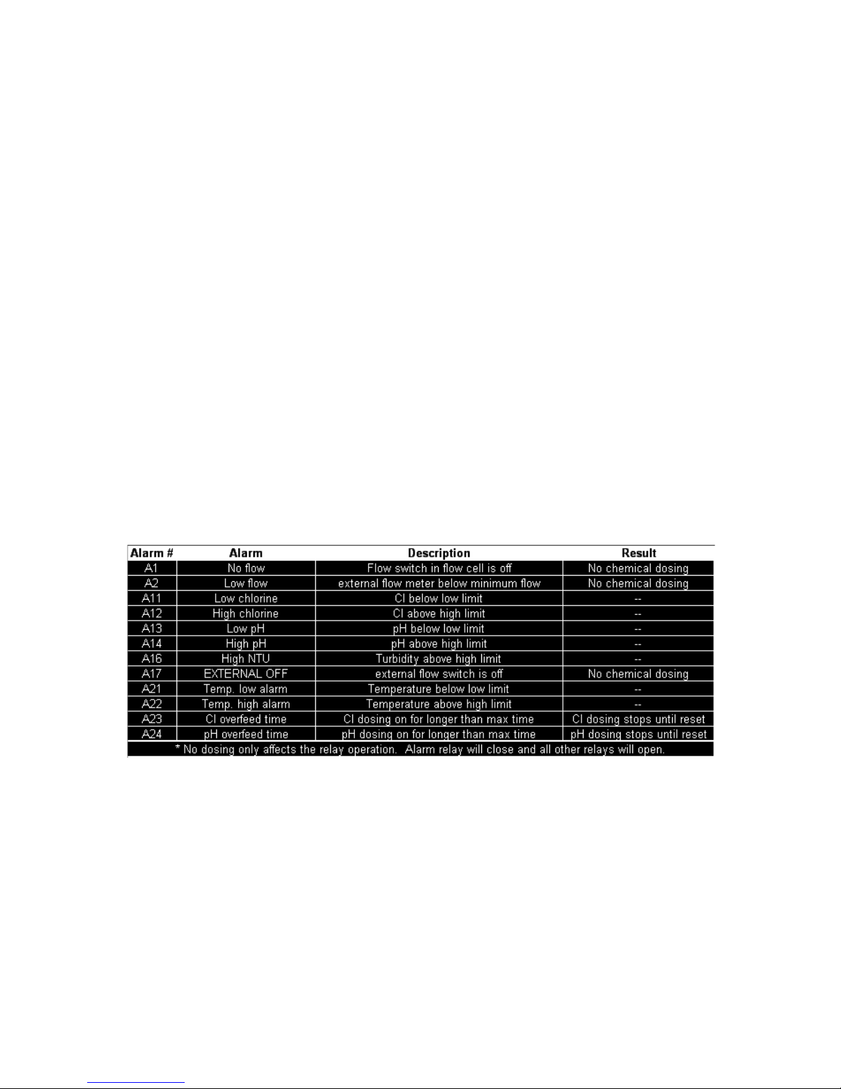
4.1 Monitoring WaterGuard Alarms
WaterGuard issues alarms when it detects chemical levels that are above or below the allowed range.
Every alarm is automatically displayed in the LCD status display and logged in the data logger. Most
deviations in chemical levels, however, are automatically corrected. Thus, the internal alarms do not
immediately activate an external alarm. A delay mechanism prevents false alarms from minor deviations
that were automatically corrected. The external alarm is only activated after an internal alarm has been
continuously active for a certain period of time, as defined by the operator.
The Alarm Delay command in the Operator menu sets the number of seconds WaterGuard waits before
closing Relay 5, the relay that operates the external alarm. Only one alarm is shown on the screen at a
time based on importance and the order in which it should be fixed. For example, if the pH is high and
the ORP is low, only the pH alarm will be indicated since lowering the pH will likely also correct the low
ORP. All of the alarms are presented in Table 5 along with a description and resulting action of the
analyzer/controller.
Table 5: Alarm Description and Result
4.2 Shut-Down and Winterizing
The WaterGuard analyzer is designed to keep the probes submerged even if there is no flow to the
analyzer. However, if the analyzer is going to be offline for an extended period of time and/or exposed to
freezing temperatures, it must be winterized to prevent damage to the analyzer and the probes.
1) Store all probes following directions in the supplemental manuals for each sensor.
2) Drain the flow cell completely by opening the sampling valve on the bottom. Leave the valve in the
open position to allow air to completely dry the cell.
3) Check the security of the analyzer doors to ensure a weatherproof seal.

19
4.3 Troubleshooting
The following procedures instruct how to locate, evaluate, and fix a problem when WaterGuard issues an
alarm or indicates suspect chemical levels.
4.4 Replacing Components
The following procedures describe how to replace certain WaterGuard components.
Caution: The following procedures should only be performed by properly qualified and trained
WaterGuard analyzer technicians.
Warning: Disconnect all power supplies to the WaterGuard analyzer before opening the control unit door.
Replacing any parts of WaterGuard without the expressed written authorization of Chemical Injection
Technologies, Inc., or the qualified representative who supplied the product may void the warranty.
Chemical Injection Technologies, Inc., takes no responsibility, written or implied, for installation or
maintenance of WaterGuard that is not performed by a properly trained and certified WaterGuard
technician.

4.4.1
Replacing Flow Switch
1)
Turn off the inlet and outlet water to the flow cel
2)
Open the doors of both the analyzing
3)
Locate the flow switch attached to the flow cell.
4)
Disconnect the flow switch wires from the I/O modul
5)
Remove the inlet connection to the old flow switch.
6)
Remove the flow switch from the flow cell.
7) Pull the flow switch wires
gently to completely remove from the analyzer
8)
Insert the new flow switch on the flow cell
9)
Insert the inlet connection on the flow switch
10)
Route the flow switch wires back to the connection
input switch terminal block.
11)
Close the analyzer doors and turn on the water and
4.4.2
Replacing Control Panel Module (electronics card)
Disconnect the power supply to the unit before open
1)
Disconnect the flat cable plug fr
2)
Unscrew the four (4) mounting screws.
3)
Put in the new card and tighten the 4 mounting scre
4)
Connect the flat cable plug to the card.
Figure 3:
Replacing all types of electronic modules (cards)
4.4.3 Replacing I/O
Module
Disconnect the power supply to the unit before open
1)
Disconnect the flat cable plug from the card.
2)
Unscrew the four (4) mounting screws.
3)
Put in the new card and tighten the 4 mounting scre
4)
Connect the flat cable plug to the
20
Replacing Flow Switch
Turn off the inlet and outlet water to the flow cell and the power to the analyzer.
Open the doors of both the analyzing
module and the control module.
Locate the flow switch attached to the flow cell.
Disconnect the flow switch wires from the I/O module.
Remove the inlet connection to the old flow switch.
Remove the flow switch from the flow cell.
gently to completely remove from the analyzer
Insert the new flow switch on the flow cell
Insert the inlet connection on the flow switch
Route the flow switch wires back to the connection on the I/O module and connect the wires to the
Close the analyzer doors and turn on the water and power and ensure proper operation.
Replacing Control Panel Module (electronics card)
Disconnect the power supply to the unit before opening the control unit.
Disconnect the flat cable plug fr
om the card.
Unscrew the four (4) mounting screws.
Put in the new card and tighten the 4 mounting screws.
Connect the flat cable plug to the card.
Replacing all types of electronic modules (cards)
Module
Disconnect the power supply to the unit before opening the control unit.
Disconnect the flat cable plug from the card.
Unscrew the four (4) mounting screws.
Put in the new card and tighten the 4 mounting screws.
Connect the flat cable plug to the
card.
on the I/O module and connect the wires to the
power and ensure proper operation.
Table of contents
Popular Measuring Instrument manuals by other brands


Valeport
Valeport fastCTD operating manual

Dwyer Instruments
Dwyer Instruments MFS2-3 Installation and operating instructions

Circutor
Circutor CEM-C12 instruction manual

Zoom
Zoom H4N quick start guide

NUCLEONIX SYSTEMS PRIVATE LIMITED
NUCLEONIX SYSTEMS PRIVATE LIMITED GR612 instruction manual

FRC
FRC DFA400 instruction manual