ACSI FORCE AIR 700 Installation and operation manual

8720 LAMBRIGHT ROAD
HOUSTON, TEXAS 77075
PHONE: (713) 987-0336, FAX: (713) 987-0355
www.acsi-us.com
FORCED AIR 700 PORTABLE HEPA FILTRATION UNIT
PART ORDER NUMBER: FA700
OPERATING & MAINTENANCE MANUAL
DOCUMENT NUMBER: OPMM-002E-R0

DOCUMENT NUMBER: OPMM-002E-R0
Proprietary Information: This document is the property of ADVANCED CONTAINMENT SYSTEMS, Inc. It shall not be copied
or duplicated and shall not be submitted to outside parties without the company consent.
Page 2 of 8 10/5/2016
RELEASES:
1. Original Release: January 11, 2005, revision 1
NOTE:
1. The purpose of this document is to provide the basic operation and maintenance information for the
FORCED AIR 700 PORTABLE HEPA FILTRATION UNIT.
2. This manual is limited to items stated within. Any changes, additions or modifications will require a
document amendment approved by ADVANCED CONTAINMENT SYSTEMS, Inc.
REFERENCE DOCUMENTS:
1. Drawing Num. FA700-ES-R0: Electrical Schematic
2. Drawing Num. FA700-LD-R0: Ladder Diagram
INDEX:
1. GENERAL INFORMATION
2. DIMENSIONS
3. OPERATION
4. FILTRATION
5. FILTERS REPLACEMENT
6. ELECTRICAL SCHEMATIC
7. LADDER DIAGRAM
8. REPLACEMENT PARTS LIST
NOTE:
ALL UNITS MANUFACTURED BY ADVANCED CONTAINMENT SYSTEMS INC.
(ACSI) MEET ALL STANDARDS REQUIREMENTS SET BY THE AMERICAN
NATIONAL STANDARS INSTITUTE (ANSI) Z2.9, AND ARE OSHA APPROVED.
ELECTRICAL COMPONENTS ARE “UL” LISTED AND “CSA” CERTIFIED.
DOCUMENT NUMBER: OPMM-002E-R0
Proprietary Information: This document is the property of ADVANCED CONTAINMENT SYSTEMS, Inc. It shall not be copied
or duplicated and shall not be submitted to outside parties without the company consent.
Page 3 of 8 10/5/2016
1. GENERAL INFORMATION:
1.1 The FORCED AIR 700 PORTABLE HEPA FILTRATION UNIT is designed for indoor use and
to provide the most efficient air filtration with three stages of filtration. One stage with HEPA
(High Efficiency Particulate Air) filtration, that can remove 99.97% of particles 0.3 micron or
larger from the air stream.
2. DIMENSIONS:
2.1 Length: 33”
2.2 Width: 18”
2.3 Height: 18”
2.4 Weight: 67 lb
2.5 Housing: 0.063 Aluminum
2.6 Air Flow (High Speed): 700 cfm
2.7 Air Flow (Low Speed): 400 cfm
2.8 Motor: 0.25 HP, Variable Speed
2.9 Power Supply: 115 VAC, 60 Hz, 3.3 amp
3. OPERATION:
3.1 Electrical Requirements:
3.1.1 The FA700 requires a minimum of 115 VAC, 60 Hz, 3.3 amp, power supply for
normal operation.
3.1.2 The unit requires a heavy duty industrial grade 12-3 cord, in good condition, and
should not exceed 50 ft. in continuous length to operate properly. If more than 50 ft is
needed, please consult with your distributor.
3.1.3 The unit needs to be grounded properly, including the ground pin on the plug. Keep
electrical cords away from water or do not use any damaged cord.
3.2 Unit Set-up:
3.2.1 The unit should be located away from doorways or other make-up air sources.
3.2.2 Place the end of the exhaust port through an opening in the plastic barrier or wall
covering, using duct tape to seal off any opening. Do not exhaust to uncontaminated
or occupied areas.
CAUTION
DO NOT OPERATE THE FA700 WITHOUT THE HEPA FITLER INSTALLED!
OPERATING WITHOUT THE HEPA FILTER INSTALLED OR USING NON-APPROVED
POWER CORDS MAY CAUSE DAMAGE TO THE ELECTRICAL SYSTEM OR
MECHANICAL COMPONENTS. FAILURE TO COMPLY WILL VOID ALL WARRANTIES.

DOCUMENT NUMBER: OPMM-002E-R0
Proprietary Information: This document is the property of ADVANCED CONTAINMENT SYSTEMS, Inc. It shall not be copied
or duplicated and shall not be submitted to outside parties without the company consent.
Page 4 of 8 10/5/2016
Fig. 1 Control Panel
3.3 Control Panel:
3.3.1 Variable Speed Switch to start and select the speed of the unit
3.3.2 Push Button Breaker 15 Amp
3.3.3 Power Supply Receptacle
3.3.4 Pressure Gauge
3.3.5 Sensing Port
3.4 Turning Unit On:
3.4.1 The switch must be in off position, before connecting the power supply.
3.4.2 Connect the power supply.
3.4.3 To start the unit, the main switch is located on the control panel (see fig. 1) and is a
variable speed switch. Turn the switch to the desire speed.
3.5 Turning Unit Off:
3.5.1 To turn the unit off, set the switch in the off position.
3.5.2 At the end of the project, the filters should not be removed, instead the intake
opening should be sealed with polyethylene and duct film tape.
Vari-Speed Switch
Breaker 15 Amp
Pressure Gauge
PS Receptacle
Sensing Port
DOCUMENT NUMBER: OPMM-002E-R0
Proprietary Information: This document is the property of ADVANCED CONTAINMENT SYSTEMS, Inc. It shall not be copied
or duplicated and shall not be submitted to outside parties without the company consent.
Page 5 of 8 10/5/2016
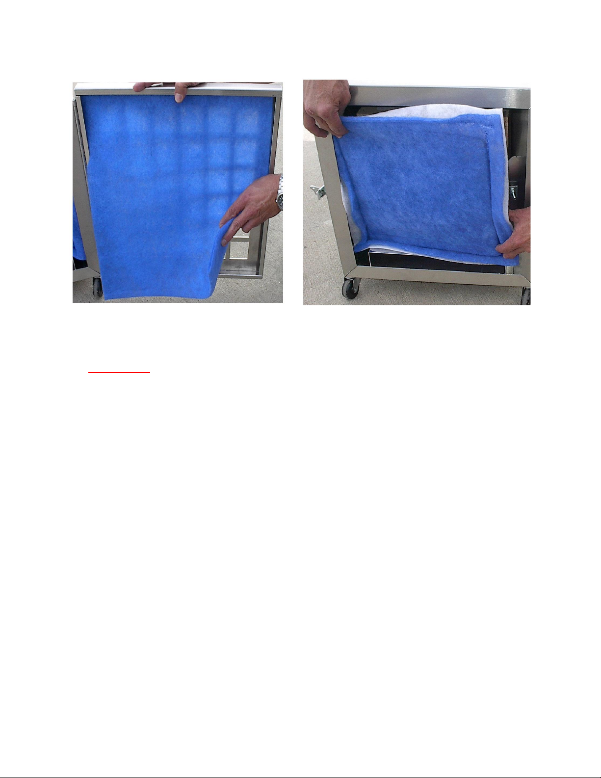
Fig. 2 Pre-filter Pad Fig. 3 Ring Panel Filter
4. FILTRATION:
4.1 First Stage Filter (Pre-filter Pad):
4.1.1 17.5” x 17.5” x 1”
4.1.2 Double Ply
4.1.3 Removes large particles up to 10 microns and larger from the air flowing through the
unit, thereby preventing premature loading of the second stage and HEPA filters. The
pre-filter pad (see fig 2) needs to be changed as it becomes loaded and the airflow
capacity of the unit decreases, or the pressure gauge at the control panel exceeds
1.9 inches of W.C. (see fig 1).
4.2 Second Stage Filter (Ring Panel Filter):
4.2.1 13” x 13” x 1”
4.2.2 Triple Ply Ring Panel
4.2.3 Removes particles up to 1 micron and larger from the air flowing through the unit,
thereby protecting the more expensive, HEPA filter. The ring panel filter (see fig 3)
needs to be changed as it becomes loaded and the airflow capacity of the unit
decreases, or the pressure gauge at the control panel exceeds 1.9 inches of W.C.
(see fig 1).

DOCUMENT NUMBER: OPMM-002E-R0
Proprietary Information: This document is the property of ADVANCED CONTAINMENT SYSTEMS, Inc. It shall not be copied
or duplicated and shall not be submitted to outside parties without the company consent.
Page 6 of 8 10/5/2016
Fig. 4 HEPA Filter
4.3 Third Stage Filter (HEPA):
4.3.1 12” x 12” x 11.5”
4.3.2 99.97% Efficient
4.3.3 Removes smaller contaminated particles up to 0.3 micron from the air flowing
through the unit and has an efficiency rating of 99.97%. The HEPA filter (see fig 4)
need to be changed as it becomes loaded and the airflow capacity of the unit
decreases, or the pressure gauge at the control panel exceeds 1.9 inches of W.C.
(see fig 1). Or depending on the use, every 700 hours per agency recommendations.
4.4 Proper disposal of filters explained in Section 5.4 of this manual.
5. FILTER REPLACEMENTS:
5.1 Pre-filter Pad Replacement:
5.1.1 Turn the unit off and make sure to disconnect the power supply cord from the unit.
5.1.2 Open the door and remove the contaminated pre-filter pad.
ATTENTION
PERSONNEL RESPONSIBLE FOR CHANGING FILTERS, SERVICING OR RELOCATING THE
UNIT, MUST WEAR APPROVED RESPIRATORS AND PROTECTIVE EQUIPMENT AND TO
FOLLOW SAFE WORK PROCEDURE.
DOCUMENT NUMBER: OPMM-002E-R0
Proprietary Information: This document is the property of ADVANCED CONTAINMENT SYSTEMS, Inc. It shall not be copied
or duplicated and shall not be submitted to outside parties without the company consent.
Page 7 of 8 10/5/2016
5.1.3 Fold in the sides of the contaminated pad and dispose of as per section 5.4.
5.1.4 Install a new pre-filter pad.
5.1.5 Close the door and fasten draw latch.
5.1.6 Reconnect the power supply cord, then turn the unit on, and check the pressure
gauge at the control panel.
5.1.7 If the pressure still exceeds 1.9 inches of W.C. on the unit’s gauge, the ring panel
filter also needs to be replaced.
5.2 Ring Panel Filter Replacement:
5.2.1 Turn the FA700 unit off and make sure to disconnect the power supply cord from the
unit.
5.2.2 Open the door and remove the contaminated ring panel filter.
5.2.3 Fold in the sides of the contaminated filter and dispose of as per section 5.4.
5.2.4 Install a new ring panel filter making sure to place it against the HEPA filter. This will
position the filter properly.
5.2.5 Close door and fasten the draw latch.
5.2.6 Reconnect the power supply cord, then turn the unit on, and check the pressure
gauge at the control panel.
5.2.7 If the pressure still exceeds 1.9 inches of W.C. on the unit’s gauge, the HEPA filter
also needs to be replaced.
5.3 HEPA Filter Replacement:
5.3.1 Turn the unit off and make sure to disconnect the power supply cord from the unit.
5.3.2 Open the door and remove the ring panel filters, as described in section 5.2.
5.3.3 Remove the HEPA filter by loosening the two nuts and rotating the tabs to the open
position.
5.3.4 Pull the HEPA filter out of the cabinet and dispose of as per section 5.4.
5.3.5 Inspect the gasket on the new HEPA filter housing before installation, to make sure
there are no gaps, cracks, or defects. Any defects in the gasket will allow leakage of
contaminated air through the unit.
ATTENTION
-THE NEW HEPA FILTER NEEDS TO BE THE SAME SIZE AND TYPE, AS THE ONE BEING
REPLACED.
- WHEN THE HEPA FILTER IS REPLACED, THE PRE-FILTER PAD AND RING PANEL FILTER
SHOULD ALSO BE REPLACED. THIS WILL HELP TO EXTEND THE LIFE OF THE HEPA FILTER

DOCUMENT NUMBER: OPMM-002E-R0
Proprietary Information: This document is the property of ADVANCED CONTAINMENT SYSTEMS, Inc. It shall not be copied
or duplicated and shall not be submitted to outside parties without the company consent.
Page 8 of 8 10/5/2016
5.3.6 Place the new HEPA filter in the unit with the gasket end facing the fan. Check to see
that the filter lies squarely on the base bracket.
5.3.7 Push the HEPA filter against the HEPA flange bulkhead and rotate the looking tabs
to the closed position.
5.3.8 Tighten the HEPA filter hold-down nuts securely to prevent air leaks.
5.3.9 Install ring panel filter as described in section 5.2.
5.3.10 Close door and fasten the draw latch.
5.3.11 Reconnect the power supply cord, then turn the unit on, and check the pressure
gauge at the control panel. If pressure still exceeds 1.9 inches of W.C. on the unit’s
gauge, consult your distributor.
5.4 Used filter disposal:
5.4.1 Used filters are considered contaminated waste and are to be disposed in
compliance with all applicable regulations. Personnel replacing filters must wear
personal protective equipment and follow safe work practices as per applicable
regulations.
6. REPLACEMENT PARTS LIST:
FA700 Replacement Part List:
Item: Part Number: Descriptions:
1 76010403 Motor 0.25HP Baldor #17E310W531
2 76252001 Blower 200 CFM DD9-4 #76M6062
3 38900724 Motor & Blower Assembly
4 Call Dist. HEPA Filter 12" x 12" x 11.5"
5 Call Dist. Ring Panel Filter 13" x 13" x 1"
6 Call Dist. PreFilter Pad 17.5" x 17.5" x 1"
7 3200100 Hepa Clip Kit
8 38900725 Control Panel Assy. (Item’s 8, 9, 10, 11 & etc.)
9 66020101 Gauge Pressure MinHelic #2--5005
10 72150236 Breaker 15 Amp Push Button
11 72270321 Motor Speed Control #KBWC-15K
12 72250301 Receptacle Recessed Male 15 AMP #5278
13 74100101 Linklock No Spring S-K3-1625-07
14 74100201 Linklock Keeper Plate K3-0334-07
15 74500102 Caster-2" Swvl Plug-in-Caster #5295/5299
16 74090520 Handle w/Spring (Blk)
17 71200204 Terminal Push On 16-14 Female Clear
Table of contents
Other ACSI Air Cleaner manuals


