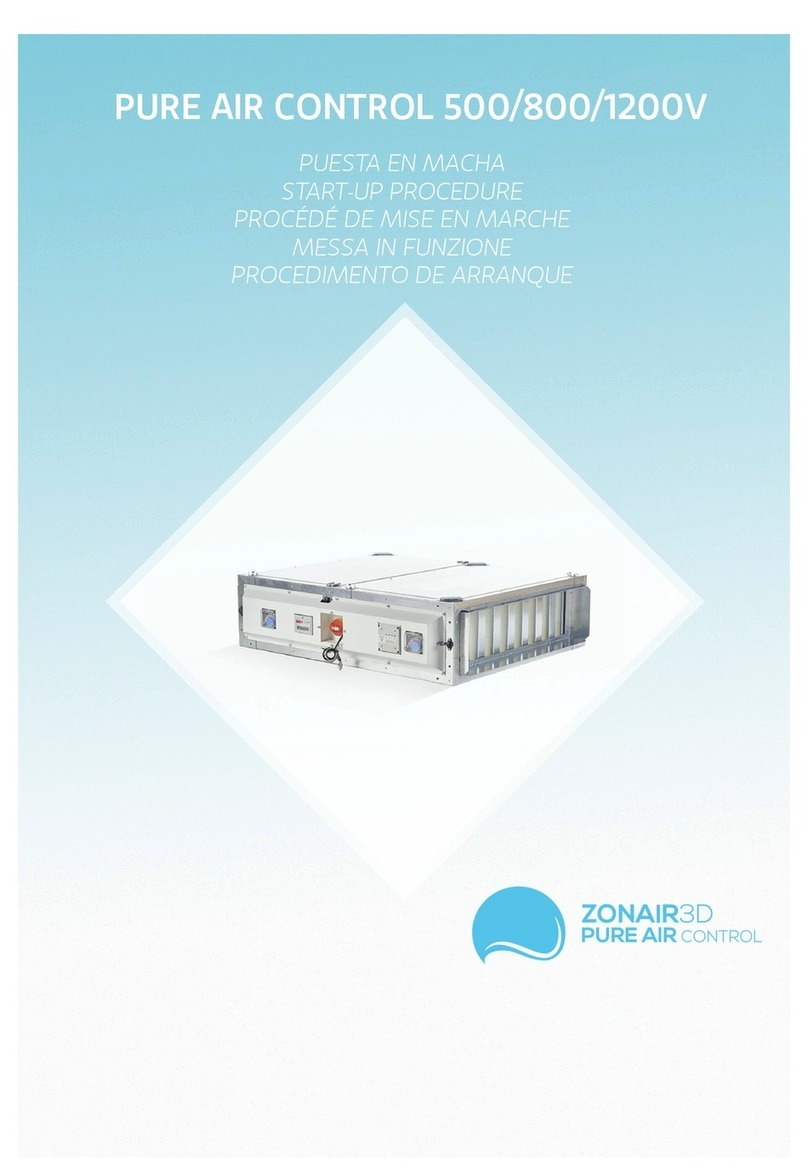
Zonair3D AIR PRO 500 User manual

P
A
P
A
P
800
P
800
P
500
P
500
P
1200
P
1200
P
800
1200
800
P
800
P
1200
P
800
P
AIR PRO
500
800
1200
USER MANUAL
ZONAIR3D


Zonair3D is a Spanish company
operating on all ve continents that is
engaged in the research and scientic
development of air purication systems.
In collaboration with a number of
scientic institutions and research
centres, Zonair3D works on the
development of solutions that offer
answers to unresolved needs in such
areas as health, wellbeing or buildings,
among others.
AIR PRO
This pioneering product is our response
to current environmental pollution and
our concerns over the constant and
ever-increasing deterioration of the
quality of the air we breathe.
Air Pro is an air purication
equipment specially designed for
indoor spaces. Its unique system lters
and puries polluted air, transforming
it into the best quality air, free from
contaminating particulate, free from
environmental ozone, and with toxic,
irritating and carcinogenic gaseous
pollutants reduced to levels of
comfort.
Pure air is essential for the
respiratory system to work properly,
it is an important factor in anti-aging
treatments, it enhances respiratory
pathway recovery following physical
exercise and it is of fundamental
importance to the existence of life.


7
7
8
8
9
9
10
12
12
12
14
19
21
23
24
25
25
25
25
26
27
27
1. SAFETY STANDARDS AND “CE” MARKING ___________________________________
2. GENERAL STANDARDS _____________________________________________________
3. UNIT LABELING ____________________________________________________________
4. HANDLING _________________________________________________________________
5. INSTALLATION
5.1. GENERAL INFO ________________________________________________________
5.2. IDENTIFICATION OF PARTS OF THE UNIT _______________________________
5.2.1. INTERIOR ELEMENTS
5.2.2. EXTERIOR ELEMENTS
5.2.2.1. WITHOUT SIDE INSPECTION COVER
5.2.2.2. WITH SIDE INSPECTION COVER
5.3. SETTING-UP LOCATION ______ __________________________________________
5.4. MAINTENANCE SPACE _________________________________________________
5.5. ASSEMBLY ____________________________________________________________
5.5.1. HORIZONTAL POSITION
5.5.1.1. SUSPENDED
5.5.1.2. ON BENCH
5.5.2. VERTICAL POSITION
5.6. ELECTRICAL CONNECTION AND CONTROL _______________________________
5.6.1. ELECTRICAL PRINCIPLE AND CONTROL DIAGRAM
5.6.1.1. AIR PRO 500
5.6.1.2. AIR PRO 800
5.6.1.3. AIR PRO 1200
5.6.2. CONNECTION PANEL DIAGRAM
5.6.2.1. ELECTRICAL WIRING CONNECTION AND CONTROL
DETAIL
5.6.2.2. FILTER STATUS NOTICE
5.7. MECHANICAL CONNECTION OF THE UNIT'S AIR PRESSURE INTAKES______
5.7.1. ELEMENTS POSITION AND PRESSURE INTAKES
5.7.2. CONNECTION DIAGRAM OF ELEMENTS AND SOCKETS PRESSURE
5.7.2.1. PRESSURE SWITCHES - DIFFERENTIAL PRESSURE PROBE -
PCB
5.7.2.2. DIFFERENTIAL PRESSURE SENSOR - ENGINES
5.8. CONNECTION TO THE ZONAIR3D INDOOR AIR QUALITY PROBE___________
5.8.1. PRINCIPLE OF CONNECTION DIAGRAM TO ZONAIR3D AIR QUALITY
PROBE
5.8.2. DETAIL OF CONNECTION WITH OR WITHOUT PROBE ZONAIR3D AIR
QUALITY
5.9. CONNECTING THE UNIT TO THE THE DUCT SYSTEM _____________________
6. START-UP PROCEDURE ____________________________________________________
7. EMERGENCY OPERATIONS _________________________________________________
8. PREVENTIVE MAINTENANCE ________________________________________________
8.1. MOTORS ___________________________________________________________
8.2. FANS ______________________________________________________________
8.3. FILTERS ___________________________________________________________
8.3.1. FILTER REPLACEMENT NOTICE SYSTEM
8.3.2. FILTER RECPLACEMENT
9. RECYCLING _______________________________________________________________
10. WARRANTY ______________________________________________________________

AIR PRO is a high-quality product that has been manufactured in strict compliance
with recognized technical regulations safety, and in accordance with EC standards.
Read this instruction booklet carefully, since it contains important information for
your safety during the installation, use and maintenance of this product.
We ask that you make sure the equipment is in perfect condition when you unpack
it, since any existing defect is covered by the manufacturer warranty.
1. SAFETY STANDARDS AND “EC” MARKS
The standards and recommendations indicated below reect current standards in the
eld of safety, and therefore are based primarily on meeting standards of a general
nature.
Consequently, we recommend that all personnel exposed to risks adhere strictly to
local regulations in force regarding hazard prevention.
ZONAIR3D is in no responsible for any damage or injury caused to persons or
objects resulting from failure to comply with safety standards, and any possible
modications to the product. The EC seal and statement of conformity serve as a
proof of the product’s compliance with applicable European Community standards.
ZONAIR3D engineers are rmly comitted to research and development to achieve
products with improved eciency that complies with current safety standards.
2. GENERAL STANDARDS
· Product risks have been analysed pursuant to the provisions of the Machinery
Directive. This manual contains information intended for all personnel exposed to
hazards, with the goal of preventing personal injuries or damage to objects resulting
from mishandling or improper maintenance.
· All maintenance service work (corrective and preventive) must be performed with
the equipment stopped and disconnected.
· Before connecting the power cable to the motors, make sure that the voltage on
the line matches the voltage indicated on the unit’s identication plate.
7AIR PRO 500-800-1200

3. UNIT LABELING
The unit comes with a variety of labels that must not be removed. Herewith sample
labels and meaning:
4. HANDLING
When unit received, unpack and make sure the packaging is intact; any defect may
indicate damage to the equipment. Review it carefully to make sure that no parts
are missing.
If there is any damage to the unit or the shipment is not complete, write down
the problems on the delivery slip and send a claim to the carrier. Also report any
problems to Zonair3D.
ICON / LABEL MEANING
Caution: the panel may fall once opened
Caution: cut off the power supply before
removing the panel
Caution: risk of entrapment
Air direction indication
Rating plate of the unit.
- Model
- Reference
- Serial number
- Frequency (Hz)
- Voltage (v)
- Maximum absorbed current (A)
- Maximum absorbed power (kW)
- Type of motor

5. INSTALLATION
5.1 GENERAL INFORMATION
Upon receipt of the equipment, the unit will be unpacked, checking its integrity. It will
be reviewed and it will be veried that no element is missing (see page 11).
You will nd, in addition to the equipment:
- A box with the anchor brackets or xing brackets that are supplied unassembled,
to be installed on site to the machine chassis. Includes 8 M6 Allen screws to x the
equipment to the desired surface.
- An individual absolute lter test certicate.
· The person responsible for receiving the equipment must ensure that the
characteristics of the available electrical supply are in accordance with the electrical
data on the rating plate of the unit
· Before fully setting up the equipment, it must veried that the place where the
equipment is going to be located is strong enough to support its weight.
· This must not be installed, under any circumstances, in ammable or explosive
environments, such as environments loaded with oil vapors, saline air or corrosive.
· The installation of the equipment can be dangerous, due to the material used, the
pressures in the system and the electrical components. Because of this only trained
and qualied personnel must install, service or repair the equipment.
· When carrying out operations inside the equipment, precautions must be taken to
interrupt the electric current in the isolator, in order to prevent possible accidents
with the moving parts of the equipment which might start running unpredictably, as
well as to prevent direct or indirect contact with any active part of the equipment.
· During the installation, the equipment must be leveled for a good adjustment of the
different units and a good opening of the registers.
· To check the perfect condition of the fan, the centering of the suction ring can be
checked by turning the turbine by hand.
9AIR PRO 500-800-1200

5.2 IDENTIFICATION OF EQUIPMENT UNITS
The main unit consists of the following differentiated sections: prelter, GRSystem
gas lter, fan and absolute lter. The following gure identies the main components
of the main module .
5.2.1 INTERIOR COMPONENTS
ABSOLUTE
FILTER
SECTION
FAN
SECTION PREFILTER &
GRSYSTEM
SECTION
Flujo
de aire
Flujo
de aire
Flujo
de aire
Mantenimiento
ABSOLUTE
FILTER
FAN
PREFILTER G4
GRSYSTEM
GRSYSTEM
FILTER TIGHTENING
KNOBS
LOBED
ABSOLUTE FILTER
TIGHTENING
KNOBS
LOBED
L
WH

Air
Flow
11 AIR PRO 500-800-1200
1 - H14 PRESSURE SWITCH
2 - PCB (Printed circuit board) (*)
3 - ROTARY SWITCH (**)
4 - DIFFERENTIAL PRESSURE
SENSOR5
5 - G4 PRESSURE SWITCH
7 - G4 PRESSURE TAP “+”
5 - G4 PRESSURE TAP “-”
6 - INPUT “-” G4 PRESSURE SWITCH
8 - INPUT “+” G4 PRESSURE SWITCH
12 - FRONT "+" (A.G. REGULATOR
FLOW)
10 - REVERSE "-" (A.G. REGULATOR
FLOW)
9 - PRESSURE SOCKET “-” FAN
11 - PRESSURE SOCKET “+” FAN
3 - SOCKET “+” H14
1 - SOCKET “-” H14
4 - INPUT “-” H14 PRESSURE SWITCH
2 - INPUT “+” H14 PRESSURE
SWITCH
Maintenance Maintenance
Air
Flow
Maintenance Maintenance
1 2 3 45
2
1
3 11 8
7
56
12109
4
5.2.2 EXTERIOR ELEMENTS
5.2.2.1. WITH SIDE INSPECTION COVER
5.2.2.2 WITHOUT SIDE INSPECTION COVER
PRODUCT
RANGE FLOW
(m3/h) MEASUREMENTS
H X W X L (mm)
POWER
(KW) ELECTRICAL
POWER SUPPLY WEIGHT
(Kg)
AIR PRO 500 500 310 x 972 x 1104 0,164 1F/230 V, 50-60 84
AIR PRO 800 800 310 x 972 x 1104 0,328 1F/230 V, 50-60 85
AVAILAB.
PRESS.
(Pa)
303
245
AIR PRO 1200 1200 353 x 972 x 1104 0,518 1F/230 V, 50-60 92 390

5.3 SETTING-UP LOCATION
Avoid installing the device in areas close to heat sources and humid areas where the
it may come into contact with water.
It is advisable to place the device in a location where the installation is easily accessible.
Provide sucient space for maintenance and connection.
5.4 MAINTENANCE SPACE
The person installing the equipment must allow space which is free of obstruction
to be able to freely access the device for maintenance. The space required will
depend on the side of the device where the extraction is made. The equipment is
provided with registers to access the lters and fans.
5.5 MOUNTING POSITION
VERTICAL
üüüüü
Filters and fans
maintenance
PRODUCT
RANGE
AIR PRO 500
DIMENSIONS
H x W x L (mm)
310x972x1104
AIR PRO 800 310x972x1104
AIR PRO1200 353x972x1104
üüüüü
suspended on bench
üüüüü
üüüüü
HORIZONTAL TRANSVERSAL
üüüüü
500 A 300
Maintenance
Air
ow
300 B 300

13 AIR PRO 500-800-1200
maintenance
5.5.1 HORIZONTAL POSITION
5.5.1.1 SUSPENDED
For ceiling mounting, you must:
· Assemble the 8 brackets together with their screws in the 8 corners of the equipment
supplied with the product.
· The upper brackets will act as interns for the braces and the lower brackets as a
grip and suspension of the equipment, the assembly of an anti-vibration system is
recommended.
· No obstacle should prevent or reduce the passage of air both in the suction and in the
impulsion.
5.5.1.2 BENCH/FLOOR MOUNTED
For oor mounting, you must:
· Assemble the 4 brackets together with their screws in the 4 corners of the bench
support equipment. These brackets will NOT be used to join them to any type of anti-
vibration system.
· The classic bench system is based on a support structure for the equipment (which
can be joined with the brackets mentioned in the previous point) and said structure will
be isolated from the supporting ground by means of an anti-vibration system, as shown
in the attached diagram .
· No obstacle should prevent or reduce the passage of air both in the suction and in the
impulsion.
OK
CEILING MOUNTED
maintenance
Air
ow
Air
ow
registro
maintenance maintenance

5.5.2 VERTICAL POSITION
5.6 ELECTRICAL CONNECTION AND EQUIPMENT CONTROL
The equipment leaves the factory fully wired and tested, thus being a plug and play equipment.
Qualied personnel will only have to power the equipment electrically and, if they have the
ZONAIR3D air quality probe, carry the necessary control cables. See point 5.6.1, general diagram
of electrical connection and control.
· The installation must be carried on by qualied personnel.
· Cables complying to the section with the current directives must be installed preventing heating
and a voltage drop higher than that allowed. The current regulations must be complied with and,
at all times, the designer's criteria must be followed.
· Before connecting the cables, check that the electrical installation is disconnected and that
there is no voltage between the cables.
· Once installed, the device must comply with the following Directives:
- Low Voltage Directive 2014/35/EU
- Safety in machines 2006 / 42 / EC
- Electromagnetic Compatibility Directive (CEM) 2014/30/EU
- Ecodesign for fans EU 327/2011
- Hazardous substances 2011/65/EU
· Once these operations have been carried out, it is necessary to verify the tightening of all the
electrical connections (a badly tightened cable can cause irreparable damage).
· Check to make sure the electrical resistance between earth and any electrical terminal is greater
than 1 megohms. If it is not, do not start up the unit until the electrical short has been located
and repaired.
· As a safety measure, if the fan runs out of voltage, it must be made so that all other electrical
elements are without voltage.
maintenance
air ow air ow
ATTENTION: You must
ensure that the wall
where the equipment is
installed is suitable for
supporting its weight.

15 AIR PRO 500-800-1200
5.6.1 ELECTRICAL PRINCIPLE AND CONTROL DIAGRAM
5.6.1.1 – AIR PRO 500

5.6.1.2 – AIR PRO 800

17 AIR PRO 500-800-1200
5.6.1.3– AIR PRO 1200

5.6.2 CONNECTION PANEL DIAGRAM
5.6.2.1 ELECTRICAL AND CONTROL WIRING CONNECTION DETAIL
IMPORTANT: If the customer has NOT opted to purchase the probe, they do NOT
have to touch ANYTHING on the terminal block that comes from the factory,
that is, cables 18 and 20 have to go together (bridge mode). If the client HAS
purchased the probe, they must separate cables 18 and 20 from the terminal strip
for the correct operation of the equipment, in this way the probe will govern the
equipment based on the air quality.
5.6.2.2 NOTICE DETAIL OF FILTER STATUS
The equipment has an integrated system (regardless of the probe) of leds that
indicates the status of the lters, when the leds are off, the status of the lters
is correct, when the leds turn red, it indicates that the lter must be changed. led
lter on.
IMPORTANT NOTE: When changing the GRSystem lter (GRSV gas lter) you
have to access the inside of the Electronic Control Board (PCB) (see situation in
point 5.2.2.1) by unscrewing the front plastic cover and carry out the following
action, press button P1 RESET CARBON/COAL continuously until the red alarm
led is deactivated.
THE LIGHT ABOVE SHOW THAT THE INDICATED
FILTER IS OVERFILLED. IN THAT CASE, FOR
THE CORRECT WORK OF THE SYSTEM, PLEASE
CONTACT YOUR DISTRIBUTOR TO REPLACE THEM.
GRSV F7 G4 H14 FILTER
SUBSTITUTION
B
A
C
(A) Black cable = 230V power supply
(B) Upper gray cable = planned connection to the Z3D air quality sensorN
for lter review notice, there are 2 cables marked with numbers 5 and 6 that
correspond to the numbers where they have to be connected inside said probe.
(C) Lower gray cable = provision for connection to the Z3D air quality probe for
purier ON/OFF control based on indoor air quality limits, there are 2 cables
marked with the numbers 18 and 20 that correspond to the numbers where
they have to be connected inside said probe.
See diagrams point 5.8.1.

19 AIR PRO 500-800-1200
5.7 MECHANICAL CONNECTION OF THE EQUIPMENT AIR PRESSURE INTAKES
5.7.1 LOCATION OF ELEMENTS AND PRESSURE TAPS
* PS600 pressure switch for H14 of PAC1200V
** PS300 pressure switch for all G4 and H14 of PAC500V and PAC800V
· To access the pressure sensor connection system, it is necessary to remove the side
register.
· Once said register is unscrewed, we access the mechanical connection of the
equipment control system
1 - H14 PRESSURE SWITCH (*)
2 - PCB (Printed circuit board)
3 - ROTARY SWITCH (**)
4 - DIFFERENTIAL PRESSURE SENSOR5
5 - G4 PRESSURE SWITCH
7 - PRESSURE SOCKET “+” G4
5 - PRESSURE TAKE-OFF “-” G4
6 - INPUT “-” G4 PRESSURE SWITCH
8 - INPUT “+” G4 PRESSURE SWITCH
12 - FRONT "+" (A.G. REGULATOR
FLOW)
10 - BACK "-" (A.G. REGULATOR
FLOW)
9 - ENGINE “-” PRESSURE TAKE-OFF
11 - ENGINE “+” PRESSURE SOCKET
3 - SOCKET “+” H14
1 - SOCKET “-” H14
4 - “-” INPUT H14 PRESSURE SWITCH
2 - “+” INPUT H14 PRESSURE SWITCH
Mantenimiento Mantenimiento
Air
Flow
Air
Flow
Air
Flow
Air
Flow
Maintenance Maintenance
1 2 3 45
2
1
3 11 8
7
56
12109
4
5.7.1.1. SIDE REGISTRATION CLOSED
5.7.2.2. WITH SIDE INSPECTION UNCOVER
BUTTON
RESET
COAL

5.7.2 CONNECTION DIAGRAM OF ELEMENTS AND PRESSURE PORTS
5.7.2.1 PRESSURE SWITCHES - DIFFERENTIAL PRESSURE PROBE - PCB
PAC500V
PAC800V
PAC1200V
This manual suits for next models
2
Table of contents
Other Zonair3D Air Cleaner manuals

Zonair3D
Zonair3D AIR+ 300 S User manual

Zonair3D
Zonair3D Pure Airbox Home 500 S User manual

Zonair3D
Zonair3D d2itsu PAR 100 User guide

Zonair3D
Zonair3D AIR MOVE+ User manual

Zonair3D
Zonair3D AIR+ 50 User manual

Zonair3D
Zonair3D AIR MOVE+ User manual

Zonair3D
Zonair3D AIR+ 600i Instruction manual

Zonair3D
Zonair3D PURE AIR CONTROL 500V Manual

Zonair3D
Zonair3D PURE AIRBOX User manual

Zonair3D
Zonair3D AIR PRO 2000 User manual