ACUVANCE XARVIX XX User manual

XARVIS XX Owner's Manual
Repair Conditions
Note that if the date and location of ESC purchase are not entered on the warranty card, you will
be charged for repairs even within the warranty term.
●If a failure occurs within three months of purchasing the ESC, write the symptoms of the problem
and operating conditions in the section below and attach this to the product. For repair, send the
ESC to the distributor where you purchased the product or directly to ACUVANCE (Technical
Service Department).
●ACUVANCE assumes no responsibility for damage or losses that occur during transportation.
Please take note of this beforehand.
●When listing the symptoms for a repair request, you can conveniently use the repair request
sheet on the ACUVANCE homepage and then send this along with the warranty card.
(Click the “repair” section located in the upper-right side of our website. Then click “repair
request sheet”, located on the left side.)
Warranty
Item
Manufacture
no.
XARVIS XX Purchase
date
Customer
Address
E-mail
Phone
number
Name
Warranty
term
3 months from purchase date
Phone no.@( )
Repair card
1. Symptoms
Write the symptoms of the problem,
giving as much detail as possible.
2. Payment for repair charges
I would like to be contacted if there is compensation
※Though it depends on the details of the repair, indicating in advance that no contact is necessary will
normally shorten the time is takes to complete the repair.
1. Parts that can be repaired.:
•Internal electronic circuitry
Damage caused by incorrect connection, inter-terminal shorting, or driving is not covered by
warranty.
2. Note that this device will not be covered under warranty if the housing has been opened.
3. ACUVANCE assumes no responsibility for damage to the receiver or servo caused by the
incorrect connection of this product.
4. Note that if the repair card (located below) or the repair sheet (on the homepage) is not properly
filled out, repair and return of the ESC may be delayed.
(M/D/Y) / /
Shopname(address,andphone.no.)
7F, Shin-Osaka Marubiru Annex 1-18-22
Higashinakajima Higashiyodogawa-ku
Osaka 533-0033 Japan.
FAX +81-6-6379-1190
www.acuvance.co.jp/english
Technical Service Dept.
330290-1

32
PRECAUTION FOR USE
WARNING
WARNING
CAUTION
DANGER
Instructions that the user must observe to prevent serious injury.
Instructions that the user must observe to prevent accidents.
Useful information for handling this product.
Before using this product, carefully read the important warnings
described in this instruction manual to understand the instructions thoroughly.
DANGER
Aboutbatteries
Topreventfumes,fire,orburns
DANGER Topreventfumes,fire,orburns
AboutcableConnections
DANGER Topreventburns
About
Toavoidaccidentsorproductfailure
Handlingprecautions
WARNING
P.4
P.6〜P.9
P.10〜P.21
INDEX
Specifications
6.0V〜8.5V
Continuous/spontaneous max current
Compatible motors
Dimensions W30.5×D35.0×H20.5mm
Weight 47. 2 g
FEATURES
Power Supply
Regulator for receiver/servo 6V/5A or 7.4V/5A output
How to conHow to connect the ESC
Preparations Before Driving Tuning
the Driving Experience
Max. current of battery
Sensored motor - unrestricted (when boost turbo is disabled)
Improper use of the battery is very dangerous. The battery must be handled carefully.
Incorrect wiring or short-circuiting of wiring may cause re or fumes. Before
connecting or disconnecting the battery to or from the speed controller (ESC), be
sure to turn offthe power switch of the ESC. When the battery is not in use,
disconnect it from the ESC or charger, and store it in a suitable location free of any
loose wires or screws.
Incorrect wiring may cause re or fumes that can damage both the ESC and
battery beyond repair.
The surface of the body can be extremely hot after heavy load driving. Please
handle the unit carefully after operation to avoid risk of burn.
Do not modify the ESC in any way. Use it only for its intended purpose. Keep the
ESC away from ames or seat. Avoid splashing any liquid, such as water, on the
ESC.
Thank you for choosing XARVIS XX. This product is a high-performance speed
controller for drivers seeking the top end. Please read this instruction manual
carefully before using this product, and use it correctly and safely. Please keep it
carefully after reading.
Please check our website and official Twitter for details on the features and the
latest information. (@ACUVANCE_JAPAN)
This new ESC is equipped with a high-performance MOSFET of the industry's
highest peak
(currently when this product was released / according to our research).
As a result, output performance such as torque and efficiency has been greatly
improved.
XARVIS's unique “bridge type FAN floating structure” is further evolved to
greatly increase the ventilation capacity.
Equipped with two ACUVANCE cooling fan terminals (including FLEDGE fan)
Equipped with capacitor mounting terminal
Equipped with reverse battery protection circuit (see page 22)
BEC voltage switching (6.0V / 7.4V) function (see page 20)
Supports bidirectional communication with TAO II, Ne-St, FUTABA S.BUS
system compatible transmitters, etc.
※This product needs to be updated to use the S.BUS system (see ACUVANCE
website).
Equipped with a new program control circuit to secure additional setting items
for only XARVIS XX
FEATURES
4 5
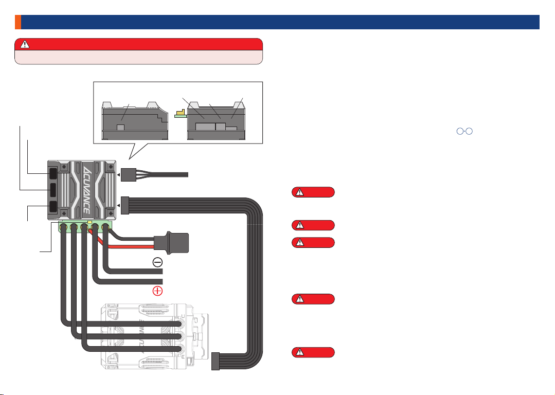
PART NAMES AND WIRING
Be careful not to reverse the battery poles. Doing so can cause the ESC to fail.
If the sensor cable is not connected, has not been properly inserted, has been
disconnected, or is loosely connected, all the LEDs will blink (highspeed
blinking). While in this state, all operations will not be received. If this occurs,
check the connection for the sensor cable or replace the cable.
When inserting the connector, pay attention to the way in which it being inserted.
If inserted backwards, the device will not operate.
Be sure to match the cables to the symbols A, B, and C on the ESC. Failure to
follow this precaution can result in loss of control over the motor speed, or
subject the ESC and motor to large currents. Unlike brushless motors without a
sensor, swapping these cables does not change the rotating direction of the
motor. If necessary, change the direction of rotation at the ESC※.
※To switch the direction of rotation, it is essential to have the rotation direction
change function in the ESC. This machine has this function (P.16)
When replacing the motor cable, use a soldering iron with a broad tip and high
output rating (as high as 60 W) and work swiftly. A soldering on with the low
output rating will not melt enough of the solder resulting in a poor soldering
connection which can cause cables to loosen under vibration or loose
connections. Also, subjecting the internal parts to excessive heat over prolonged
periods (10 seconds or more) can damage them. (Be careful not to shortcircuit
the terminals with solder)
Be sure to use screws with a length of 8 mm or less to secure the motor to the
motor mount. If the screw is too long, it may interfere with parts inside the motor,
resulting in malfunctions such as short circuit.
WARNING
WARNING
WARNING
WARNING
WARNING
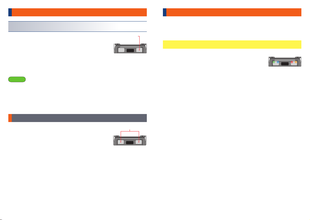
• POWER BUTTON
• LINK TERMINAL
• SET BUTTON
• COOLING FAN CONNECTION TERMINAL
It is the button to turn the unit ON or OFF.
It is used for setting change in the XARVIS XX main unit. It is also used to switch
between "ESC mode" setting of the main unit, and "Link mode" setting with TAO
II.
ACUVANCE optional cooling fan or fan connection terminal with our motor.
It doesn't matter if you use either terminal ①or ②.
Since it is designed exclusively for ACUVANCE cooling fan, other manufacturers'
cooling fans cannot be used.
(If you use a fan of a different brand, the fan may be damaged.)
Terminal for communication with TAO II, Ne-St. Air-Link Adapter (OP-15065),
S.BUS Adapter (OP-15067), etc. are also connect here.
DANGER To prevent fumes, re, or burns
1 2
RX
FANSENSOR -+S
Please connect as
shown below
Sensor cable
Battery cables
Motor Cable C
Motor Cable A
Motor Cable B
XARVIS XX body
Sensored Brushless Motor
RX Cable
POWER button
SET button
[Behind]
Reverse
connection
alert LED
( s e e P. 2 2 )
The throttle channel(CH2)
from the receiver
Capacitor
RX TerminalSensor Cooling
FAN②
Rear LayoutSide Layout
LINK terminal
- + S
FAN
Cooling
FAN①

6 7
PREPARATIONS BEFORE DRIVING
While the blue LED is blinking, set the throttle
on the transmitter to the maximum forward
position and press the set button on the ESC
once. The red LED will start blinking.
※If the red LED does not blink after pressing the
set button with the throttle at the maximum forward
position, set the throttle to the maximum reverse
(brake) position and then press the set button
once.
While the red LED is blinking, set the throttle
on the transmitter to the maximum reverse
position of Step 4, and press the set button on
the ESC once. All LEDs will blink three times.
4
5
Important
Caution
If you performed the procedure described by the ※under Step 4 above, <<Setting
the high point>>, switch the throttle channel on the transmitter between normal and
reverse after completing the initial setting for all transmitter positions.
The throttle position for the transmitter may become misaligned due to changes or
deterioration over time.If the LED lights are ashing while the ESC is in standby
mode, readjust the initial settings for the transmitter.
When using for the first time, the neutral position of ESC with the transmitter you
have will not match. If you try driving before the initial setting is completed, the
motor may start rotating at the same time as the switch is turned on. Since it is
very dangerous, be sure to perform the following "initial setting of the radio
throttle position" when turning on the power for the first time.
(The motor will not rotate during initial setting.)
Initial setting of radio throttle position
How to Calibrate
Supports SANWA super response <SSR> mode
Immediately after purchasing or immediately after replacing the transmitter, it is
necessary to store the neutral point, forward MAX point and reverse (brake) MAX
point of the transmitter in the ESC. Follow the procedure below.
Before setting, please set all settings (EPA = endpoint adjustment, maximum
braking amount, etc) for the throttle of the transmitter to a neutral position (zero
value). If the settings are different, the ESC may not detect the throttle input and
calibration will not be performed successfully.
When performing the initial setting, be sure that the sensor cable is connected to
the motor and ESC. If the sensor cable is not connected, has not been properly
inserted, has been disconnected, or is loosely connected, all the LEDs will
blink(high-speed blinking). Check the connection for the sensor cable or replace
the cable as all operations will not be received while it is in this state. Also, in
assition to when performing the initial settings, the sensor cable should always be
connected when the vehicle is being driven.
The three motor cables (A, B, C) may be left disconnected but be careful to not
have the cable connectors touch each other as they will short.
If performing the initial settings with the motor cables connected, secure the motor
in a motor mount or other device, and remove the pinion gear to keep the car from
moving unexpectedly.
Be sure the ESC power is turned off,and make sure the ESC is properly
connected to the battery, motor (only the Sensor cable needs to be connected),
and receiver. Then turn the transmitter power on.
If you press and hold the POWER button
for 2 to 3 seconds while the power is OFF,
the LED green blinks 3 times at the same
time, the LED green starts blinking and the
initial setting mode is entered. Then
release the POWER button.
While the LED blinks green, set the transmitter
throttle to the neutral position and press the
POWER button briefly. After that, the blue LED
will blink.
1
2
3
Preparations
Preparations
Preparations
LED Green · Orange
Blink for 3 seconds
at the same time
LED blinking
Press and hold the POWER button
for 2 to 3 seconds
Green
blinking
LED
changes to
Blue
blinking
LED
Press POWER button
Blue
blinking
LED
changes to
Red
blinking
LED
Press POWER button
Neutral position
Max.forwardposition
Red
blinking
LED
changes to
All LEDs
Blink three
Times
Press POWER button
Max.reverseposition
This completes the initial settings for the transmitter
positions. The ESC automatically changes to the
standby mode (p. 8).
<<Before making calibration>>
<<Calibration mode>>
<<Setting of the neutral point>>
<<Setting of the high point>>
<<Before making calibration>>
*“SSR mode” is an original system from Sanwa Denshi Co. Ltd.
Powering OFF
Press and hold the POWER button for 2 seconds to
turn off the power.
8 9
PREPARATIONS BEFORE DRIVING
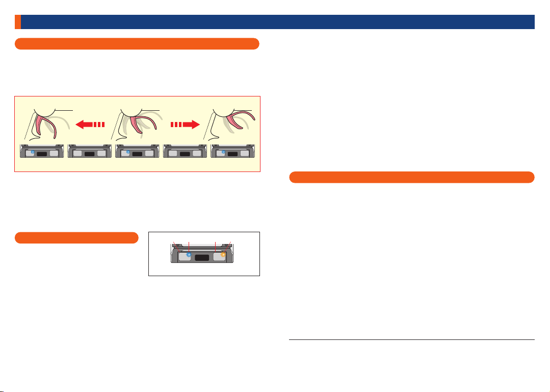
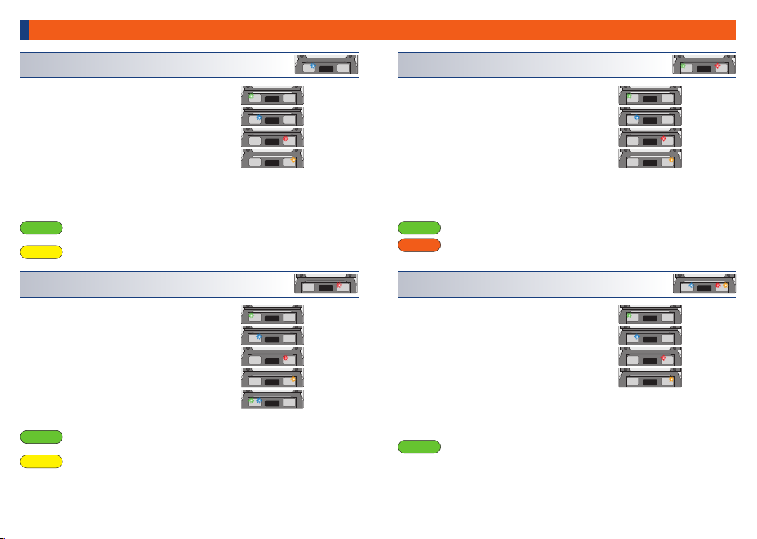
Checking standby mode
At the time of shipment, the standby
mode is as shown in the figure on the
right. Each LED has the following
meaning.
[Important] Safety feature for driving in reverse
On radio controlled cars, the same throttle controls are used for braking and
driving in reverse. This can cause car to move backward when the intention is to
apply the brakes. Suddenly trying to reverse the motor while it is rotating forward
can place severe stree to the gears, motor, and ESC, sometimes resulting in
internal damage. The XARVIS XX is equipped with the following feature to
prevent this.
After applying the brakes, before reversing, the ESC will wait 1 second or more
for the throttle to return to neutral and for the the motor to go from rotating in a
forward direction to coming to a complete stop (it will not go into reverse within
the span of 1 second).
This feature prevents unintentional reversing even if the reverse drive feature is
set ON on the ESC. It prevents damage to the drivetrain of the car and potential
collision with other vehicles, as well as many other possible problems, and is
essential to allow short braking action when turning corners.
① ② ③ ④
Stanby mode at time of shipment
This completes the preparation before driving. Connect the motor and enjoy
driving.
When using lithium polymer batteries, set the cutoff voltage before driving to 3.2V/cell (1
recommended)(P.16)
Verifying the transmitter positions have been correctly set to their initial settings
The standby LED (see below) should be the only one illuminated when the throttle is in
the neutral, maximum forward, and maximum reverse (brake) positions. If the Stanby
LED is unlit in all other positions, the initial setup has been completed properly.
(The standy LED is the only LED that alternately illuminates and goes out when
adjusting the throttle)
If the standby LED does not follow this lighting pattern, the initial setting was not
completed properly. Make sure the throttle related adjustment on the transmitter
are initialized and the RX cable is properly connected to the receiver. Then, retry
the initial setting procedure.
※Depending on the configuration of the vehicle, the car may move in reverse when the throttle
is operated in the forward direction. If your car displays this behavior, change the rotation
direction of the motor (P.16 ).
Neutral positionMax. forward position Max. reverse position
Standby LED lit unlit Standby LED lit unlit Standby LED lit
Note, this safety feature cannot be disabled. However, as detailed in [Reverse
drive ON/OFF and motor rotating selection](P.16), when configuring to
crawleroriented settings, vehicle movement that occurs once the throttle is
placed in the brake position will be specialized for reverse driving (the brake
will not work), thus disabling this function.
①
※
LED<green> : Factory shipped condition = unlit
If the battery voltage becomes lower than the cutoff voltage (P.16) while
driving, the green LED will blink and the car will drive at extremely low
speeds. If this occurs, replace the battery.
②LED<blue> : Factory shipped condition = lit
Standby LED when setting mode (P.10) is in ESC mode. Unlit during Link
mode.
※Under "ESC Mode", <blue> LED will be blinking if the program selected
(P.12) is "Boost/Turbo Disabled", or both "Full Boost Timing"(P.17) and "Full
Turbo Timing" (P.19) are disabled.
②LED<red> : Factory shipped condition = unlit
Standby LED when setting mode is in Link mode. Unlit during ESC mode.
※Under "Link Mode", <red> LED will be blinking if the program selected (P.12)
is "Boost/Turbo Disabled", or both "Full Boost Timing"(P.17) and "Full Turbo
Timing" (P.19) are disabled.
②LED<orange> : Factory shipped condition = lit
Illuminated when the reverse drive feature (P.16) is set to ON. Unlit when set to
OFF.
※
※
※
If the ESC heats up to temperature limits while driving, the motor will remain
at low speed and the Orange LED will blink. If this situation occurs,
discontinue operation until the ESC temperature drops back to ambient
temperature. If the Orange LED starts blinking after driving for only a brief
period of time, check to see if the gear ratio settings are overloading the
motor.

10 11
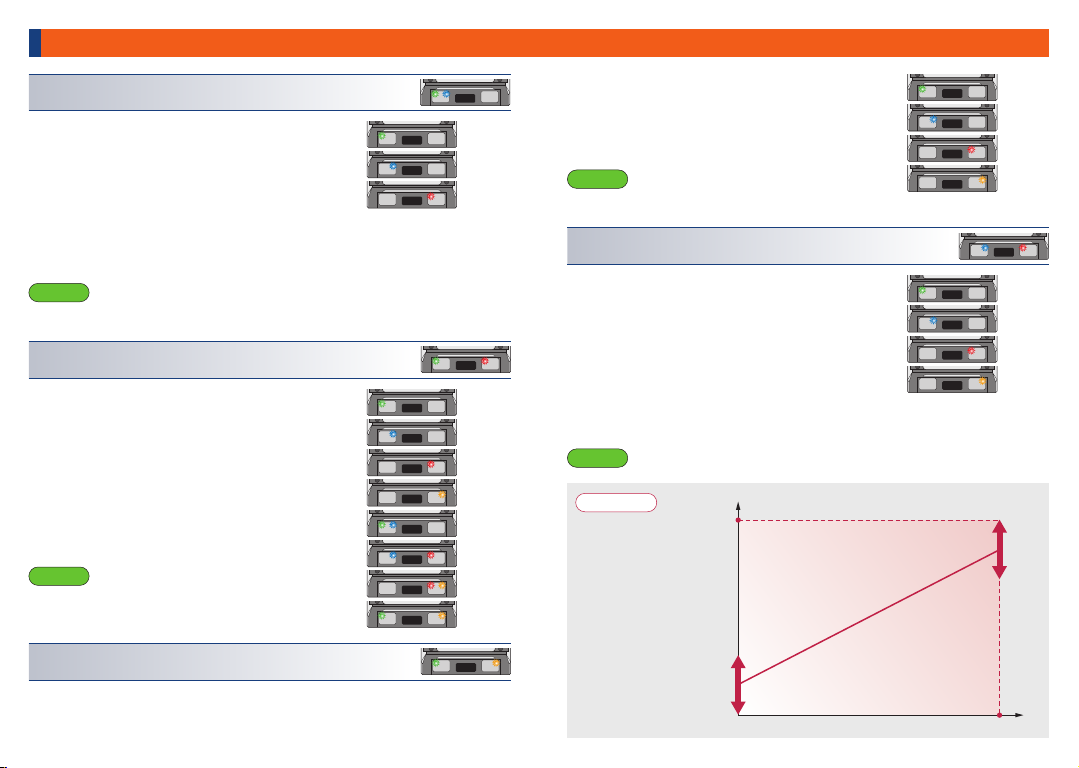
Selecting setting modes
Flow for changing setting and ESC mode
First, select either [ESC mode] or [Link mode].Select ESC mode to adjust various
features on the ESC, or Link mode to change function settings for the effector. At
time of shipment, ESC is set to ESC mode.
Select mode (when Setting mode = ESC mode
In Standby mode (P.8), quickly press the set button once.
The green LED will start blinking indicating the ESC is in
Select mode. (While in Select mode, the motor will not rotate
even if the transmitter throttle is operated.)
In Select mode, set the LED to the item you want to the check the value of,
after 2 seconds the LED representing the item & the LED representing the
value of the item will blink alternatively. ( The LED indicate the item
selected> <The LED indicate the value of the selected item)
Pressing the SET button once returns to the Select mode.
Refer to P.12 to 20 for the meaning of each displayed values.
With "Load Program", the value LEDs won't always be displayed.
Each time the SET button is pressed briefly, the flashing LED is switched to
indicate the currently selected setting item (see the setting items below for
details). Also, pressing the SET button twice shortly will return to the previous
item.
1
2
Selecting
Setting Modes
Repeating the same procedure alternates between [ESC mode](blue) and [Link
mode](red).
Important
The numerical setting ranges and unit of adjustment differ depending on the mode
selected (P.12 to 20). Refer to the following section for setting procedure in ESC
mode, or the instruction manual supplied with the programming card for setting
procedures in Link mode.
Select the setting to change
Select mode (P.11)(Driving disabled)
Select the save
destination
(P.20)(Driving disabled)
Change the value in the selected item
Select mode > Save destination selection
Quickly press the set button 4 times in
rapid successions.
Standby mode > Select mode
Quickly press the set button
once
Select mode > Standby mode
Quickly press the set button 3
times in rapid succession.
Save destination selection mode > Standby mode.
After selecting the save destination, press the set button
for 2 seconds or longer
Select mode > Setting mode
After selecting the item you wish to change,
press and hold the set button for 2 seconds
or longer
Select mode > Setting mode
Set to desired value, then press and hold
the set button for 2 second or longer.
Select mode
(blinking green LED)
Neutral brake power adjustment is selected
(Blinking orange LED)
(For details of each item, see the following pages)
Description of each blinking LED pattern
[Verifying your current settings]
TUNING THE DRIVING EXPERIENCE
(Ex.)
In standby mode, press and hold
the set button for 4 seconds or longer.
The LEDs (blue & red) alternately blink
indicating the setting mode is now active.
Press the set button
For 4 seconds or longer
Press the SET
Button once
Standby mode
※If the initial settings have not been completed, the following procedure cannot be performed.
[Green flashing twice] Load Program
[Blue flashing twice]Drive Frequency
[Red flashing twice]Neutral Brake Frequency
[Orange flashing twice]Brake Frequency
[Green+Blue flashing twice]Initial Speed
[Green+Red flashing twice]Neutral Brake Power
[Green+Orange flashing twice]Initial Brake Power
[Blue+Red flashing twice]Full Brake Power
[Grn+Blu+Red flashing twice]Operation mode
[Blu+Red+Org flashing twice]Cutoff Voltage
[Green flashing 4 times]Full Boost Timing
[Blue flashing 4 times]Boost Start RPM
[Red flashing 4 times]Boost Stop RPM
[Grn+Red flashing 4 times]Full Turbo Timing
[Blu+Red+Org flashing 4 times]Turbo Start Time
Green Orange
(p.8)(Driving enabled)
Changes will not be saved.
※
※
※
※
Setting mode (P.12)(Driving disabled)

12 13
Setting mode (in ESC setting mode)
While in Select mode (P.11), move the LED to the setting to be changed using the
SET button. Press and hold the SET button 2 seconds or longer. This activates
the Settings mode. (While in Settings mode, the motor will not rotate even if the
transmitter throttle is operated.)
②
Changing to Setting mode
In the select mode(green blinking twice), press
the SET button for 2 seconds or more to enter
the setting mode . Each time the SET button is
pressed briefly, the LED pattern changes and
the program changes accordingly as shown
on the right. Align the LED with your favorite
program, and press the SET button for 2
seconds or more. The program is now set and
the LED returns to the select mode (green
blinking). It is also possible to call the preset
program and change each function to the
setting of your choice.
①
Important
When "boost / turbo disabled" is selected, boost and turbo function (item (11) and
later described below) can not be used. In this case, ⑪to ⑮are skipped in select
mode. Also, the timing angle is fixed at 0 °.
Caution If the power is turned off without saving to a user program, the settings will be lost.
Drift
Boost / Turbo Disabled
Touring
Offroad 2WD
Offroad 4WD
User program①
User program②
TUNING THE DRIVING EXPERIENCE
In select mode, the blue LED blink twice, press the SET button for 2 seconds or more to
enter the setting mode. Each time the SET button is pressed once, the lighting LED
changes and the drive frequency changes as shown on the right.
Adjust the LED to the setting of your choice and press the
SET button for 2 seconds or more. The set value is
validated and it returns to select mode. The changed value
will be reset if the power is turned off without saving.
Please save your settings before tunring your unit off
( P. 2 0 ) .
Commentary
The lower the value = strong initial punch/lowered
smoothness. The higher the value = small initial
punch/ increased smoothness
4KHz
8KHz
16KHz
24KHz
2KHz
4KHz
8KHz
16KHz
③
In the select mode with the red LED flashing twice, press
the SET button for 2 seconds or more to enter the setting
mode. Each time the SET button is pressed once, the LED
pattern changes and the neutral brake frequency changes
as shown on the right. Adjust the LED to the setting of your
choice and press the SET button for 2 seconds or more.
The set value is validated and it returns to select mode. The
changed value will be reset if the power is turned off
without saving. Please save your settings before tunring
your unit off (P.20).
Commentary
The lower the value = quicker braking
The higher the value = smoother braking
This is the area to store each set item on this unit. There are two storage areas (user
programs ①and ②) on this unit, but if you need to store more programs, please use TAO II
(sold separately).
Additionally, once all your settings have been adjusted, you can save into a user program.
④
Device frequency (blue flashing twice)
Load program (green flashing twice) Neutral brake frequency (red flashing twice)
Brake frequency (orange flashing twice)
In the select mode with the orange LED flashing twice,
press the SET button for 2 seconds or more to enter the
setting mode. Each time the SET button is pressed once,
the LED pattern changes and the brake frequency changes
as shown on the right. Adjust the LED to the setting of your
choice and press the SET button for 2 seconds or more.
The set value is validated and it returns to select mode. The
changed value will be reset if the power is turned off
without saving. Please save your settings before tunring
your unit off (P.20).
Commentary
The lower the value = quicker braking
The higher the value = smoother braking
2KHz
4KHz
8KHz
16KHz
About user program
14 15
TUNING THE DRIVING EXPERIENCE
Advice
The braking force of the
brake when the throttle is
in the middle range is
linked with the initial
brake power (item ⑦) and
the full brake power (item
⑧) as shown on the right.
Braking force
Throttle
position
Brake high point
0
MAX
Initial brake power
(The instant that the throttle lever is placed in the brake position)
Full brake power
Commentary
Commentary
It is the brake power that is applied once the throttle
is placed in the brake position. The higher the value
= stronger initial braking force
⑤
In the select mode with the green+blue LED flashing
twice, press the SET button for 2 seconds or more to
enter the setting mode. Each time the SET button is
pressed once, the LED pattern changes and the initial
speed value changes as shown on the right. Adjust the
LED to the setting of your choice and press the SET
button for 2 seconds or more. The set value is validated
and it returns to select mode. The changed value will be
reset if the power is turned off without saving. Please
save your settings before tunring your unit off (P.20).
It is the amount of speed as soon as you begin to pull your throttle lever. The higher
the value = higher speed at the beginning of your throttle. Excessive initial speed
can cause tire spin or chip gears. Choose your setting carefully.
Commentary
⑥
In the select mode with the green+red LED flashing
twice, press the SET button for 2 seconds or more to
enter the setting mode. Each time the SET button is
pressed once, the LED pattern changes and the
neutral brake power value changes as shown on the
right. Adjust the LED to the setting of your choice and
press the SET button for 2 seconds or more. The set
value is validated and it returns to select mode. The
changed value will be reset if the power is turned off
without saving. Please save your settings before
tunring your unit off (P.20).
It is the amount of braking force applied when the
throttle is returned to neutral. The higher the value =
increased braking force
Commentary
⑧
In the select mode with the blue+red LED flashing
twice, press the SET button for 2 seconds or more to
enter the setting mode. Each time the SET button is
pressed once, the LED pattern changes and the full
brake power value changes as shown on the right.
Adjust the LED to the setting of your choice and press
the SET button for 2 seconds or more. The set value is
validated and it returns to select mode. The changed
value will be reset if the power is turned off without
saving. Please save your settings before tunring your
unit off (P.20).
It is the brake power that is applied when the throttle is in fully braked position.The
higher the value = stronger braking force at full braking
0%
8%
14%
0%
4%
8%
10%
12%
14%
16%
32%
⑦
Initial speed (green+blue flashing twice)
Neutral brake power (green+red flashing twice)
Full brake power (blue+red flashing twice)
Initial brake power (green+orange flashing twice)
In the select mode with the green+orange LED flashing twice, press the SET
button for 2 seconds or more to enter the setting mode. Each time the SET button
is pressed once, the LED pattern changes and the initial brake power value
changes as shown on the right. Adjust the LED to the
setting of your choice and press the SET button for 2
seconds or more. The set value is validated and it
returns to select mode. The changed value will be
reset if the power is turned off without saving. Please
save your settings before tunring your unit off (P.20).
6%
12%
16%
26%
70%
80%
90%
100%
16 17
TUNING THE DRIVING EXPERIENCE
It is a function that increase the electronic timing in
conjunction with the motor rpm to further increase motor
rpm.
What is the boost function?
It is a function that increase the electronic timing when in
full throttle to increase motor rpm.
What is the turbo function?
Advice
If "boost/turbo disabled" has been selected in Load program, the "boost function" and
"turbo function"cannot be used.
When using the "boost/turbo disabled"program, zero timing will be activated, and while in
standby, the blue LED will blink in "ESC mode" and the red LED will blink in "Link mode".
This is also known as a "Blinky mode". It allows the user understand at a quick glance that
the ESC is in zero timing mode and that "boost/turbo" is disabled.
The "XARVIS XX" ESC allows to operate either "boost function" or "turbo function"
independently. (When doing so, make sure to use a program other than "boost/turbo
disabled".)
Caution In general,"boost+turbo" function will overload the ESC/motor.Pay close attention
to the heating of the ESC/motor as well as the gear ratio when using these
functions.
When using "boost+turbo"or "boost"only, please use a motor of 8.5T turn or higher.
Damage caused by using a motor with a lower turn count will not be covered by
warranty.
With crawler-oriented settings, the brake will not work and the ESC will switch
between forward and reverse instantly. This function must not be used on
non-crawler vehicles otherwise damage to the ESC, motor, or gears may occur.
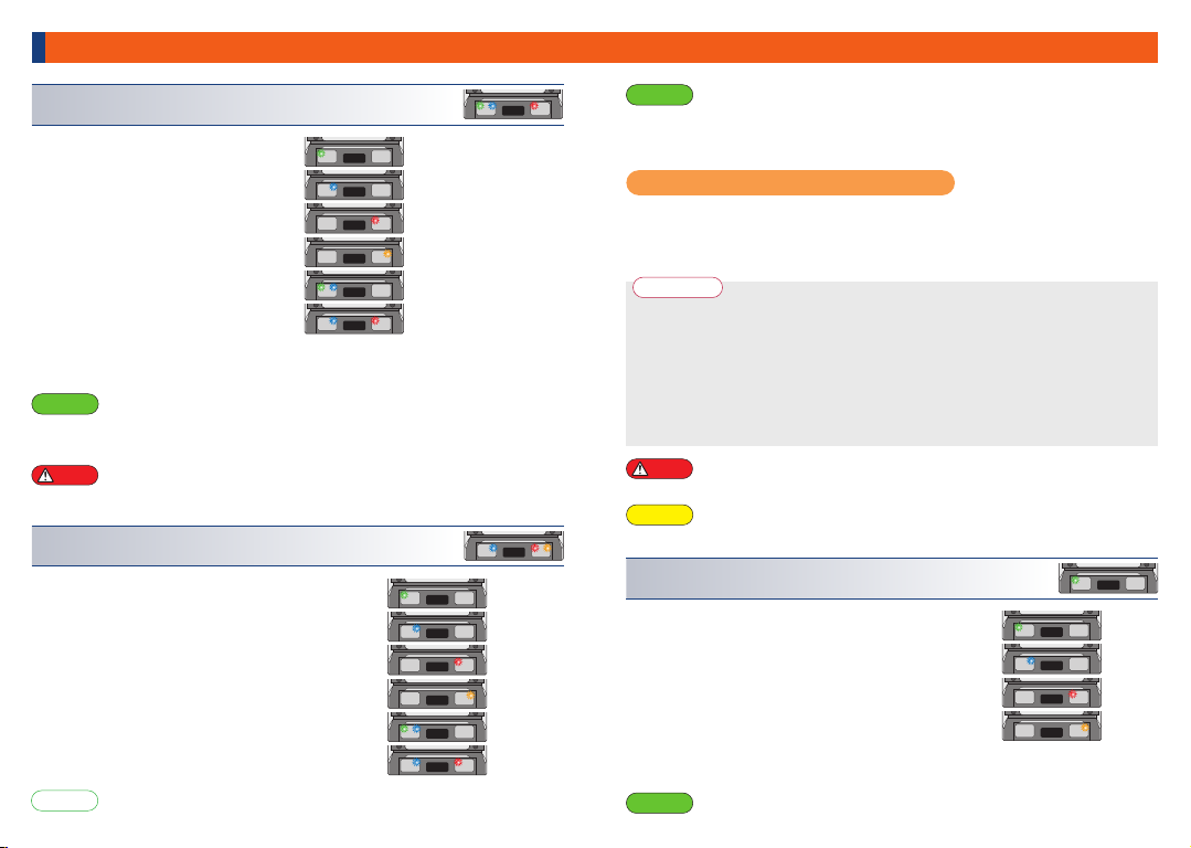
Commentary
⑨
In the select mode with the
green+blue+red LED flashing twice,
press the SET button for 2 seconds or
more to enter the setting mode. Each
time the SET button is pressed once,
the LED pattern changes and the
operating mode changes as shown on
the right. Adjust the LED to the setting of
your choice and press the SET button
for 2 seconds or more. The set value is
validated and it returns to select mode.
The changed value will be reset if the
power is turned off without saving.
Please save your settings before tunring
your unit off (P.20).
Switched between normal and reverse motor rotation. Regardless of whether the
initial settings have been completed properly, the car may go into reverse once the
throttle is applied. If this condition occurs, please use Reverse rotation operation
mode. The orange LED will be lit in standby mode when Reverse rotation is
selected.
Commentary
⑩
In the select mode with the blue+red+orange LED
flashing twice, press the SET button for 2 seconds
or more to enter the setting mode. Each time the
SET button is pressed once, the LED pattern
changes and the cutoff voltage value changes as
shown on the right. Adjust the LED to the setting of
your choice and press the SET button for 2
seconds or more. The set value is validated and it
returns to select mode. The changed value will be
reset if the power is turned off without saving.
Please save your settings before tunring your unit
off (P.20).
It is a function to notify the driver of low voltage condition before the unit reaches
critical voltage and performance decrease. When the voltage reaches the cutoff
voltage while driving, the green LED will flash and the vehicle will travel very
slowly. When disabled is selected, this function will not work. Please be careful
about your runtime and other conditions.
Commentary
⑪
Operation mode (grn+blu+red flashing twice)
Cutoff voltage (blu+red+org flashing twice)
Full boost timing (green flashing 4 times)
In the select mode with the green LED flashing 4 times,
press the SET button for 2 seconds or more to enter
the setting mode. Each time the SET button is pressed
once, the LED pattern changes and the boost timing
value changes as shown on the right. Adjust the LED
to the setting of your choice and press the SET button
for 2 seconds or more. The set value is validated and it
returns to select mode. The changed value will be
reset if the power is turned off without saving. Please
save your settings before tunring your unit off (P.20).
This determines the maximum value (terminal value) for timing increased through
boost.
Disabled
2.8V/Cell
3.0V/Cell
3.1V/Cell
3.2V/Cell
3.4V/Cell
0deg
15deg
25deg
45deg
Because the number of cell is automatically recognized, select the voltage per cell.
If set to disabled, pay close attention to your runtime.
Reference
About Boost / Turbo Function
Forward rotation
Forward+Brake
Forward rotation
Forward+Brake+Reverse
Forward rotation
Forward+Brake (for crawlers)
Forward rotation
Forward+Brake
Forward rotation
Forward+Brake+Reverse
Forward rotation
Forward+Brake (for crawlers)
Warning
Warning
18 19
TUNING THE DRIVING EXPERIENCE
Commentary
This determines the motor rpm at which the boost will begin to operate. As this rpm
value is set lower, boost will operate from a lower speed/rpm point.
⑫
In the select mode with the blue LED flashing 4
times, press the SET button for 2 seconds or more
to enter the setting mode. Each time the SET
button is pressed once, the LED pattern changes
and the boost start rpm value changes as shown
on the right. Adjust the LED to the setting of your
choice and press the SET button for 2 seconds or
more. The set value is validated and it returns to
select mode. The changed value will be reset if the
power is turned off without saving. Please save
your settings before tunring your unit off (P.20).
5,000rpm
10,000rpm
15,000rpm
20,000rpm
Caution When set low, it is necessary to lighten the drive load and adjust your gear ratio.
Commentary
This determines the motor rpm at which the boost will end. As this rpm value is set
higher, boost will operate to a higher speed/rpm point.
⑬
In the select mode with the red LED flashing 4
times, press the SET button for 2 seconds or more
to enter the setting mode. Each time the SET
button is pressed once, the LED pattern changes
and the boost end rpm value changes as shown
on the right. Adjust the LED to the setting of your
choice and press the SET button for 2 seconds or
more. The set value is validated and it returns to
select mode. The changed value will be reset if the
power is turned off without saving. Please save
your settings before tunring your unit off (P.20).
15,000rpm
20,000rpm
30,000rpm
40,000rpm
50,000rpm
Caution Please make sure to set the boost end rpm higher than the value of your boost
start rpm. The sudden jump in timing may overload the ESC, therefore it is advised
to start with a much higher boost end rpm and progressively lower timing as you
get comfortable with your gearing.
Commentary
This determines the amount of turbo timing added at full throttle.
⑭
In the select mode with the green+red LED
flashing 4 times, press the SET button for 2
seconds or more to enter the setting mode. Each
time the SET button is pressed once, the LED
pattern changes and the full turbo timing value
changes as shown on the right. Adjust the LED to
the setting of your choice and press the SET
button for 2 seconds or more. The set value is
validated and it returns to select mode. The
changed value will be reset if the power is turned
off without saving. Please save your settings
before tunring your unit off (P.20).
0deg
12deg
20deg
30deg
Important
When using both boost and turbo function at the same time, make sure the total
value of full boost timing and full turbo timing are less than 60°
Commentary
This function limits the output of the motor so that the rpm does not exceed the set
value.
⑮
Boost start rpm (blue flashing 4 times)
Boost end rpm (red flashing 4 times)
Full turbo timing (green+red flashing 4 times)
Rev-Limiter rpm (blu+red+org flashing 4 times)
In the select mode with the blue+red+orange LED
flashing 4 times, press the SET button for 2
seconds or more to enter the setting mode. Each
time the SET button is pressed once, the LED
pattern changes and the rev-limiter rpm value
changes as shown on the right. Adjust the LED to
the setting of your choice and press the SET
button for 2 seconds or more. The set value is
validated and it returns to select mode. The
changed value will be reset if the power is turned
off without saving. Please save your settings
before tunring your unit off (P.20).
OFF
15,000rpm
30,000rpm
50,000rpm
20 21
TUNING THE DRIVING EXPERIENCE Error signal during driving (LED flashing pattern)
When shipped from the factory, the unit is preset with the [Drift] program (see the
table above for the setting values of each item). Please change each set of value
according to your preference (For changing method, see P.10 to P.19).
About the factory preset program
In SELECT mode, pressing the SET button 4 times
quickly causes all LEDs to flash, and then automatically
switches to the display that selects the save destination of
the user program. The green LED is the user program ①,
the orange LED is the user program ②. Each time you
press the SET button, the save destination is switched.
After selecting the save destination, press the SET button
for 2 seconds or more to save it and return to the standby
mode.
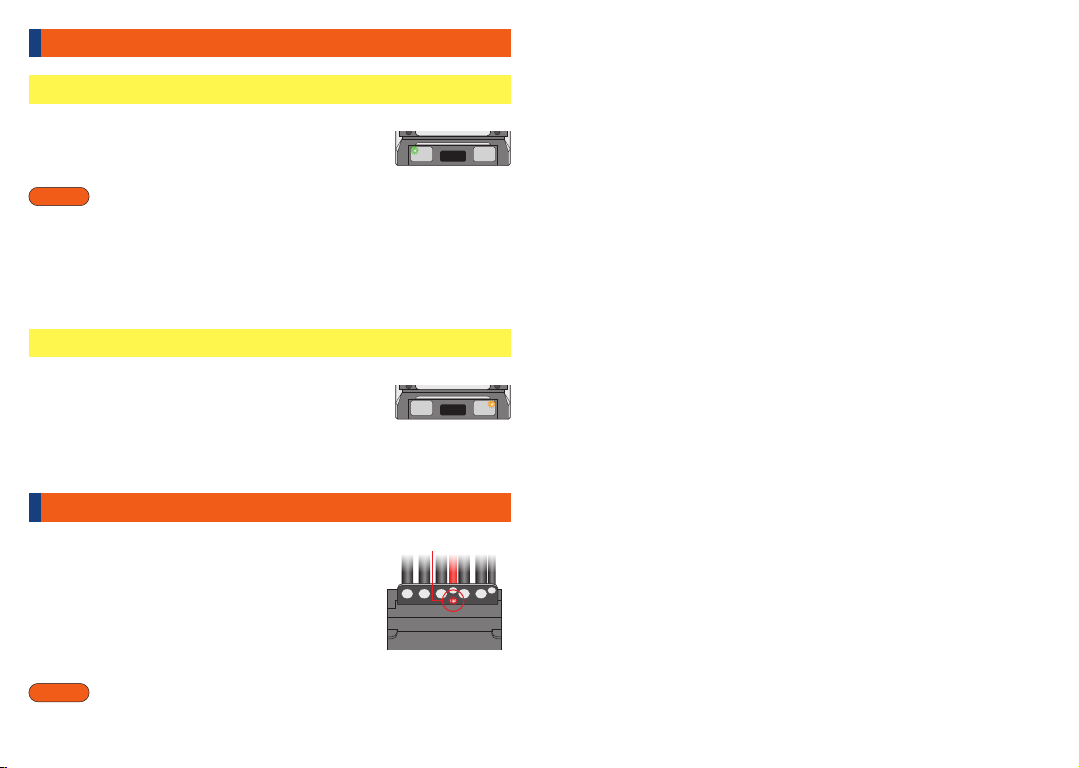
Switching of BEC output voltage
In standby mode, press and hold the POWER button and
SET button simultaneously for about 2 seconds.
The green LED status changes to OFF or ON, and the BEC
output voltage changes.
Regardless of the setting mode, the BEC output voltage can be switched using
this procedure.
Press the SET button
Quickly 4 times
Saving user program (current value)
Commentary
The saved user programs can be called up by the program load function mentioned
earlier.
press and hold
All LEDs blinking
[LED green is OFF during standby] BEC output voltage 6.0V
[LED green is ON during standby] BEC output voltage 7.4V
When the sensor signal is interrupted or becomes unstable
for some reason, the motor stops with all the LEDs blinking.
When all the LEDs are blinking, no button operation is
accepted, so remove the battery and turn off the power.
Below is a summary of the LED signal pattern that occurs when something
abnormal is detected while driving.
Refer to P.8 to P.9 “Checking standby status” for the LED lighting / flashing
pattern in standby mode.
Motor stops with all LEDs blinking 〜 Sensor error
[Possible cause of signal generation]
・An error has occurred in the motor sensor.
・Sensor cable has poor contact
・The sensor cable is affected by radiation noise from the motor cable and
the sensor signal is disturbed.
[Workaround]
・Replacing the motor sensor
・Replacing the sensor cable
・Install the sensor cable and motor cable as far apart as possible
※Disturbance of the sensor signal may cause abnormal heat generation and
damage to the ESC and motor. Do not bundle the sensor cable with the motor
connection cable. Install them as far apart as possible.
MEMO
C B A + -
Error signal during driving (LED flashing pattern)
When the ESC battery terminal voltage drops to the cut-off
voltage set on P.16, the standby LED lights up and flashes,
and the green LED will be flashed and drive speed is going
to low.
LED green blinks and runs at low speed ~ Low voltage cut-off
Protection circuit for Battery reverse connection
This product is equipped with a reverse battery protection
circuit, so the ESC circuit is protected if the reverse
connection less than about 10 seconds. (Some heat is
generated when the protection circuit is activated.)
When the battery is connected in reverse, the LED on the
back of the battery terminal will turn red. Remove the
battery immediately and reconnect it correctly.
※The protection circuit is automatically activated
when the battery is reversely connected.
When the ESC overheats due to driving and reaches the
specified temperature, the orange LED blinks in addition to
the standby LED lighting / flashing, and the vehicle runs at
low speed.
In this case, stop driving until the ESC temperature drops.
If the heat protection is activated in a short driving time, the gear ratio setting may be
overloaded. In this case, check each setting status.
LED orange blinks and runs at low speed 〜 Heat protection
22 23
Important
The condition to detect the cut-off voltage is not “Battery voltage” but “ESC battery
terminal voltage”. If the contact condition of the connector to which the battery is
connected and the welded state of the solder bonding the connector are
insufficient, that portion will have a large electrical resistance, and the voltage
detected at the ESC terminal will be far below the battery voltage.
If there is a large difference between the set cut-off voltage and the actual battery
voltage at the time of cut-off operation, the reason may be due to the connector to
which the battery is connected or the solder welding location of the connector.
In such cases, the ESC or motor performance may not be fully achieved. It is
recommended to replace the connector or rework the solder.
Important
This function protects only the ESC circuit board when the battery is reversely
connected. Capacitors connected to ESC such as Chevalier series are not
protected, so be careful when connecting batteries.
Green LED blinking
Orange LED blinking
Alert red LED light
Table of contents
Popular Motorized Toy Car manuals by other brands


INJUSA
INJUSA Porsche 911 Turbo S user manual

Fisher-Price
Fisher-Price X6023 instruction sheet

Team Losi
Team Losi XXX-T Matt Francis Edition owner's manual

Fast Lane
Fast Lane XPS AD17270 X-6 NIGHTCRAWLER instruction manual

Schumacher Racing
Schumacher Racing Eclipse instruction manual

Team Losi
Team Losi LST 3XL-E RTR instruction manual