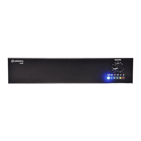
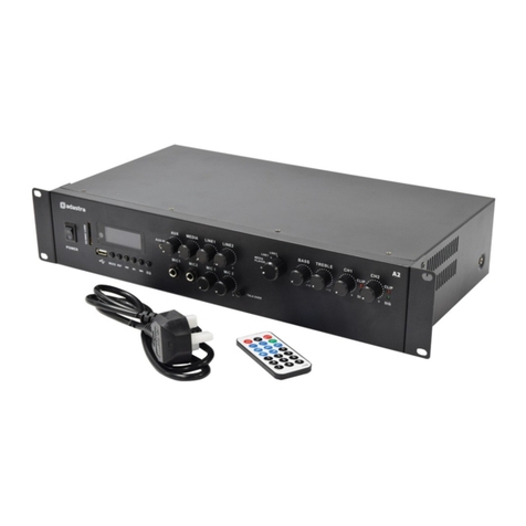
Adastra 952.993 User manual

Series 900
Operation Manual
MODEL: 952.993 - 240W SLAVE AMPLIFIER
Output Rated. . . . . . . . . . . . . . . . . . . . . . . . . . . . . . . . . . . . 240W
10% THD. . . . . . . . . . . . . . . . . . . . . . . . . . . . . . . . . . 290W
Output regulation. . . . . . . . . . . . . . . . . . . . . . . . . . . < 2dB, no load to full load.
Slave output ( mono). . . . . . . . . . . . . . . . . . . . . . . . . . . . . . 600 ohm, 1V ( 0dB )
Slave input sensitivity . . . . . . . . . . . . . . . . . . 300mV ( - 10.4dBV ), unbalanced.
Input impedance. . . . . . . . . . . . . . . . . . . . . . . . . . . . . . . . . . . . . . . . . . . . . . . . 10K
Input connector . . . . . . . . . . . . . . . . . . . . . . . . . . . . . . . . . . . . RCA phono socket
Loudspeaker connector. . . . . . . . . . . . . . . . . . . . . . . . . . . . . . . . . Terminal block.
Frequency response . . . . . . . . . . . . . . . . . . . . . . . . . . . . 100Hz – 10kHz +/- 3dB
Distortion. . . . . . . . . . . . . . . . . . . . . . . . . . . . . . . < 2% @ 1kHz on rated power
Protection circuits . . . . . . . . . . . . . . . . . . . .Current limit, thermal, AC/DC fuses
Power AC Mains . . . . . . . . . . . . . . . . . . . 230V ac, 50 Hz, 600W
Battery . . . . . . . . . . . . . . . . . . . . . . . . . . . . . 24V dc 16A
DC performance Volt . . . . . . . . . . . . . . . . . . . . . . . . . . . . . . . . . . . . . 26.4V
Current . . . . . . . . . . . . . . . . . . . . . . . . . . . . . . . . . . . . 12A
Pout. . . . . . . . . . . . . . . . . . . . . . . . . . . . . . . . . . . . . 170W
Dimensions( W x H x D ) . . . . . . . . . . . . . . . . . . . . . . . . . . . 482 x 88 x 290 mm
Weight . . . . . . . . . . . . . . . . . . . . . . . . . . . . . . . . . . . . . . . . . . . . . . . . . . . . . . 10Kg.
952.993 SLAVE AMPLIFIER 240W
952.993 SLAVE AMPLIFIER 240W


The Adastra 953.993 is a high power slave amplifier designed to compliment the 900
series of mixer amplifiers or any other suitable source.
Provision is made for connection to either 100V line or low impedance loudspeakers.
The amplifier can operate from a 230volt AC or 24V dc power source.
LOUDSPEAKERS
All connections to the loudspeaker terminals should be made using suitable spade
connectors crimped or soldered to the speaker cables. Any other method can give rise to
short circuits. There is provision for both 100 volt line and low impedance loudspeakers,
but both types must NOT be used on the same installation.
Low impedance loudspeakers should be connected in a series parallel arrangement such
that the load always equals 8 ohms eg. Four 8 ohm speakers can be connected in such
an arrangement and connected across the common and 8 ohm terminals. Care should
be taken with this set up in that the volume level is carefully controlled, as it is possible
to damage loudspeakers by using too high a volume setting.
100V line should be connected to the common and 100V line terminal, taking care that
the sum of the wattage of all the loudspeakers on the line does not exceed the total
power available from the amplifier. NOTE: It is good practice to allow a headroom of 10%
when doing calculations.
Please Note. All the loudspeaker terminals are fully floating with respect to chassis. In the
event of cross talk to other services or instability then in certain circumstances the “COM
“ terminal may require strapping to the earth binding post.
Remember that a low impedance system requires heavy cable feeding the loudspeakers
to minimise losses. For a widespread installation ( ie. a factory system ) it is far better to
use a 100V line system. See ADASTRAGEN sheet No. 5 for more information.
INPUT / OUTPUT CONNECTIONS
RCA phono sockets are located on the rear panel.
Connect signal from the mixer amplifier to the SLAVE IN sockets. These are connected
internally to provide a mono input. The slave out is used for connection to additional
slave amplifiers
BATTERY OPERATION
A 24 volt battery should be connected using suitable spade terminals crimped to the
battery cables and secure connection made. Observe the correct polarity.
NOTE. The power switch does not control the 24 volt supply to the amplifier. If battery
ON/ OFF control is required then a separate switch will need to be fitted remote to the
amplifier. The power output will be reduced with battery operation and output is also
dependent on the condition of the battery.
SETTING UP
When all connections have been made, check the MASTER control is at zero, then plug
the IEC mains lead into the socket on the rear panel of the amplifier and the 13A plug
into a suitable 230V ac socket.
Depress the power ON/OFF switch and the POWER LED will illuminate. Advance the
MASTER control and observe the SIGNAL LED, as the volume is increased the LED will
start to flash, indicating a signal is being transmitted to the loudspeakers. The control
should be set such that the peaks of sound keep the SIGNAL indicator almost continuously
lit, with the PEAK indicator only showing a few times or not at all. Continuous illumination
of the PEAK LED indicates the amplifier is being over loaded.
INTERFERENCE
Whilst this unit complies in all aspects with EMC legislation its use in an industrial
environment, where there are many potential sources of interference, means that steps
may need to be taken to minimise any difficulties.
ALWAYS check that the amplifier has a good earth. In the event of interference secure the
services of a qualified electrician to carry out tests on the mains socket used to ensure
a low resistance path exists.
Do not site the amplifier adjacent to large transformers, TV monitors and computers.
OPERATION MANUAL - ADASTRA 900 SERIES GB
WARNING: DO NOT CONNECT THE MAINS SUPPLY TO THE AMPLIFIER UNTIL ALL
THE NECESSARYINPUT AND OUTPUT CONNECTIONS HAVE BEEN MADE.
WARNING: THIS APPLIANCE MUST BE EARTHED
WARNING: SHOCK HAZARD - DO NOT OPEN
AVIS: RISQUE DE CHOC ELECTRIQUE - NE PAS OUVRIR
CAUTION
RISK OF ELECTRIC SHOCK
DO NOT OPEN
952.993 SLAVE AMPLIFIER 240W
952.993 SLAVE AMPLIFIER 240W
952.993 SLAVE AMPLIFIER 240W
1. Master rotary volume control
2. Power, Signal and Peak LED indicators
3. Power ON/OFF switch.
4. IEC fused mains input socket
5. Ground terminal
6. DC input terminal
7. Loudspeaker terminal (8Ω & 100V)
8. Slave Input / output RCA phono sockets.
1
2
3
4
567
8
Sleeve - Screen
Pin - Signal
2 1
3
PUSH
SLEEVE RING TIP
SLEEVE PIN

De adastra 953.933 is een krachtige slave versterker, ontworpen om de 900 serie
mixversterkers of andere geschikte apparatuur te ondersteunen.
Dit apparaat kan zowel aangesloten worden met 100 V apparatuur als luidsprekers met
lage impedantie en werkt zowel op 230 VAC als op 24 VDC aansluitspanning.
LUIDSPREKERS
Bij alle verbindingen met de luidspreker ingangen dient gebruik te worden gemaakt van
geschikte terminals die op de juiste manier bevestigd zijn met de luidsprekerkabel. Als
hiervan wordt afgeweken kan er kortsluiting optreden. Er is een mogelijkheid om 100V
apparatuur aan te sluiten, maar verbind nooit beide types (8 Ohm & 100V) tegelijk met
de versterker.
Lage impedantie luidsprekers dienen parallel verbonden te worden. Dit om ervoor
te zorgen dat de maximale belasting altijd 8 Ohm bedraagt Bijvoorbeeld: vier 8 Ohm
luidsprekers kunnen op deze manier verbonden worden, zowel met de “com” als de
“8 Ohm” uitgangen, genoemd in het figuur bij 7. Let bij een dergelijke installatie wel
op dat het volumeniveau met behoud word geregeld en dat het volume niet te hoog
wordt ingeschakeld. Als dit niet gebeurt, kunt u de luidspreker(s) overbelasten en
beschadigen.
Een 100 V verbinding dient gemaakt te worden met de “com” & “100 V” uitgangen,
genoemd in het figuur bij 7. Let hierbij wel op, dat het opgetelde vermogen van de
luidsprekers het vermogen van de versterker niet overschrijd Het is hierbij aan te raden
om maximaal 10% minder vermogen aan te sluiten dan dat de versterker aan kan.
Let op. Alle luidsprekerterminals zijn volledig geïsoleerd t.o.v. de behuizing. In geval
van overspraak of instabiliteit van de installatie kunt u de “com” (7) doorverbinden met
de aarde aansluiting (5). Bij een lage impedantie systeem is heavy duty bekabeling
noodzakelijk om verliezen te minimaliseren. Bij een uitgebreide installatie is het
verstandiger gebruik te maken van een specifiek 100 V lijnsysteem.
IN- & UITGANGEN
De RCA (tulp) in- & uitgangen bevinden zich op de achterzijde van het apparaat (8).
Verbind het signaal van de mixversterker met de “SLAVE IN” ingang. Deze zijn intern
doorverbonden om een mono ingangssignaal te leveren. De “SLAVE OUT” wordt
gebruikt om een verbinding te maken met eventuele extra slave versterkers.
ACCU AANSLUITING
Een 24 VDC spanningsbron dient verbonden te worden met geschikte connectoren die
aan de kabel zijn geklemd of gesoldeerd. Sluit een spanningsbron die 24 VDC levert
aan op de “24 VDC” ingang (6). Let op de juiste polariteit bij het aansluiten.
LET OP. Met de Aan/Uit schakelaar (3) kunt u de 24 VDC spanningsbron NIET bedienen.
Als u deze functie wel wenst, dient er een aparte schakelaar tussen de 24 VDC
spanningsbron en de versterker geïnstalleerd te worden. Het uitgangssignaal is van
mindere kwaliteit met een accu aansluiting en deze hangt ook af van de conditie van
de verbonden accu.
OPSTELLEN
Zodra alle verbindingen zijn gelegd en alle regelaars op minimaal zijn ingesteld, kunt u
de meegeleverde stroomkabel gebruiken voor het leggen van een verbinding met een
geschikt geaard stopcontact. Na het indrukken van de aan / uitschakelaar (3) zal de
LED spanningsindicator oplichten.
Regel de master volume bediening (1) en kijk naar het signal LED. Met het toenemen
van het volume zal deze LED gaan knipperen, wat betekend dat het uitgangssignaal
naar de aangesloten luidsprekers wordt verzonden. Bij de beste volume-instelling licht
de signal LED bijna constant op, terwijl de peak LED af en toe of helemaal niet oplicht.
Als de peak LED continu oplicht, betekent dit dat de versterker overbelast word. Regel
het volume dan meteen omlaag!
INTERFERENTIE
Hoewel dit apparaat volledig is goedgekeurd onder de EMC regelgeving voor industrieel
gebruik, is het mogelijk dat er bronnen zijn die interferentie veroorzaken. Om de
problemen te minimaliseren kunt u de volgende stappen doorlopen. Controleer of de
versterker goed is geaard. Laat een gekwalificeerd persoon een controle uitvoeren om
zeker te zijn van een lage weerstand op de aarding. Plaats de versterker niet in de
buurt van grote transformatoren, TV’s en computers.
GEBRUIKSAANWIJZING – ADASTRA 900 SERIE NL
WAARSCHUWING: VERBIND PAS MET STOPCONTACT ALS ALLE
BENODIGDE IN- EN UITGANGEN AANGESLOTEN ZIJN
WAARSCHUWING: DIT APPARAAT DIENT GEAARD TE WORDEN
WARNING: SHOCK HAZARD - DO NOT OPEN
PAS OP: KANS OP ELEKTRISCHE SCHOK – OPEN DE BEHUIZING NIET!
AVIS: RISQUE DE CHOC ELECTRIQUE - NE PAS OUVRIR
CAUTION
RISK OF ELECTRIC SHOCK
DO NOT OPEN
952.993 SLAVE AMPLIFIER 240W
952.993 SLAVE AMPLIFIER 240W
952.993 SLAVE AMPLIFIER 240W
1. Mastervolume draaibediening
2. Aan/Uit, signaal en piek LED indicators
3. Aan/Uit schakelaar
4. Gezekerde 230VAC ingang
5. Aarde terminal
6. VDC ingang
7. Luidsprekeraansluiting (8 Ohm, 100 V)
8. Slave RCA (tulp) ingang / uitgang
1
2
3
4
567
8
Huls – Afscherming
Pin – Signaal
2 1
3
PUSH
SLEEVE RING TIP
SLEEVE PIN

L’amplificateur esclave Adastra 952.993 de haute puissance est conçu pour compléter
la série 900 d’amplificateurs de mixage ou tout autre source appropriée.
Il accepte des haut-parleurs de ligne 100V ou basse impédance et peut être alimenté
en 230Vac ou 24Vdc.
ENCEINTES
Toutes les connexions aux bornes de haut-parleurs doivent être effectuées par des
cosses à sertir ou à souder sur les câbles de haut-parleurs. Toute autre méthode présente
un risque de court-circuit. Des connecteurs sont prévus pour des enceintes à ligne 100V
et basse impédance. Cependant il ne faut JAMAIS utiliser les deux types sur la même
installation.
Les enceintes basse impédance devront être connectées dans un schéma série/parallèle
de façon à ce que la charge soit toujours égale à 8 Ω. P.ex. quatre haut-parleurs 8Ω
peuvent être connectés de cette façon et branchés en parallèle à la fiche commune et
aux borniers 8Ω. Dans cette configuration, il faut surveiller de très près le niveau de
volume parce que les haut-parleurs risquent d’être endommagés si le niveau est trop
élevé.
Branhcez les haut-parleurs 100V sur les borniers commun et ligne 100V en veillant
à ce que la somme de la puissance de tous les haut-parleur sur la ligne ne dépasse
pas la puissance totale de l’amplificateur. Note: Il est d’usage de laisser une marge de
manoeuvre de 10% dans les calculs.
Notez que tous les borniers de haut-parleurs sont isolés de la masse du châssis. En cas
de perturbations ou d’instabilité, il peut être nécessaire de relier le bornier ‘COM’ à la
borne de masse.
Un système basse impédance nécessite de gros câbles vers les haut-parleurs pour
minimiser les pertes. Pour une installation large (p.ex. dans une usine), il est recommandé
d’utiliser un système 100V.
CONNEXIONS D’ENTREE / DE SORTIE
Les fiches RCA se trouvent à l’arrière. Connectez le signal de l’amplfiicateur aux fiches
SLAVE IN qui sont connectées en interne pour constituer une entrée mono. La sortie
esclave est utilisée pour le branchement sur d’autres amplificateurs esclaves.
ALIMENTATION PAR BATTERIE
Branchez une batterie 24Vdc au moyen de câbles équipés de cosses à sertir qui sont
fermement connectés en respectant la bonne polarité.
NOTE. L’interrupteur M/A ne fonctionne pas avec une alimentation 24Vdc. Si vous avez
besoin d’un interrupteur M/A pour le fonctionnement par batterie, il faudra installer un
commutateur à part. La puissance de l’amplificateur diminue en cas d’alimentation par
batterie. La sortie dépend également de l’état de la batterie.
MISE EN SERVICE
Lorsque toutes les connexions ont été effectuées, vérifiez que le contrôle MASTER se
trouve sur Zéro. Branchez le cordon secteur sur la fiche IEC au dos de l’amplificateur
ainsi que dans une prise secteur appropriée.
Appuyez sur l’interrupteur ON/OFF et le voyant ‘POWER’ s’allumera. Avancez le contrôle
MASTER et observez le voyant SIGNAL. Lorsque le volume augmente, le voyant va
commencer à clignoter, indiquant que le signal est transmis aux enceintes. Le contrôle
doit être réglé de telle manière que l’indicateur SIGNAL reste pratiquement toujours
allumé et l’indicateur PEAK ne s’allume que très peu ou pas du tout. Si le voyant PEAK
reste allumé en permanence, l’amplificateur est surchargé.
INTERFERENCES
Bien que cet appareil soit en tous points conforme au règlement CEM, il peut être
nécessaire dans un environnement industriel en présence de nombreuses sources
potentielles d’interférences, de prendre certaines mesures afin de minimiser les
difficultés éventuelles.
Vérifiez TOUJOURS la connexion à la terre. En cas d’interférences, un électricien qualifié
doit effectuer des tests sur la prise secteur pour s’assurer de la présence d’un chemin
de basse résistance.
Ne pas placer l’amplificateur à proximité de grands transformateurs, moniteurs TV et
ordinateurs.
MODE D’EMPLOI - ADASTRA SERIE 900 F
ATTENTION: NE PAS BRANCHER L’AMPLIFICATEUR SUR LE SECTEUR AVANT
D’AVOIR EFFECTUE TOUTES LES CONNEXIONS D’ENTREE ET DE SORTIE
ATTENTION: CET APPAREIL DOIT ETRE BRANCHE SUR LA TERRE
WARNING: SHOCK HAZARD - DO NOT OPEN
RISQUE DE CHOC ELECTRIQUE - NE PAS OUVRIR
CAUTION
RISK OF ELECTRIC SHOCK
DO NOT OPEN
952.993 SLAVE AMPLIFIER 240W
952.993 SLAVE AMPLIFIER 240W
952.993 SLAVE AMPLIFIER 240W
1. Contrôle de volume général
2. Voyants de tension, de signal et de crête
3. Interrupteur M/A.
4. Fiche IEC d’alimentation secteur avec fusible
5. Borne de masse
6. Fiche d’alimentation DC
7. Bornier haut-parleur (8Ω & 100V)
8. Fiches RCA d’entrée/sortie esclave
1
2
3
4
567
8
Gaine - Blindage
Broche - Signal
2 1
3
PUSH
SLEEVE RING TIP
SLEEVE PIN

Dieser Hochleistungsnebenverstärker 952.993 von Adastra vervollständigt die 900er
Serie von Mischverstärkern oder andere geeignete Geräte.
Der Verstärker kann entweder an eine 100V Line oder niederohmige Lautsprecher
angeschlossen werden. Er wird von 230V AC Netzstrom oder 24V DC Batteriestrom
gespeist.
LAUTSPRECHER
Alle Anschlüsse an die Lautsprecherklemmen müssen über geeignete Flachsteckverbinder
erfolgen, die an die Lautsprecherkabel gekrimpt oder gelötet werden. Jede andere
Methode kann zu Kurzschlüssen führen. Es sind Anschlüsse sowohl für 100V Line als
auch niederohmige Lautsprecher vorhanden. Diese beiden Typen dürfen jedoch NICHT
zusammen in derselben Anlage verwendet werden.
Niederohmige Lautsprecher müssen in einer Serie/parallel Konfiguration angeschlossen
werden, so dass die Last immer 8Ω entspricht. Vier 8Ω Lautsprecher können auf diese
Weise angeschlossen und parallel an die gemeinsame (COM) und die 8Ω Klemmen
angeschlossen werden. Hierbei muss der Lautsprecherpegel sorgfältig geprüft werden,
da die Lautsprecher durch eine zu grosse Lautstärke beschädigt werden können.
100V Line Lautsprecher müssen an die gemeinsame (COM) und die 100V Line Klemme
angeschlossen werden, wobei die Leistungssumme aller Lautsprecher die gesamte Watt-
zahl des Verstärkers nicht übersteigen darf. Hinweis: Es ist ratsam, bei der Berechnung
immer einen Spielraum von 10% zu lassen.
Hinweis: Alle Lautsprecherklemmen sind von der Masse isoliert. Falls Störungen
auftreten, müssen die “COM” Klemmen an eine Masseschraube angeschlossen werden.
Beachten Sie bitte, dass niederohmige Anlagen starke Lautsprecherkabel benötigen,
um Verluste zu verringern. Für weiträumige Anlagen (z.B. in einer Fabrik) ist es weitaus
besser, ein 100V Line System zu benutzen.
EIN- UND AUSGANGSVERBINDUNGEN
Die Cinch Buchsen befinden sich auf der Rückseite.
Schliessen Sie das Signal vom Mischverstärker an die SLAVE IN Buchsen an. Diese sind
intern miteinander verbunden, und bilden einen Mono-Eingang. Die SLAVE OUT Buchse
ist zum Anschluss von zusätzlichen Nebenverstärkern vorgesehen.
BATTERIEBETRIEB
Eine 24V Batterie muss mit geeigneten Flachsteckverbindern an die Batteriekabel
gekrimpt und sicher angeschlossen werden. Bitte beachten Sie die richtige Polung.
HINWEIS: Der Ein/Aus Schalter hat keinen Einfluss auf die 24V Speisung zum Verstärker.
Wenn eine separate EIN/AUS Schaltung bei Batteriebetrieb benötigt wird, muss ein
separater Schalter angebracht werden. Bei Batteriespeisung ist die Ausgangsleistung
geringer und hängt zudem vom Zustand der Batterie ab.
INBETRIEBNAHME
Wenn alle Anschlüsse durchgeführt worden sind, prüfen Sie, ob der MASTER Regler auf
Null steht. Stecken Sie das Netzkabel in die Buchse auf der Rückseite des Verstärkers
und in eine geerdete 230V AC Netzsteckdose.
Drücken Sie auf den ON/OFF Schalter. Die Betriebsanzeige leuchtet auf. Drehen Sie den
MASTER Regler langsam hoch und beobachten Sie die SIGNAL Anzeige. Bei steigender
Lautstärke beginnt die Anzeige zu blinken. Dies bedeutet, dass den Lautsprechern
ein Signal zugeführt wird. Der Regler muss so eingestellt werden, dass die Signalanzeige
bei Musikspitzen fast ständig leuchtet, während die PEAK Anzeige kaum bzw. gar nicht
aufleuchten darf. Ein ständiges Leuchten der PEAK Anzeige bedeutet, dass der Verstärker
überlastet ist.
STÖRUNGEN
Das Gerät entspricht den geltenden EMC Bestimmmungen. Der Einsatz in industrieller
Umgebung, wo zahlreiche Störquellen vorhanden sein können, kann die Ergreifung
bestimmter Massnahmen erfordern.
Prüfen Sie IMMER den Erdanschluss des Verstärkers. Falls Störungen auftreten sollten,
ziehen Sie einen qualifizierten Elektriker zu Rate, um die nötigen Tests an der Steckdose
durchzuführen.
Den Verstärker nicht in der Nähe von grossen Trafos, TV Bildschirmen und Computern
aufstellen.
BEDIENUNGSANLEITUNG - ADASTRA 900 SERIE D
WARNUNG: ERST ALLE EIN- UND AUSGÄNGE ANSCHLIESSEN, BEVOR SIE DAS
GERÄT ANS NETZ ANSCHLIESSEN.
WARNUNG: DIESES GERÄT MUSS GEERDET SEIN
WARNING: SHOCK HAZARD - DO NOT OPEN
ACHTUNG: STROMSCHLAGGEFAHR - NICHT ÖFFNEN
VORSICHT
STROMSCHLAGGEFAHR
NICHT ÖFFNEN
952.993 SLAVE AMPLIFIER 240W
952.993 SLAVE AMPLIFIER 240W
952.993 SLAVE AMPLIFIER 240W
1. Master Lautstärkeregler
2. Betrieb-, Signal- und Spitzenanzeiger
3. Ein/Aus Schalter
4. Gesicherte IEC Netzbuchse
5. Masseanschluss
6. DC Eingangsklemmverbinder
7. Lautsprecherklemmverbinder (8Ω & 100V)
8. Cinch Buchsen für den Nebenverstärkerein-/ausgang.
1
2
3
4
567
8
Hülse - Abschirmung
Stift - Signal
2 1
3
PUSH
SLEEVE RING TIP
SLEEVE PIN


www.skytronic.com
Table of contents
Languages:
Other Adastra Amplifier manuals
Adastra
Adastra A4-PLUS User manual
Adastra
Adastra RM4460 User manual
Adastra
Adastra DM40 User manual
Adastra
Adastra RM306 User manual

Adastra
Adastra RM244V User manual
Adastra
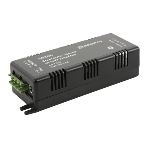
Adastra IW30B User manual
Adastra
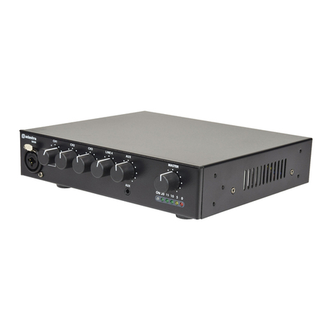
Adastra UA Series User manual
Adastra
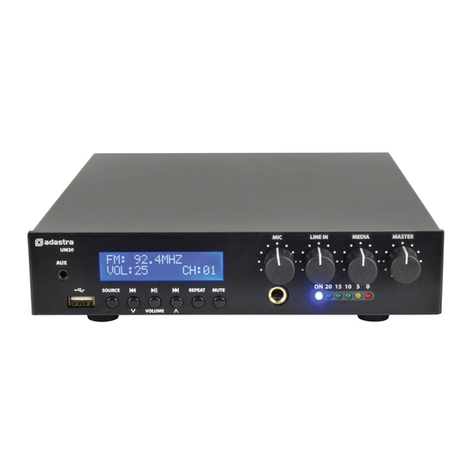
Adastra UM60 User manual
Adastra
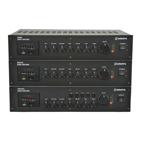
Adastra RM60 User manual
Adastra
Adastra 952.996 User manual
Adastra
Adastra 952.931 User manual
Adastra
Adastra 952.916 User manual
Adastra
Adastra A Series User manual
Adastra
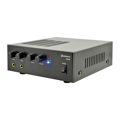
Adastra CA30 User manual
Adastra
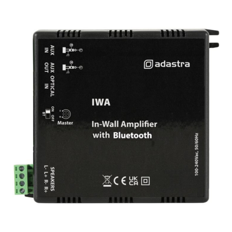
Adastra IWA Series User manual
Adastra
Adastra RMD Series User manual
Adastra
Adastra RMS1202 User manual

Adastra
Adastra A200 User manual
Adastra
Adastra LA-75 User manual
Adastra
Adastra CM30 User manual

