ADB Safegate FLA User manual
Airfield Lighting Field Lightning Arrestor
User Manual
96A0489, Rev. B, 2018/03/06

A.0 Disclaimer / Standard Warranty
CE certification
The equipment listed as CE certified means that the product complies with the essential requirements concerning safety and
hygiene. The directives that have been taken into consideration in the design are available on written request to ADB
SAFEGATE.
ETL certification
The equipment listed as ETL certified means that the product complies with the essential requirements concerning safety and
FAA Airfield regulations. The directives that have been taken into consideration in the design are available on written request
to ADB SAFEGATE.
LED Product Guarantee
Where applicable, per FAA EB67(applicable edition), ADB SAFEGATE L858(L) Airfield Guidance Signs are warranted against
electrical defects in design or manufacture of the LED or LED specific circuitry for a period of 4 years. ADB SAFEGATE LED light
fixtures (with the exception of obstruction lighting) are warranted against mechanical and physical defects in design or
manufacture for a period of 12 months from date of installation; and are warranted against electrical defects in design or
manufacture of the LED or LED specific circuitry for a period of 4 years per FAA EB67 (applicable edition).
Note
See your sales order contract for a complete warranty description. In some specific cases, deviations are (to be)
accepted in the contract, which will supersede the standard warranty.
Standard Product Guarantee
Products of ADB SAFEGATE manufacture are guaranteed against mechanical, electrical, and physical defects (excluding lamps)
which may occur during proper and normal use for a period of one year from the date of installation or 2 years from date of
shipment and are guaranteed to be merchantable and fit for the ordinary purposes for which such products are made. ADB
SAFEGATE L858 Airfield Guidance Signs are warranted against mechanical and physical defects in design or manufacture for a
period of 2 years from date of installation per FAA AC 150/5345-44 (applicable edition).
Note
See your sales order contract for a complete warranty description.
All Products Guarantee
LED Products of ADB SAFEGATE, manufactured and sold by ADB SAFEGATE or its licensed representatives, meets the
corresponding requirements of FAA, ICAO and IEC.
ADB SAFEGATE will correct by repair or replacement per the applicable guarantee above, at its option, equipment or parts
which fail because of mechanical, electrical or physical defects, provided that the goods have been properly handled and
stored prior to installation, properly installed and properly operated after installation, and provided further that Buyer gives
ADB SAFEGATE written notice of such defects after delivery of the goods to Buyer. Refer to the Safety section for more
information on Material Handling Precautions and Storage precautions that must be followed.
ADB SAFEGATE reserves the right to examine goods upon which a claim is made. Said goods must be presented in the same
condition as when the defect therein was discovered. ADB SAFEGATE furthers reserves the right to require the return of such
goods to establish any claim.
ADB SAFEGATE’s obligation under this guarantee is limited to making repair or replacement within a reasonable time after
receipt of such written notice and does not include any other costs such as the cost of removal of defective part, installation
of repaired product, labor or consequential damages of any kind, the exclusive remedy being to require such new parts to be
furnished.
96A0489, Rev. B, 2018/03/06 iii
Copyright © 2017–2018 ADB Safegate, All Rights Reserved
ADB SAFEGATE’s liability under no circumstances will exceed the contract price of goods claimed to be defective. Any returns
under this guarantee are to be on a transportation charges prepaid basis. For products not manufactured by, but sold by ADB
SAFEGATE, warranty is limited to that extended by the original manufacturer.
This is ADB SAFEGATE’s sole guarantee and warranty with respect to the goods; there are no express warranties or warranties
of fitness for any particular purpose or any implied warranties of fitness for any particular purpose or any implied warranties
other than those made expressly herein. All such warranties being expressly disclaimed.
Liability
WARNING
Use of the equipment in ways other than described in the catalogue leaflet and the manual may result in personal
injury, death, or property and equipment damage. Use this equipment only as described in the manual.
ADB SAFEGATE cannot be held responsible for injuries or damages resulting from non-standard, unintended uses of its
equipment. The equipment is designed and intended only for the purpose described in the manual. Uses not described in the
manual are considered unintended uses and may result in serious personal injury, death or property damage.
Unintended uses includes the following actions:
•Making changes to equipment that have not been recommended or described in this manual or using parts that are not
genuine ADB SAFEGATE replacement parts or accessories.
•Failing to make sure that auxiliary equipment complies with approval agency requirements, local codes, and all applicable
safety standards if not in contradiction with the general rules.
•Using materials or auxiliary equipment that are inappropriate or incompatible with your ADB SAFEGATE equipment.
•Allowing unskilled personnel to perform any task on or with the equipment.
© ADB SAFEGATE BVBA
This manual or parts thereof may not be reproduced, stored in a retrieval system, or transmitted, in any form or by any means,
electronic, mechanical, photocopying, recording, nor otherwise, without ADB SAFEGATE BVBA’s prior written consent.
This manual could contain technical inaccuracies or typographical errors. ADB SAFEGATE BVBA reserves the right to revise this
manual from time to time in the contents thereof without obligation of ADB SAFEGATE BVBA to notify any person of such
revision or change. Details and values given in this manual are average values and have been compiled with care. They are not
binding, however, and ADB SAFEGATE BVBA disclaims any liability for damages or detriments suffered as a result of reliance
on the information given herein or the use of products, processes or equipment to which this manual refers. No warranty is
made that the use of the information or of the products, processes or equipment to which this manual refers will not infringe
any third party’s patents or rights. The information given does not release the buyer from making their own experiments and
tests
Airfield Lighting Field Lightning Arrestor
iv
Copyright © 2017–2018 ADB Safegate, All Rights Reserved

TABLE OF CONTENTS
1.0 Safety.........................................................................................................................................................................................1
1.1 Safety Messages.......................................................................................................................................................................................................... 1
1.1.1 Introduction to Safety...................................................................................................................................................................................2
1.1.2 Intended Use.................................................................................................................................................................................................... 2
1.1.3 Material Handling Precautions : Storage...............................................................................................................................................3
1.1.4 Arc Flash and Electric Shock Hazard........................................................................................................................................................3
2.0 Airfield Lighting Field Lightning Arrestor.............................................................................................................................5
2.1 Field Lightning Arrestor............................................................................................................................................................................................ 5
2.2 Introduction...................................................................................................................................................................................................................6
3.0 Installation................................................................................................................................................................................ 7
3.1 Introduction to Safety................................................................................................................................................................................................7
3.2 Inspection on Arrival..................................................................................................................................................................................................7
3.3 Storage............................................................................................................................................................................................................................ 8
3.4 Installation Procedures..............................................................................................................................................................................................8
3.5 Equipment Specification Data................................................................................................................................................................................9
4.0 Troubleshooting.....................................................................................................................................................................11
96A0489, Rev. B, 2018/03/06 v
Copyright © 2017–2018 ADB Safegate, All Rights Reserved

Airfield Lighting Field Lightning Arrestor
TABLE OF CONTENTS
vi
Copyright © 2017–2018 ADB Safegate, All Rights Reserved
1.0 Safety
Introduction to Safety
This section contains general safety instructions for installing and using ADB SAFEGATE equipment. Some safety instructions
may not apply to the equipment in this manual. Task- and equipment-specific warnings are included in other sections of this
manual where appropriate.
1.1 Safety Messages
HAZARD Icons used in the manual
For all HAZARD symbols in use, see the Safety section. All symbols must comply with ISO and ANSI standards.
Carefully read and observe all safety instructions in this manual, which alert you to safety hazards and conditions that may
result in personal injury, death or property and equipment damage and are accompanied by the symbol shown below.
WARNING
Failure to observe a warning may result in personal injury, death or equipment damage.
Danger - Risk of electrical shock or ARC FLASH
Disconnect equipment from line voltage. Failure to observe this warning may result in personal injury, death, or
equipment damage. ARC Flash may cause blindness, severe burns or death.
WARNING - Wear personal protective equipment
Failure to observe may result in serious injury.
WARNING - Do not touch
Failure to observe this warning may result in personal injury, death, or equipment damage.
CAUTION
Failure to observe a caution may result in equipment damage.
Qualified Personnel
Important Information
The term qualified personnel is defined here as individuals who thoroughly understand the equipment and its safe
operation, maintenance and repair. Qualified personnel are physically capable of performing the required tasks, familiar
with all relevant safety rules and regulations and have been trained to safely install, operate, maintain and repair the
equipment. It is the responsibility of the company operating this equipment to ensure that its personnel meet these
requirements.
Always use required personal protective equipment (PPE) and follow safe electrical work practice.
96A0489, Rev. B, 2018/03/06 1
Copyright © 2017–2018 ADB Safegate, All Rights Reserved
1.1.1 Introduction to Safety
CAUTION
Unsafe Equipment Use
This equipment may contain electrostatic devices, hazardous voltages and sharp edges on components
• Read installation instructions in their entirety before starting installation.
• Become familiar with the general safety instructions in this section of the manual before installing,
operating, maintaining or repairing this equipment.
• Read and carefully follow the instructions throughout this manual for performing specific tasks and
working with specific equipment.
• Make this manual available to personnel installing, operating, maintaining or repairing this
equipment.
• Follow all applicable safety procedures required by your company, industry standards and
government or other regulatory agencies.
• Install all electrical connections to local code.
• Use only electrical wire of sufficient gauge and insulation to handle the rated current demand. All
wiring must meet local codes.
• Route electrical wiring along a protected path. Make sure they will not be damaged by moving
equipment.
• Protect components from damage, wear, and harsh environment conditions.
• Allow ample room for maintenance, panel accessibility, and cover removal.
• Protect equipment with safety devices as specified by applicable safety regulations
• If safety devices must be removed for installation, install them immediately after the work is
completed and check them for proper functioning prior to returning power to the circuit.
Failure to follow this instruction can result in serious injury or equipment damage
Additional Reference Materials
Important Information
•IEC - International Standards and Conformity Assessment for all electrical, electronic and related technologies
•IEC 60364 - Electrical Installations in Buildings
•FAA Advisory: AC 150/5340-26 (current edition) Maintenance of Airport Visual Aid Facilities
•ANSI/NFPA 79, Electrical Standards for Metalworking Machine Tools.
•National and local electrical codes and standards.
1.1.2 Intended Use
CAUTION
Use this equipment as intended by the manufacurer
This equipment is designed to perform a specific function, do not use this equipment for other purposes
• Using this equipment in ways other than described in this manual may result in personal injury, death
or property and equipment damage. Use this equipment only as described in this manual.
Failure to follow this instruction can result in serious injury or equipment damage
Airfield Lighting Field Lightning Arrestor
Safety
2
Copyright © 2017–2018 ADB Safegate, All Rights Reserved
1.1.3 Material Handling Precautions : Storage
CAUTION
Improper Storage
Store this equipment properly
• If equipment is to be stored prior to installation, it must be protected from the weather and kept free
of condensation and dust.
Failure to follow this instruction can result in equipment damage
1.1.4 Arc Flash and Electric Shock Hazard
DANGER
Series Circuits have Hazardous Voltages
This equipment produces high voltages to maintain the specified current - Do NOT Disconnect while
energized.
• Allow only qualified personnel to perform maintenance, troubleshooting, and repair tasks.
• Only persons who are properly trained and familiar with ADB SAFEGATE equipment are permitted to
service this equipment.
• An open airfield current circuit is capable of generating >5000 Vac and may appear OFF to a meter.
• Never unplug a device from a constant current circuit while it is operating. Arc flash may result.
• Disconnect and lock out electrical power.
• Always use safety devices when working on this equipment.
• Follow the recommended maintenance procedures in the product manuals.
• Do not service or adjust any equipment unless another person trained in first aid and CPR is present.
• Connect all disconnected equipment ground cables and wires after servicing equipment. Ground all
conductive equipment.
• Use only approved ADB SAFEGATE replacement parts. Using unapproved parts or making
unapproved modifications to equipment may void agency approvals and create safety hazards.
• Check the interlock systems periodically to ensure their effectiveness.
• Do not attempt to service electrical equipment if standing water is present. Use caution when
servicing electrical equipment in a high-humidity environment.
• Use tools with insulated handles when working with airfield electrical equipment.
Failure to follow thess instructions can result in death or equipment damage
96A0489, Rev. B, 2018/03/06 3
Copyright © 2017–2018 ADB Safegate, All Rights Reserved

Airfield Lighting Field Lightning Arrestor
Safety
4
Copyright © 2017–2018 ADB Safegate, All Rights Reserved
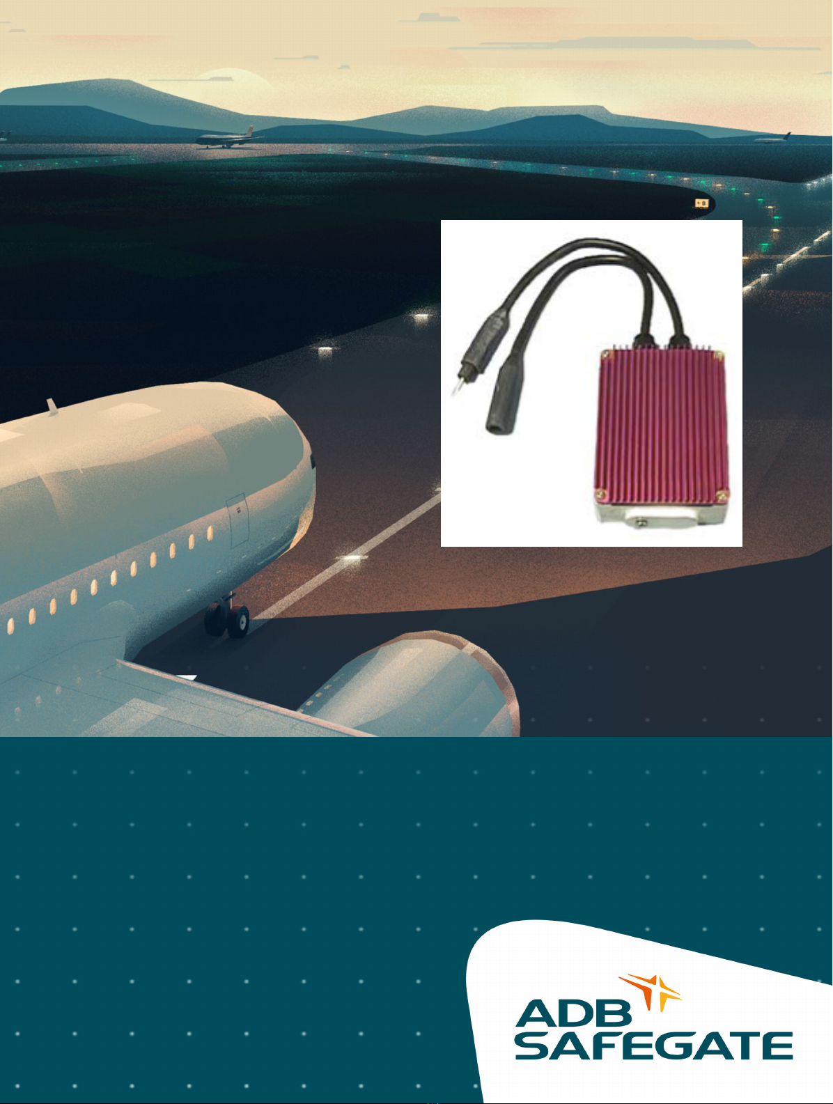
2.0 Airfield Lighting Field Lightning Arrestor
Airfield Lighting Field Lightning Arrestor (FLA) is designed to help reduce the susceptibility of airfield series circuits to
lightning strikes or surges. The FLA is designed to be installed at 600m (2000 ft) intervals in the 5KV airfield primary series
circuit but can be installed at closer intervals as desired. Each FLA adds additional local protection against damage from
lightning strikes reducing the risk of widespread damage in the field and to equipment in the electrical vault.
2.1 Field Lightning Arrestor
Compliance with Standards
FAA: Complies with AC 150/5345-10, Section 3.4.12 (Lightning/Surge Arrestors)
Overview
•For use on airfield series circuits to further reduce the risk of lightning damage on the series circuit
•Can be inserted at various points in the 5 kV airfield primary series circuit to provide additional lightning protection.
•Can be used on any airfield circuit (6.6 A from 4 kW to 30 kW and 20 A from 15 kW to 70 kW)
•Rated for 25,000 A peak (8/20 microsecond discharge)
•Assembly rated NEMA 6P
•Insulation resistance is 10 GΩ (minimum)
•Includes a UL 467 rated ground lug, which accepts an AWG 4 to AWG 14 earth ground wire
•Operating temperature: -55 °C to +55 °C (-67 °F to +131 °F)
Installation
It is recommended that the field lighting arrestor be installed a maximum of about every 2,000 feet around the series circuit,
starting at the first base can closest to the vault on each leg of the series circuit. Simply disconnect (unplug) the L-823
connectors at the designated point and plug in the field lighting arrestor. Connect a known good earth ground (25 Ω or less)
to the earth ground lug of the field lighting arrestor using at least an AWG 6 wire.
The field lightning arrestor can be installed in a base can (preferred) or direct earth buried. Heat shrink each L-823 connector
interface using an airport approved method. The field lighting arrestor body is waterproof (rated NEMA 6P) and is fully
resistant to deicing fluids.
Ordering Code
44A6102
Maintenance
There are no internal repairable parts since the field lighting arrestor is completely sealed. If the field lighting arrestor fails,
replace it with a new one. Note that the heat sink on a field lighting arrestor is colored red in order to differentiate it from the
ADB Safegate BRITE Remote. An ADB Safegate BRITE Remote has a silver colored heat sink.
Troubleshooting
The field lighting arrestor contains Metal Oxide Varistor (MOV) components similar to the type used on the output of
Constant Current Regulators. A degraded or failed field lightning arrestor is typically evidenced by a rapid drop in the overall
series circuit insulation resistance. Troubleshoot using same techniques used to find failed isolation transformers.
One or more shorted field lighting arrestors may cause a section of lights to be dim or out. If it is suspected that the field
lighting arrestor has internally shorted, measure between the male L-823 and the arrestor earth ground lug using an
ohmmeter. The meter should read a very high resistance. A failed unit will read a very low resistance or zero ohms.
96A0489, Rev. B, 2018/03/06 5
Copyright © 2017–2018 ADB Safegate, All Rights Reserved
After isolating a probable failed field lightning arrestor, make a visual inspection of the cord set and arrestor body for charring
or a bulged arrestor body (caused when surge currents in excess of the MOV rating passes through the field lightning
arrestor). If damage is suspected, replace the field lightning arrestor with a new one.
If it is suspected that the internal MOVs have degraded due to excessive surge current, causing a drop in insulation resistance
to earth ground, test as follows:
•Place the field lightning arrestor in a bucket of water
•Attach the red (+) lead of a megger to the male L-823 pin
•Connect the black (-) lead of the megger to the arrestor earth ground lug
•Meg the field lightning arrestor at 1000 VDC for one minute
•Replace the field lightning arrestor if resistance is less than 2 GΩ
2.2 Introduction
The Field Lightning Arrestor incorporates distribution class Metal Oxide Varistors (MOVs). When a voltage transient occurs,
the impedance of the MOVs changes from a near open circuit to a highly conductive path to ground, clamping the voltage to
a safe level to protect the equipment. After passage of the surge, the MOVs return to their initial state, conducting minimal
leakage current.
The manual shows the information necessary to:
•Install and maintain the Field Lightning Arrestor.
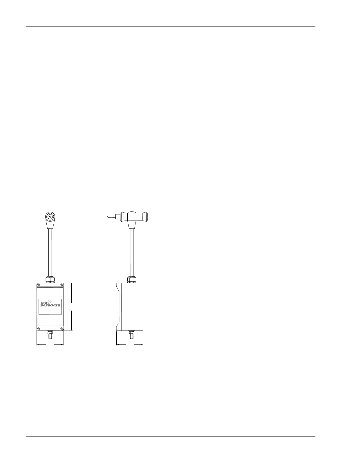
Dimensions
6.28
3.53 3.53
Field Lightning Arrestor
Rating: 5KV, 20 A
Part# AD071P01
Airfield Lighting Field Lightning Arrestor
Airfield Lighting Field Lightning Arrestor
6
Copyright © 2017–2018 ADB Safegate, All Rights Reserved
3.0 Installation
This manual provides the detailed procedures required to safely and correctly install the Field Lightning Arrestor.
3.1 Introduction to Safety
CAUTION
Unsafe Equipment Use
This equipment may contain electrostatic devices, hazardous voltages and sharp edges on components
• Read installation instructions in their entirety before starting installation.
• Become familiar with the general safety instructions in this section of the manual before installing,
operating, maintaining or repairing this equipment.
• Read and carefully follow the instructions throughout this manual for performing specific tasks and
working with specific equipment.
• Make this manual available to personnel installing, operating, maintaining or repairing this
equipment.
• Follow all applicable safety procedures required by your company, industry standards and
government or other regulatory agencies.
• Install all electrical connections to local code.
• Use only electrical wire of sufficient gauge and insulation to handle the rated current demand. All
wiring must meet local codes.
• Route electrical wiring along a protected path. Make sure they will not be damaged by moving
equipment.
• Protect components from damage, wear, and harsh environment conditions.
• Allow ample room for maintenance, panel accessibility, and cover removal.
• Protect equipment with safety devices as specified by applicable safety regulations
• If safety devices must be removed for installation, install them immediately after the work is
completed and check them for proper functioning prior to returning power to the circuit.
Failure to follow this instruction can result in serious injury or equipment damage
Additional Reference Materials
Important Information
•IEC - International Standards and Conformity Assessment for all electrical, electronic and related technologies
•IEC 60364 - Electrical Installations in Buildings
•FAA Advisory: AC 150/5340-26 (current edition) Maintenance of Airport Visual Aid Facilities
•ANSI/NFPA 79, Electrical Standards for Metalworking Machine Tools.
•National and local electrical codes and standards.
3.2 Inspection on Arrival
Please inspect the Field Lightning Arrestor upon arrival. Note any issues and contact the shipper.
96A0489, Rev. B, 2018/03/06 7
Copyright © 2017–2018 ADB Safegate, All Rights Reserved

3.3 Storage
CAUTION
IMPROPER STORAGE
If equipment is to be stored prior to installation, it must be protected from direct sunlight.
Failure to follow this instruction can result in equipment damage
For proper storage, place the box of the product on a shelf or in a warehouse.
3.4 Installation Procedures
WARNING
• Protect from electrostatic discharge.
• The Field Lightning Arrestor assembly must be grounded to a low resistance earth ground.
• Failure to ground the FLA assembly will result in no added protection to the circuit.
Failure to follow this instruction can result in equipment damage
To install the Field Lightning Arrestor (FLA) into the series circuit, perform the following procedure:
1. Determine the specific location for the FLA to be installed in the circuit.
Note
It is recommended that the Field Lightning Arrestor assembly be installed approximately every 2000 feet around
the series circuit starting at the first useable L867/L868 light base can outside the vault on each side of the series
circuit. At the airport’s option, Field Lightning Arrestors may be installed more frequently if it is desired to further
reduce lightning risk.
2. Remove the light fixture from the L867/L868 light base can and disconnect one L-823 connection from the airfield series
circuit. This could be from the L-830 isolation transformer or a splice found in the light base.
3. Plug in the lightning arrestor as shown in the wiring diagram. See Figure 1 and hook-up label on enclosure.
4. After the connection has been made, reinstall heat shrink (in accordance with local heat shrinking practice).
5. Check site plan drawings and specifications to verify the presence and location of the counterpoise lightning wire. Wiring
intended to be connected to a safety ground should not normally be attached to the FLA. See FAA AC 150/5340-30
(current edition) for further discussion about lightning and safety grounds on series circuits.
Note
IF COUNTERPOISE LIGHTNING WIRE IS PRESENT, connect a 4 AWG (minimum) copper grounding wire, to the
ground screw on end of the FLA enclosure and attach the other end of the ground wire to the counterpoise wire
using an appropriate attachment method.
Note
IF COUNTERPOISE LIGHTNING WIRE IS NOT PRESENT, an 8 ft. (min) long copper clad steel grounding rod may
have to be added in the vicinity of the FLA. It may be possible in some locations to add the ground rod through a
pre-existing hole in the bottom of the light base can. Connect ground wire between the grounding screw on the
enclosure using a UL 467 ground lug, or equivalent, and the grounding rod.
Airfield Lighting Field Lightning Arrestor
Installation
8
Copyright © 2017–2018 ADB Safegate, All Rights Reserved

Note
Depending on the design of the counterpoise lightning system, connecting the FLA directly to a dedicated ground
rod may provide more effective protection of the circuit.
6. After the FLA has been installed, reinstall the light fixture back onto the light base and torque the mounting bolts to the
required torque specifications found in the equipment product manual.
Figure 1: Connection Diagram
Field Circuit
Connection
(6.6 A or 20 A)
Secondary
to Airfield Light
Field Circuit
Connection
(6.6 A or 20 A)
Field Circuit
Connection
(6.6 A or 20 A)
Field Circuit
Connection
(6.6 A or 20 A)
Field Circuit
Lightning Arrestor
(part# AD071P01)
Customer Supplied
Connection #6 AWG min.
Counterpoise or
Copper-clad
Ground Rod
L-830
Field Lightning Arrestor
Rating: 5KV, 20 A
Part# AD071P01
3.5 Equipment Specification Data
Table 1: Operating Specification
Model FLA
Nominal Voltage 6 KV
Continuous Operation Voltage 5.1 KV
Duty Cycle
10 kA crest (20 current surges)
40 kA crest (2 current surges)
8 / 20 µs waveshape
High Current Discharge (Short Duration) 100 kA crest (2 current surges)
4 / 10 µs waveshape
Low Current Discharge (Long Duration) 250A crest (20 current surges) 2000 µs duration
Maximum Discharge Voltage 19.8kV Crest @ 10kA, 24.7KV Crest @ 40kA 8 / 20 µs waveshape
Protection Index IP68 (NEMA 6P)
Operating Temperature -40°F to +140°F (-40°C to +60°C)
Weight 2 kg (4.4 lb)
96A0489, Rev. B, 2018/03/06 9
Copyright © 2017–2018 ADB Safegate, All Rights Reserved

Airfield Lighting Field Lightning Arrestor
Installation
10
Copyright © 2017–2018 ADB Safegate, All Rights Reserved
4.0 Troubleshooting
WARNING
ELECTRIC SHOCK HAZARD
• Do not operate a system that contains malfunctioning components. If a component malfunctions,
turn the system OFF immediately.
• Disconnect and lock out electrical power.
• Allow only qualified personnel to make repairs. Repair or replace the malfunctioning component
according to instructions provided in its manual.
• High voltage is present in an airfield series circuit which may result in personal injury, death, or
damage to the equipment.
• A failed Field Lightning Arrestor case may be live. DO NOT troubleshoot the Field Lightning Arrestor
on a live field circuit. Failure to disconnect the power supply may result in personal injury, death, or
damage to the equipment.
Failure to follow these warnings will result in death or equipment damage.
The Field Lightning Arrestor (FLA) is connected between the series circuit and earth ground. If damage to any FLA is
suspected, remove the series circuit wires from the output of the CCR and meg the entire series circuit. Compare this meg-
ohm reading with previously recorded readings. If there has been a sudden, significant drop in the meg-ohm reading, a
damaged FLA may be present. See FAA AC 150/5340-26, Chapter 5 for guidance on expected meg readings on new circuits
and normal degradation of existing circuits. Isolate the suspected failed FLA using normal series circuit troubleshooting
techniques. Note that the source of lowered insulation resistance may be due to existing series circuit wiring or isolation
transformers. See FAA Advisory Circular 150/5340-26 (current edition) for series circuit troubleshooting guidance.
Note
Series circuit insulation resistance is normally tested using either 500Vdc or 1000Vdc. The insulation resistance of
series circuits with Field Lightning Arrestors can be tested with voltages up to 5000Vac or 7070Vdc.
The following physical evidence may be present as a result of lightning strike(s):
•A section of the airfield circuit may be dim or not lit.
•Visual evidence of physical damage to either cordset or the FLA enclosure.
•Ground wire is missing (vaporized).
•Burnt smell is present.
The following troubleshooting may be performed on the FLA to further determine if the device has failed:
•Remove the FLA from the series circuit.
•Connect an ohmmeter from the male connector pin to the female connector pin. The measured resistance should be less
than 2 ohms. If the resistance is significantly higher, the lead connectors have been damaged. If the resistance is infinity,
there is an open in the cordset wiring. In either case, the FLA must be replaced.
•See Figure 2. Connect the FLA to some mating cordsets and drop the FLA in a bucket of water. Connect the positive (red)
terminal of a meg-ohm meter to the cordset leads. Put the negative (black) terminal of the meg-ohm meter in contact
with the water or the ground wire. This is typically done by attaching a wire to a metal plate and dropping the metal plate
in the water. Bring the attached wire out of the water and connect it to the negative terminal of the meg-ohm meter. Meg
96A0489, Rev. B, 2018/03/06 11
Copyright © 2017–2018 ADB Safegate, All Rights Reserved
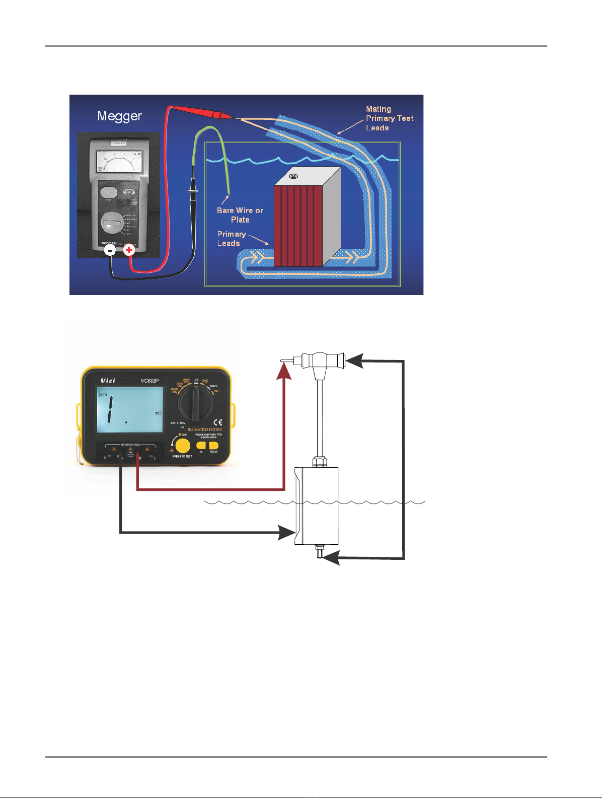
the FLA at 1000VDC for 1 minute. At the end of 1 minute, the insulation resistance should be greater than 2G ohms. If the
resistance is less than 2G ohms, replace the FLA.
Figure 2: FLA Field Insulation Resistance Check
Megger
Jumper
Airfield Lighting Field Lightning Arrestor
Troubleshooting
12
Copyright © 2017–2018 ADB Safegate, All Rights Reserved

Company Addresses
ADB SAFEGATE ADB Safegate Address:
Leuvensesteenweg 585,
B-1930 Zaventem, Belgium
Contact:
Tel.: +32 2 722 17 11,
Fax: +32 2 722 17 64
Email: [email protected]
Internet: www.adbsafegate.com
ADB SAFEGATE Americas LLC ADB Safegate, Americas Address:
977 Gahanna Parkway,
Columbus, OH 43230
USA
Contact:
Tel.: +1 (614) 861 1304,
Fax: +1 (614) 864 2069
Email: [email protected]
Internet:www.adbsafegate.com
ADB Safegate Airfield Technologies Ltd. China ADB Safegate, China Address:
Unit 603, D Block,
CAMIC International Convention Center,
No 3, Hua Jia Di East road, ChaoYang district,
Beijing 100102, P.R. China
Contact:
Tel.: +86 (10) 8476 0106,
Fax: +86 (10) 8476 0090
Email: [email protected]
Internet:www.adbsafegate.com
96A0489, Rev. B, 2018/03/06 13
Copyright © 2017–2018 ADB Safegate, All Rights Reserved

Table of contents
Popular Industrial Electrical manuals by other brands


National Instruments
National Instruments SCXI-1332 installation instructions

Eaton
Eaton NZM3-XR Series Instruction leaflet

Murata
Murata GJM0335C1E3R6CB01 Series Reference sheet

TeeJet Technologies
TeeJet Technologies e-ChemSaver 115880 Maintenance instructions

Murata
Murata GCM188R71H102JA37 Series Reference sheet

Murata
Murata GRM155R71H333ME14 Series Reference sheet