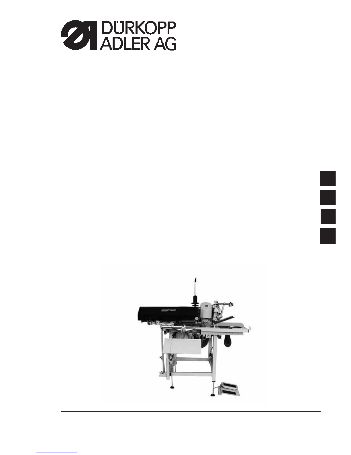
Adler 745-34 Speedpocket User manual

Manual, complete
745 - 34 Speedpocket
Sewing unit for runstitching
of rectangular piped pockets
Operating Instructions
Installation Instructions
Service Instructions
Instructions for programming DAC
Postfach 17 03 51, D-33703 Bielefeld • Potsdamer Straße 190, D-33719 Bielefeld
Telefon + 49 (0) 5 21 / 9 25-00 • Telefax + 49 (0) 5 21 / 9 25 24 35 • www.duerkopp-adler.com
1
2
3
4
Ausgabe / Edition: 08/2005 Printed in Federal Republic of Germany Teile-Nr./Part.-No.: 0791 745171

745 - 34 Speedpocket
Manual, complete
Summary
Operating Instructions
Installation Instructions
Service Instructions
Instructions for programming DAC
Interconnection diagram
9870 745131 B
9890 745001 B
Pneumatic circuit plan
9770 745002

Index Page:
Part 2: Installation Instructions 745-34 Speedpocket
1. Scope of delivery .............................................. 3
2. General notes ................................................ 3
3. Installing the sewing unit
3.1 Transport.................................................... 4
3.2 Removingthesecuringdevices...................................... 5
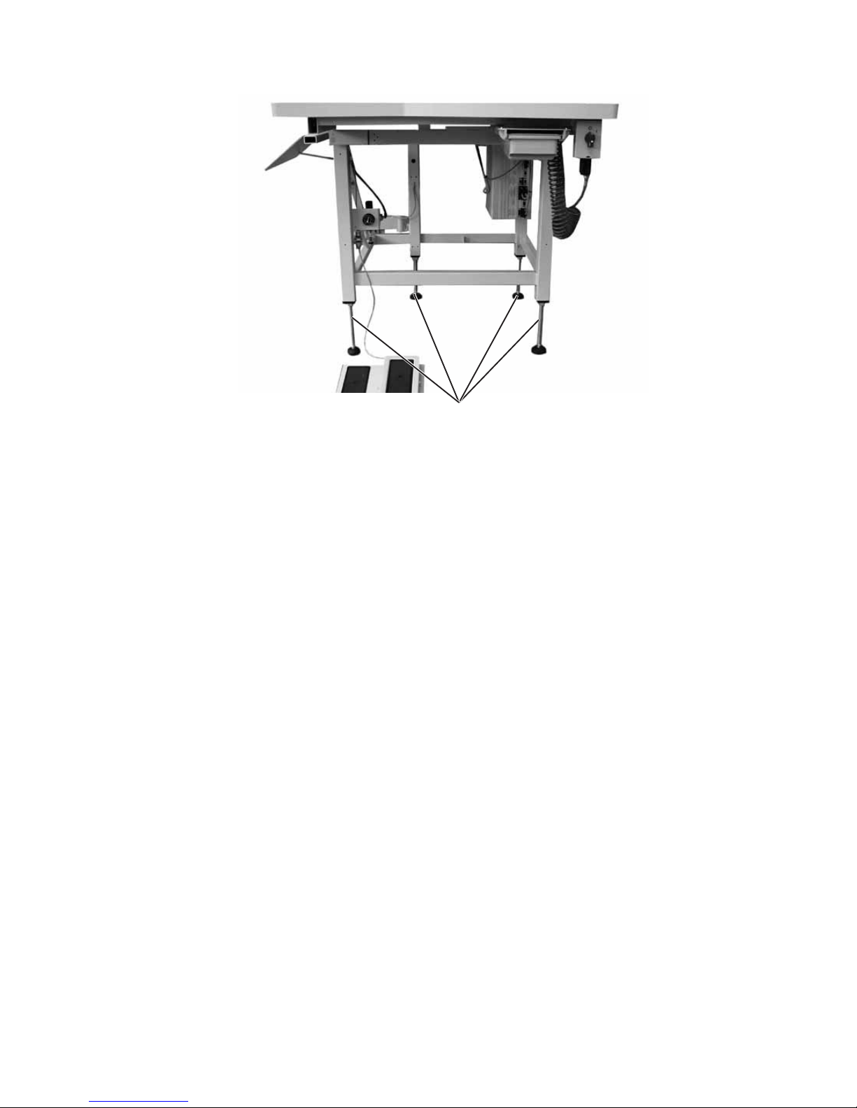
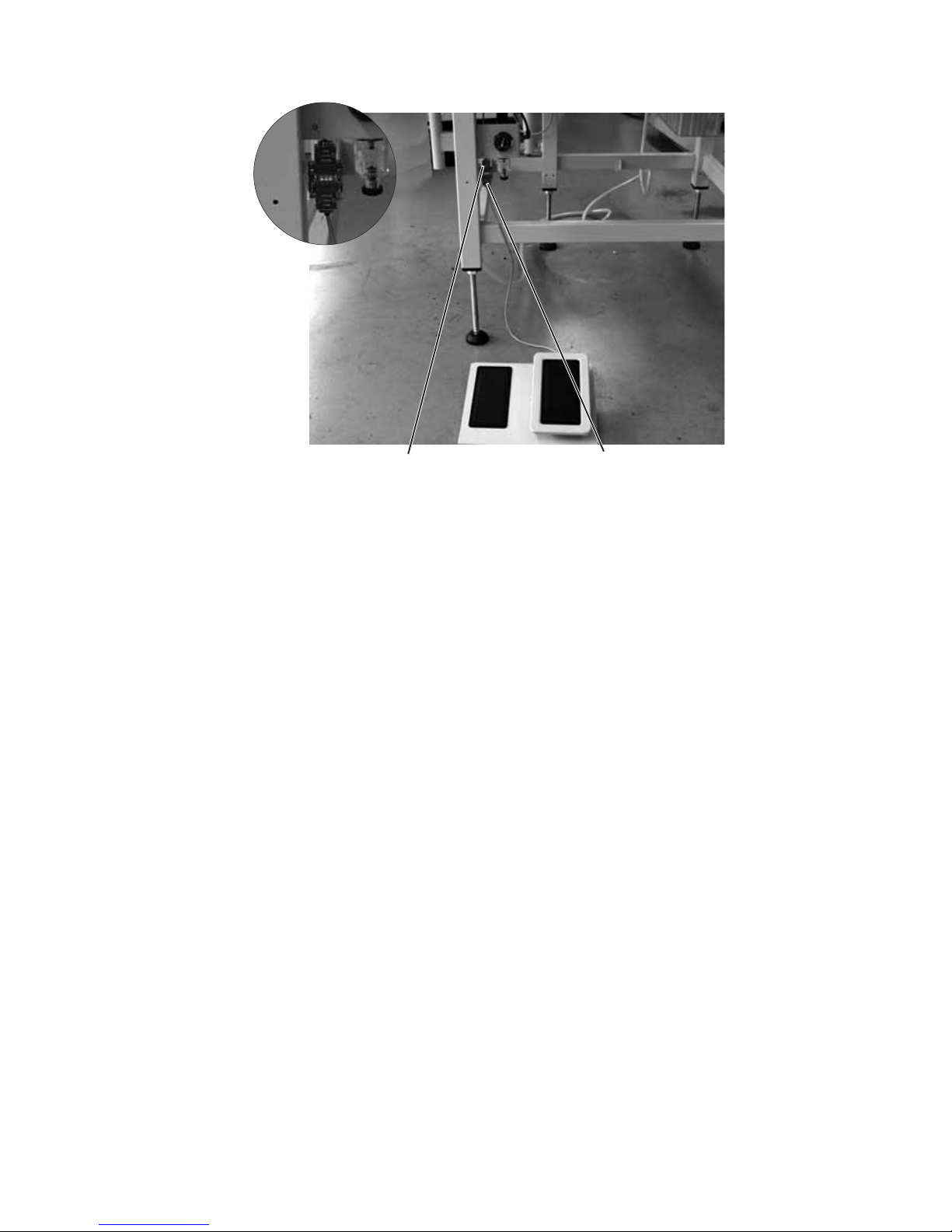
3.3 Settingtheworkingheight ......................................... 6
3.4 Connecting the foot pedal.......................................... 7
4. Attaching the machine parts removed for shipping
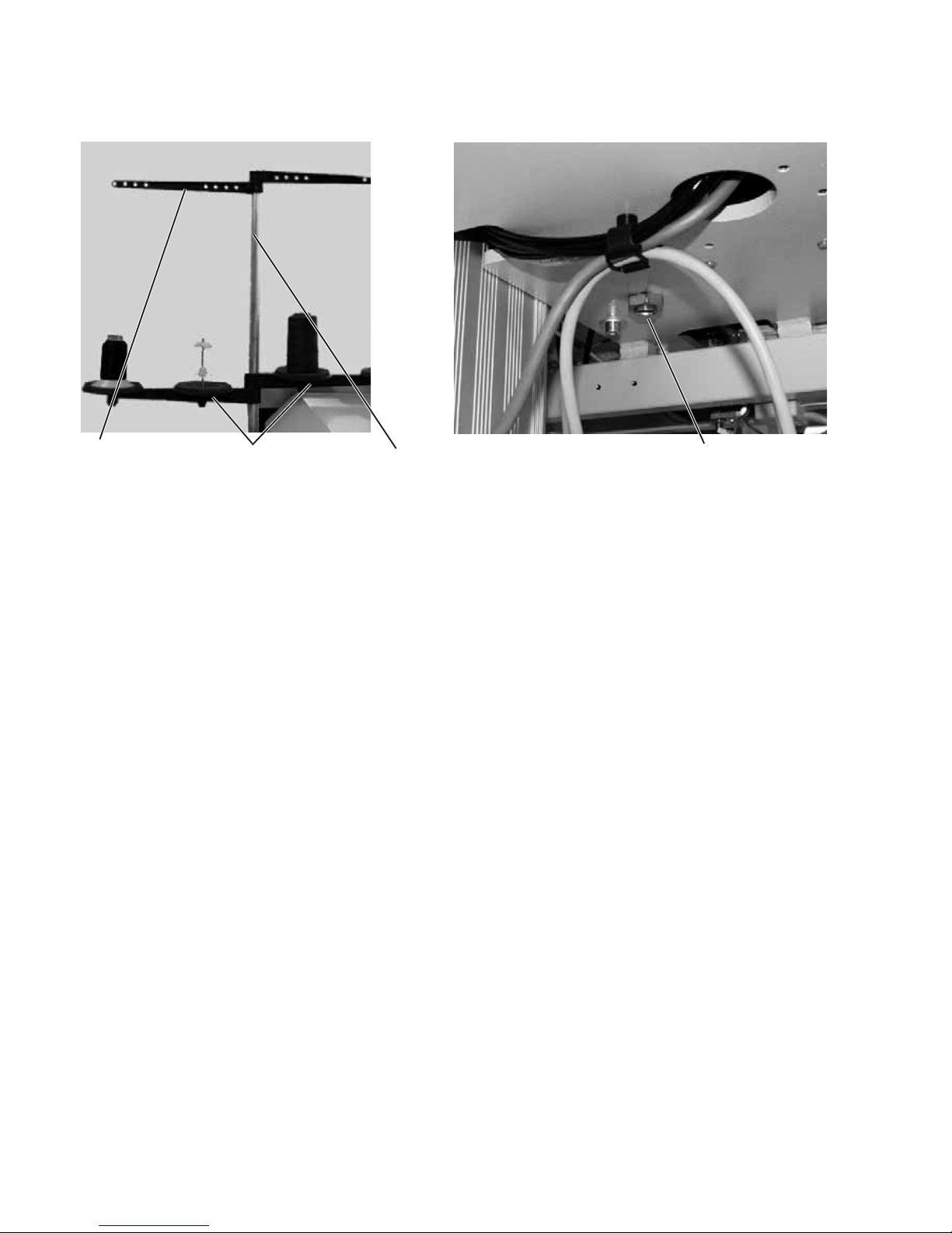
4.1 Threadreelholder.............................................. 8
4.2 Fastening the control panel and the bobbin winder........................... 9
4.3 Pincer stacker (optional equipment) ................................... 10
5. Electrical connection
5.1 Connecting the control panel DAC III C ................................. 11
5.2 Connecting the external bobbin winder .................................. 11
5.3 Making the mains connection ....................................... 11
5.4 Directionofrotationofthesewingmotor................................. 12
6. Pneumatic connection ........................................... 13
7. Oil lubrication ................................................ 14
8. Commissioning ............................................... 15
9. Software installation
9.1 General..................................................... 15
9.2 Loading the program ............................................. 16
9.3 Dongle-Update via Internet ......................................... 17


1. Scope of delivery
–Basic sewing unit for runstitching of piped pockets with rectangular
pocket corners, consisting of:
–Height-adjustable stand (manual)
–Step motor for material feed
–DC direct sewing drive
–Twin needle lockstitch machine
–DAC III control with control panel
–Laser marking lamps
–Compressed air maintenance unit with compressed air pistol
–Thread reel holder
–Tools and small parts in the accessories
–Feeding and sewing equipment according to the working
method
–Optional equipment
2. General notes
ATTENTION !
The sewing unit must only be assembled by trained specialist staff.
Any work on the electrical equipment of the sewing unit must
only be carried out by electricians or correspondingly instructed
persons.
The mains plug must be pulled out.
The enclosed operating instructions of the step motor manufacturer
have to be observed in any case.
3

4
3. Installing the sewing unit
3.1 Transport
ATTENTION !
Do not lift the sewing unit at the table tops.
Use an elevating platform truck or a forklift truck.
ATTENTION!
Before commissioning the sewing unit screw out the stand feet 1 until a
secure footing is achieved.
Lifting the sewing unit
–Only with elevating platform truck or forklift forks.

3.2 Removing the securing devices
Before installing the sewing unit all six securing devices have to be
removed.
If the sewing unit has to be transported to another place, please use
the securing devices again.
5
1
2
3
4
5
6

3.3 Setting the working height
The working height can be set between 79 cm and 98 cm (measured
up to the upper edge of the table top).
The sewing unit is set to the lowest working height of 79 cm by the
manufacturer.
–Set the sewing unit to the desired height with the mandril screw
spindles 1.
6
1

3.4 Connecting the foot pedal
–Push plug 1 of the foot pedal into the plug socket 2 at the stand.
7
21

4. Attaching the machine parts removed for shipping
4.1 Thread reel holder
–Insert thread reel holder 1 in the drill-hole of the table top and
fasten it underneath the table top with nut 4.
–Mount and align reel plate 2 and unwinding arms 3 as shown in the
illustration.
8
432 1

4.2 Fastening the control panel and the bobbin winder
The holder 1 for the control panel and the external bobbin winder is
fastened on the right side of the machine head, as seen by the
operator.
–Fasten control panel 1 on location bolt 3 for the folding station with
nut 2.
–Afterwards fasten earth cable 5 with screw 4.
–Fasten bobbin winder 6 on bolt 7 with screw 8.
9
54 3 21 87 6

4.3 Pincer stacker (optional equipment)
The pincer stacker 1 (Order No. 0745 427514) is fastened to the stand
of the sewing unit with two fastening screws 2.
Basic position
·Stacker bow at the front, stacker tongs open.
The open stacker tongs 3 should be positioned 20-25 mm in front
of the table top so that the workpiece can pass by.
·With the stop signal the stacker tongs moves to the front and grips
the workpiece.
·The stacker bow swivels to the back pulling the workpiece from the
table top.
–Adjust the movement of the stacker bow with the throttling devices
in such a way that no jerky movements can be made.
·The stacker tongs opens.
·The workpiece is placed on top of the stacker plate 4.
The height of the plate has to be positioned in such a way that the
workpiece is put down safely.
·The stacker bow swivels to the front.
10
21 43

5. Electrical connection
ATTENTION!
Any work on the electrical equipment of the sewing unit must
only be carried out by electricians or correspondingly instructed
persons.
The mains plug must be pulled out.
5.1 Connecting the control panel DAC III
The control panel has been removed for shipping.
–Carefully insert plug 1 into the rear panel of the control panel.
–Tighten screws of plug 1.
–Tighten control panel on holder with screws 2.
5.2 Connecting the external bobbin winder
–Insert plug 4 of the bobbin winder into socket 3 underneath the
table top and secure with cap nut.
5.3 Making the mains connection
–Connect the mains plug 230 Volt - 50\60 Hz.
11
43
21

5.4 Direction of rotation of the sewing motor
The sewing unit is equipped with the latest step motor technology. A
check of the direction of rotation is not required because it is
automatically set by the control.
12

6. Pneumatic connection
For the operation of the pneumatic components the sewing unit has to
be supplied with anhydrous compressed air.
ATTENTION !
For a trouble-free function of the pneumatic control procedures the
compressed air supply must operate as follows:
Even at the moment of the highest air consumption the minimum
operating pressure must not drop below 6bar.
In case of a too high loss of pressure:
–Increase the compressor output.
–Increase the diameter of the compressed air hose.
Connecting the maintenance unit for compressed air
–Connect the connection hose (Order No. 0797 003031) to the
pressure regulator 3 by means of a hose coupling ¼ “.
Adjusting the operating pressure
–The operating pressure amounts to 6 bar.
It can be read off at the manometer 2.
–For adjusting the operating pressure lift the twist handle 1 and turn
it.
–Turning in clockwise direction = the pressure is increased
–Turning counter-clockwise = the pressure is reduced
ATTENTION !
No oil-bearing compressed air must be fed from the compressed air
line.
Behind the filter cleaned compressed air is withdrawn as blowing air
for cleaning machine parts and for blowing workpieces out.
Oil particles contained in the blowing air lead to malfunctions and
stains on the workpieces.
13
1
2
3

7. Oil lubrication
Caution: Danger of injury !
Oil can cause skin rashes.
Avoid longer skin contact.
After contact wash yourself thoroughly.
ATTENTION !
The handling and disposal of mineral oils is subject to legal
regulations.
Deliver used oil to an authorized collecting station.
Protect your environment.
Be careful not to spill any oil.
For filling up the oil reservoirs use nothing but DA-10 lubricating oil or
an equivalent oil with the following specification:
–Viscosity at 40° C: 10 mm2/s
–Ignition point: 150° C
DA-10 is available from the DÜRKOPP ADLER AG sales offices under
the following parts numbers:
250 ml Container: 9047 000011
1 l Container: 9047 000012
2 l Container: 9047 000013
5 l Container: 9047 000014
Oil reservoir for lubrication of the machine head
–Fill oil reservoir 1 with oil through the drill-holes in the inspection
glass.
The oil level must be between the “Min” and “Max” markings.
Oil reservoir for hook lubrication
–Tilt the machine head up until the locking bow snaps in
(see Operating Instructions Chapter 2.3)
–Fill oil reservoir 2 with oil up to the “max.” marking through nipple 3
(see sketch).
14
32 1
32

8. Commissioning
After completion of the installation work a sewing test should be made.
–Insert the mains plug.
Caution: Danger of injury!
Switch off the main switch before threading in needle and hook thread.
Laser light.
Do not look into the light source.
–Thread in the needle thread (see Operating Instructions
Chapter 2.5).
–Thread in the hook thread (see Operating Instructions
Chapter 2.7).
–Switch on the main switch.
The control is initialized.
–Step back on the pedal.
The reference run starts.
The transport carriage moves in its rear end position.
The reference run is necessary in order to get a defined initial
position of the transport carriage.
–By actuating the pedal the various steps of the positioning
procedure are triggered sequentially and the sewing cycle is
started.
ATTENTION !
At the sewing start the workpiece must lie under the feeding clamps.
Movement of the transport carriage without material damages the
coating of the feeding clamps.
–For selecting the sewing program and for further settings of the
control unit see Part 4: Programming Instructions 745-34
Speedpocket.
–Positioning and operation are described in Part 1: Operating
Instructions 745-34 Speedpocket.
9. Software installation
9.1 General
Loading a specific sewing software in the DACIII control unit is
possible with the help of the “Programmed Dongle”. The “Programmed
Dongle” has a label indicating the class and software version.
Such a loading (booting) may be used in order to provide several
DACIII control unit with a sewing software (first installation) or to install
a newer machine software (update).
15

With the delivery of the machine only the test software (allowing the
loading of sewing software) is installed in the control unit.
The test software offers no further functions. If the test software gets
damaged during the loading process, it is no longer possible to load a
software using a dongle.
In such a case use a PC with the loader cable.
Important !
The machine software is already included by the delivery of the sewing
unit.
CAUTION !
Turn off the main switch before connecting the dongle.
9.2 Loading the program –Turn the machine off at the main switch.
–Insert the dongle 2into the socket X110 (TEST-Interface) 1of the
control unit (see pictures).
–Switch on the main switch. The Software will be loaded. The
loading process takes less than 60 seconds.
–During the loading process do not remove the dongle and not
switch off the machine (you will damage the Software) !
–During loading the program version of the operation panel will be
displayed, e.g. “BF4 A02”.
–When loading is completed the new program version will be
displayed, e.g. “745 A01”.
–Remove the dongle 2of the X110.
–For safety reasons: please confirm the new operation program
before the first start of the sewing unit with the button ”OK”.
–The machine is now ready for use.
Important !
Remove the dongle before the next switch-on, otherwise the sewing
software will be reloaded again.
After exchanging the DAC III control box and loading the machine
software, the following messages will appear, Error 9900 or Error 9901
or Error 9902. In the next step a complete reset of the machine
software must be done.
Please follow part 4 chapter 6 of the programming instructions.
In this chapter under the menu item 504 all parameters for machine-
pocket parameters and sequence are set to default values.
Then the machine parameters 400 to 407 must be accordingly.
16
1
2

9.3 Dongle-Update via Internet
Dongles can be updated with programs available from the Dürkopp
Adler homepage. Please open our homepage
(www.duerkopp-adler.com ) where you will find the relevant programs
in the “Download” - section. Prerequisite is our auxiliary download
software “ Dongle Copy ” which is available in the same section
together with instructions for easy use.
17

Note:
18
Table of contents
Other Adler Sewing Machine manuals