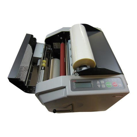
Advanced Greig Laminators, Inc. Compadre User manual

OPERATORS MANUAL
FOR
Compadre
801 Burton Blvd. DeForest WI 53532
Ph: 608-846-7016 Fa : 608-846-1024
E-mail: info@aglaminators.com

Table of Contents
Table of Contents
Chapter 1 Installation
Selecting Area - - - - - - - - - - - - - - - - - - - - - - - - - - - - - - - - - - - - - - - - - - - - - - - - - - 1-1
Electrical Connection - - - - - - - - - - - - - - - - - - - - - - - - - - - - - - - - - - - - - - - - - - - - - 1-2
Pneumatic Connection - - - - - - - - - - - - - - - - - - - - - - - - - - - - - - - - - - - - - - - - - - - - 1-2
Chapter 2 Specifications
Machine Dimensions - - - - - - - - - - - - - - - - - - - - - - - - - - - - - - - - - - - - - - - - - - - - - - 2-1
Electrical Requirements - - - - - - - - - - - - - - - - - - - - - - - - - - - - - - - - - - - - - - - - - - - -2-1
Pneumatic Requirements - - - - - - - - - - - - - - - - - - - - - - - - - - - - - - - - - - - - - - - - - - -2-1
Material Capacity - - - - - - - - - - - - - - - - - - - - - - - - - - - - - - - - - - - - - - - - - - - - - - - - 2-1
Chapter 3 Safety
General Machine Safety - - - - - - - - - - - - - - - - - - - - - - - - - - - - - - - - - - - - - - - - - - - -3-1
Operator Safety - - - - - - - - - - - - - - - - - - - - - - - - - - - - - - - - - - - - - - - - - - - - - - - - - -3-1
Chapter Operation
General - - - - - - - - - - - - - - - - - - - - - - - - - - - - - - - - - - - - - - - - - - - - - - - - - - - - - - - 4-1
Right Hand Control Panel, Figure 1 - - - - - - - - - - - - - - - - - - - - - - - - - - - - - - - - - - - -4-2
Laminator Setup - - - - - - - - - - - - - - - - - - - - - - - - - - - - - - - - - - - - - - - - - - - - - - - - - 4-3
Process Output Trouble Shooting - - - - - - - - - - - - - - - - - - - - - -- - - - - - - - - - - - - - - -4-4
Process Control Chart - - - - - - - - - - - - - - - - - - - - - - - - - - - - - - - - - - - - - - - - - - - - 4-6
Chapter 5 Maintenance
Nip Roll Section - - - - - - - - - - - - - - - - - - - - - - - - - - - - - - - - - - - - - - - - - - - - - - - - - -5-1
Checking the Nip - - - - - - - - - - - - - - - - - - - - - - - - - - - - - - - - - - - - - - - - - - - - - - - - -5-1
Zeroing the Nip - - - - - - - - - - - - - - - - - - - - - - - - - - - - - - - - - - - - - - - - - - - - - - - - - - 5-1
Cleaning the Nip Rolls - - - - - - - - - - - - - - - - - - - - - - - - - - - - - - - - - - - - - - - - - - - - - 5-1
Roller Open and Close Rate - - - - - - - - - - - - - - - - - - - - - - - - - - - - - - - - - - - - - - - - -5-2
Lubrication - - - - - - - - - - - - - - - - - - - - - - - - - - - - - - - - - - - - - - - - - - - - - - - - - - - - - 5-2
Chapter 6 Warranty
Limited Warranty - - - - - - - - - - - - - - - - - - - - - - - - - - - - - - - - - - - - - - - - - - - - - - - - - 6-1
Chapter 7
Schematics
Electrical - - - - - - - - - - - - - - - - - - - - - - - - - - - - - - - - - - - - - - - - - - - - - - - - - - - - - - -7-1
Pneumatic - - - - - - - - - - - - - - - - - - - - - - - - - - - - - - - - - - - - - - - - - - - - - - - - - - - - - 7-2

Installation
1-1
Selecting Area
Select an area that has a smooth, level surface for the laminator to set on, this will allow for easier
maneuverability of the machine if it requires moving later on. The area should be large enough to allow
an operator ample room to properly handle your largest product on the infeed and outfeed sides of the
laminator. The sides of the laminator should also be easily accessible in case service or maintenance is
required. AGL appro imates this area should be about 7-8 feet in front and back of the machine and 3-4
feet on either end. This is only a suggestion, your plant and the products to be laminated will be the
determining factor.
The laminator is a large heavy piece of equipment. Do not attempt to
move the machine with one person. Injury is possible as well as
permanent damage to the laminator. The laminator should only be
rolled on a relatively smooth and level surface. Tipping or forcing the machine over large bumbs
can destroy the alignment of the rolls, idlers, and unwind/windup shafts. This alignment is
required for proper lamination. Advanced rieg Laminators, Inc.’s warranty does not cover
malfunction of the machine due to improper handling of the machine during installation.
Do Not use a knife or other sharp object to remove the shrink wrap
from the laminator and the protective coverings from the rolls. This
can cause irreparable damage to the laminator enclosures and rolls.
Electrical Connection
Refer to the Electrical Requirements under Specifications for the proper requirements for your
laminator. All connections to components and terminal blocks should be checked for tightness before
initial startup. This will help avoid and electrical problems caused by connections that may have loosened
due to vibration during shipping. The circuit breaker on the laminator is not considered a disconnect
device. Consult a qualified, licensed electrician to ensure that the power supply for the machine is
properly installed in your facility. Use supplied power cord and a standard outlet to provide power to the
laminator. Advanced Grieg Laminators, Inc. will not be responsible for damage caused by incorrect
electrical installation. Before initial startup, check all switches to make sure they are in the off or open
position.
Pneumatic Connection
Refer to the Pneumatic Requirements under Specifications for the proper requirements for your laminator.
The air supply should be clean, dry, and regulated. Failure to properly clean and dry the air supplied to
the laminator will cause damage to the cylinders and valve. The laminator is supplied with a 1/4npt port
for your final connection located in the lower right rear of the machine.
The air supply to the laminator must be clean and dry. Particles and
moisture can damage the cylinders, brakes and clutches.
Before laminating with your new laminator, the open close rate of the nip and pull rolls must be checked.
Refer to the maintenance section under Roller Open and Close Rate.

Specifications
2-1
Machine Dimensions
Width: 83”
Height: 54”
Depth: 25.5”
Weight: 1600 lbs.
Electrical Requirements
115 VAC single phase, 50/60 Hz, 15 Amp service
Pneumatic Requirements
Appro imately 1-2 cfm at 90 psi line pressure supplied via your cleaned/dried/regulated plant air.
Material Capacity
Upper Rear Station: 7.0” Diameter 62 long 3” Diameter core. Standard
Upper Front Station: 7.0” Diameter 62 long 3” Diameter core. Standard
Lower Front Station: 7.0” Diameter 62 long 3” Diameter core. Standard

Safety
3-1
IMPORTANT
READ THIS SECTION BEFORE OPERATIN YOUR LAMINATOR
General Machine Safety
The following messages are written here for your safety, all operators and others around the laminator
should read, understand and follow these messages.
1. Read and understand all the safety instructions.
2. Keep this manual in a place where it can be easily referenced by all operators.
3. All connections to components and terminal blocks should be checked for tightness before
initial startup. This will help avoid and electrical problems caused by connections that may
have loosened due to vibration during shipping.
4. Use only the recommended power source to run the laminator. Consult a qualified and licensed
electrician if you are unsure of the power supply and the safety features of the supply.
5. If power supply cord is run across the floor, provide adequate protection to the cord to avoid damage
from foot traffic, dropped items or rolling items.
6. Do not attempt to service the laminator without qualified personnel available. Damage to the machine
or injury to you could be caused by moving parts or high voltage.
7. Do not operate the laminator with out all guards in place. If a guard is damaged or not working
properly, replace or repair before returning the machine to operation. If the machine is run without all
guards in place the safety obligation of the manufacturer is null and void.
8. Do not insert fingers, hands, or items into openings in the sideframes. Items may become entangled
in moving parts or in contact with high voltage.
9. Disconnect or lockout power from machine when any service is required and when cleaning the nip
rolls.
10. Disconnect or lockout power from the machine and refer to service personnel if the performance of
the machine changes indicating a problem or if machine does not operate normally to correct
operational procedures.
11. Adjust only items specifically covered by the operations portion of this manual. Any other
adjustments may create problems in performance in your machine and may require servicing by
qualified personnel to get machine back in correct working condition.
Operator Safety
Your laminator is designed to protect the operator from injury when used properly. Do not operate the
machine until you have read and understand this manual and without all guards and protection devices in
place, serious injury could occur.
The nip section can pull you into laminator! Do not place fingers
into the nip section when the rolls are rotating. It is recommended
that operators tie long hair back and not wear neckties, loose
clothing and jewelry since they can be caught in the nip section and
pull the operator into the machine. Proper equipment such as
gloves should be used if the material being laminated requires it.
The nip rolls will lower if there is a loss of air pressure.
The nip section is protected by a photoelectric eye that shoots a light beam across the machine in front of
the nip rolls. When the machine is in continuous run mode, the rolls will stop when the beam is broken by
an item too close to the nip section. However, if the machine is in jog mode, an alarm will sound warning
the operator that he/she is very close to the nip section, but the rolls will not stop rotating. The jog mode
is useful for starting prints into the laminator and smoothing the print corners out as they enter the nip
section, but this mode should be used as sparingly as possible since it puts the operator at a greater risk
than the run mode.
When the machine is in jog mode, an alarm will sound to warn the
operator but the rolls will not stop rotating when the light beam is
broken. Use this mode sparingly and with respect.
There are E-stop switches on all four corners of the machine, as well as an E-stop ribbon switch in front
and back. The machine will stop and the nip section will open if any of these switches are tripped.
Striking the red mushroom heads on the switches with your palm can activate the two switches. The
ribbon switches can be tripped by stepping on the yellow ribbon. The machine must be reset after and E-
stop condition has occurred. Refer to the Operation section for further details.

Operation
4-1
General
1. Main Power Switch: A switch in the lower right rear switches the main power on and off. The switch
is labeled clearly so the operator can tell if the power is on or off.
2. Power Button: The power button is used to start the machine initially and restart the machine after an
E-stop condition has occurred. After the power is turned on, the reset button is held for 15 seconds to
allow the machines electrical controls to reset to initial settings. The button will illuminate if machine
has been properly reset.
3. Speed: A potentiometer is used to control the speed that the laminator will run product. Your
laminator has the electrical and mechanical capability to run up to 10 feet per minute, but the quality
of the product output is the governing factor in ma imum process speed.
4. E-stops: E-stop switches are located in the front to allow the operator to stop the machine and open
the nip rolls and pull rolls in case of emergency. The button must be pulled back out before pressing
the power button to restart the machine.
5. Nip Rolls: The nip rolls are the heart and soul of the laminator and must be cared for properly in
order to give years of quality product output. Always dial the shim wheel to a shim setting greater
than “0” when the machine is not in use. This will prevent the rolls from forming a flat spot from
resting against each other. This also applies to the pull rolls.
Always set the shim wheel to a setting greater than “0” when the
machine is not in use. This will prevent the roll from coming together
and forming a flat spot. Permanent damage can be caused to the rolls
if this warning is not heeded.
6. Fwd-Stop-Rev: These buttons control the drive of the machine. Pressing the Fwd button will make
the machine run in the forward direction at the set speed. Pressing the stop button will stop the drive.
Pressing the Rev button will jog the machine in reverse, the rolls will stop when the button is
released. There are also a Fwd and Stop button located near the rear of the machine on the RH side.
7. Foot Switch: The foot switch will run the laminator in the fwd direction at the speed set by the
potentiometer. The foot switch is always active, this allows an operator to press the foot switch to get
a print started and then press the Fwd button to transfer to the continuous run mode without stopping.
8. Nip Roll open/close- This switch will open and close the nip rolls. When the switch selects the roll to
close the switch will illuminate.
9. The ready light tells the operator that the top roll has reached it’s preset temperature. The light will
turn off if the roll temp drops below this preset range. If the light turns off during the laminating
process, the roll temperature has dropped below the preset range. The process may need to be
adjusted to prevent the roll temp from dropping.

Operation
4-2
Right Front Control Panel
The right front control panel looks like the figure below.
Figure 1 Right Front Control
Panel
Top Roller:
The rocker switch will open and
close the main nip rollers. The
switch will illuminate when the rolls
are selected to close.
Speed Potentiometer:
The dial indicates the speed the
laminator will run.
Forward:
Press to put machine in
continuous run mode. Button will
illuminate when machine is in run
mode.
Stop:
Press to stop machine.
Reverse:
Press to jog the machine in
reverse. Drive will stop when
button is released.
Ready:
Indicator to show that top roll has
reached preset temperature.
Power:
Press and hold 15 seconds. to
reset machine. Button will
illuminate when machine has been
properly reset.
The cutout in the control panel is to hold your Microsoft Zune media player. The plug to connect your
media player to the speaker system in the Compadre is in the upper left of the cutout as shown above.
Make sure your Zune is not locked then align the headphone jack on the media player with the plug on
the Compadre. Carefully push the Zune to the left until the plug has fully inserted itself into the media
player. Allow Zune to rest in the opening. The holder may be rotated 90 degrees clockwise to allow the
media player to be viewed in portrait mode for mp3 playback. Rotate as shown above to view videos in
landscape mode. To remove the Zune, turn off media player then tilt the RH end of the media player up
and gently pull to the right until plug has been removed from your Zune. Please refer to the Zune
documentation for operating instructions on the media player.

Operation
4-3
Web Tension adjust
The brakes on your machine are located on the unwind shafts near the left hand side of the machine.
The brakes and clutch use compression via spring pressure to create tension on the web. For best
results when laminating use the least amount of tension as possible for your application. When standing
in front of the machine, turn the wheel toward you to increase tension and away from you to decrease
tension. To load the shafts, the wheel must be turned all the way against the sideplate.
Laminator Setup
Your laminator has been designed to make the setup and lamination process as easy and repeatable as
possible, however, there will be techniques that make this phase easier that you will only learn by using
the machine. Your Compadre came with a Zune media player and a disc with 5 videos on it. The videos
need to be copied into your “My documents/My videos” before installing the software. The first
introduction video, “Introduction to your Compadre- Watch before lamin” will walk you through how to set
up your Compadre to laminate prints. The remaining 4 videos show you how to run the most common
applications with your laminator. For your reference, web diagrams and information is located on a decal
under the infeed table. Lift table up into the loading position to see decal.

Operation
4-4
Process Output Trouble Shooting
Straight waves in output
Pull roll creating too much tension Decrease clutch air pressure
Film not cooling fast enough Slow feed rate down and turn on cooling system.
Waves on one side of output
Nip “zero” setting may be incorrect Check nip setting and adjust if necessary.
Refer to Zeroing the Nip in the maintenance section.
Pull roll “zero” setting may be incorrect Check nip setting and adjust if
necessary. Refer to Zeroing the Nip in the maintenance section. Pay particular
attention to sides opposite the waves.
D-Waves in Product
If waves are in the substrate and not film
Substrate problem Check the substrate moisture content and the substrate
tension.
If waves are in the film
Low tension between nip & pull roll Increase air pressure to pull roll clutch.
Roll pressure settings Adjust nip and pull roll settings as required.
Web Breaks
Web breaks caused by e cess tension: If the web breaks between the unwind station and the
nip, reduce the unwind brake tension. If the web breaks between the laminating opening and the
rewind station, reduce the rewind clutch tension.
Web breaks will occur from faulty material. The AGL laminator will not correct this; the material
must be replaced.
Curl in Product
1. Running a hot mount material in cold-mount machine sometimes creates a curl in the finished
product.
2. Too much web tension: Reduce unwind brake pressure.
3. E cessive roll pressure: Reduce upper roll pressure.
4. Wrong spacers being used.

Operation
4-5
Wrinkles in Product
1. Check the adhesive stock for wrinkles while operating. If wrinkles e ist, this is a
manufacturing material defect, and must be cut out of the roll. A laminator will not correct
material defects.
2. String the web straight and square between the unwind and the windup shafts. If it is not
straight and square, the tension will not be even across the web and will cause wrinkling.
3. If the web is loose between the unwind and the drive roll, there is not enough pressure on the
unwind brake. Increase the pressure on the unwind brake to correct.
4. If the web is loose between the windup and the drive roll, there is not enough pressure on the
windup clutch. Increase the pressure on the windup clutch to correct.
5. If the web gets narrow between the unwind and the drive roll, there is too much pressure on
the unwind brake. Decrease the pressure on the unwind brake to correct.
6. Top and bottom laminating rolls may not be parallel. Make sure spacer shims are the same
size, then zero the nip. Refer to Zeroing the Nip in the maintenance section.
Poor Lamination
1. All substrate materials must be cleaned and free of dust, dirt, grease, and any other type film.
2. Poor lamination is usually caused by thickness variation in the substrate materials such as
plywood, hard board or other such non-precisely made materials. To overcome this, cylinder
spacers may have to be removed and materials laminated without the use of cylinder
spacers, or the ne t smaller spacer may be used or special spacer utilized.
3. Material such as Ple iglas or glass sometimes carry a greasy or oily film. These materials
may need to be cleaned with a solvent prior to lamination.
4. Poor lamination can be caused by defective material. To correct this, replace defective
material with higher quality material.
Bubbles in Product
1. Visually inspect materials, mounting or overlays for any voids in the adhesive film. If any
e ist, it cannot be corrected by any laminating machine - that part of the material should be
discarded.
2. Low pressure on nip rolls Increase air pressure to nip rolls.
3. Incorrect shim setting Adjust shim wheel to correct setting.
4. Nip “zero” setting may be incorrect Check nip setting and adjust if necessary. Refer to
Zeroing the Nip in the maintenance section.
Process Control Charts
In order to consistently output high quality product, the operator must have a definite starting point on the
many process variables. This can be achieved by having the operators document system settings when
you have achieved acceptable quality output. The process control chart will allow any operator to set the
machine up for a given process. Keep in mind that the system variables may require adjusting as the
process is being run, but the chart gives an e cellent starting point. Factors such as temperature,
humidity, changing film roll diameters all affect the process, therefore, operator technique in running the
machine is inevitable. There is a blank process control chart located on page 4-10, copy this page as
often as needed for new processes.

Operation
4-6
PROCESS CONTROL CHART
Process:
Product:
Material Top:
Material Bottom:
Other Material:
Date Settings Documented:
Front Control Settings
Speed (Ft/min): Shim Dial Setting:
Other Instructions:

Maintenance
5-1
Maintenance
As a result of years of e perience, refined engineering and construction techniques, very little time need
be lost to maintenance. However, regular maintenance will keep your laminator operating at its optimum
level.
Removing the enclosure covers to work on machine exposes person
to electrocution and moving parts hazard. Only trained service
personnel should perform maintenance with any guards or covers
removed.
Nip Roll Section
The most critical adjustment of the nip and pull rolls is the “zero” position. This adjustment makes the top
roll parallel to the bottom roll which creates even pressure and pull distribution across the face of the roll.
If the rolls are out of adjustment, the machine will not laminate properly. Zeroing the nip is done at the
factory before shipment, but should be checked at startup and if laminator is not creating quality output.
Checking the Nip
1. Place two pieces of thin paper (appro imately 1.0” wide by 12.0” long) between the upper
pressure roll and the lower roll (about 3.0” from each end).
2. Set the shim dial to the “0” setting and put the upper pressure roll in the down position by
activating pressure roll valve.
3. Pull gently on both pieces of paper, if both pieces of paper have the same drag, the nip is
fine, if the drag is different, follow the procedure below to correct the setting. The pull rolls
are adjusted the same as the nip rolls.
Zeroing the Nip
1. Loosen the jam nut on the top of the cylinder rod.
2. Adjust the cylinder stop clockwise to raise the roll and counter clockwise to lower the roll.
3. Check the nip using the 3 steps shown in the Checking the Nip section.
4. Once the drag on the pieces of paper has been equalized, turn each cylinder stop ¼ turn and
lock the jam nut down on top of it.
Cleaning the Nip Rolls
Cleaning the nip rolls may require the nip rolls to be rotating. Rotate
the rolls at a very slow rate to avoid being pulled into the nip section.
Do not wear neck ties, loose clothing or hanging jewelry that could
be pulled into the nip section.
The nip rolls should be cleaned as often as necessary, the frequency will vary on the products used and
the processes being run. AGL recommends a mild detergent solution or denatured alcohol with a 100%
lint free cloth to clean the rolls. Your film manufacturer can recommend solvents that will remove the
adhesive from silicone and neoprene rolls without causing damage to the coverings. To facilitate the
cleanup process, adhesives should be cleaned from the rolls as soon as possible and while the roll is still
warm. A rubber "eraser" has been included in your accessory kit that can be used to clean the adhesive
from the warm rolls. Rub the eraser over the adhesive with the rolls turning very slowly. The cloth and
alcohol can be used to remove the residue.
Use of incorrect solvents on your nip and pull rolls can cause
irreparable damage to the coverings. Advanced rieg Laminators,Inc.
is not responsible for damage to roll coverings caused by these
solvents.

Maintenance
5-2
Roller open and close rate
The rollers must open and close evenly to prevent e cessive wear on the cylinders and bearings. This
rate is set at the factory, but can be adjusted in the field. Follow the procedure below to adjust either the
pull rolls or nip rolls.
Maintenance that requires working on the machine while power and
air are connected poses and imminent danger of electrocution or
extremities being caught in rotating parts. Only qualified personnel
should work on a machine in this state
1. There are flow control fittings on both cylinders, but the fittings on the left hand cylinders will require
most of the adjusting.
2. To increase the rate, turn the adjustment screw counter clockwise, to decrease the rate turn the
adjustment screw clockwise. The upper fitting controls the “Open” rate, and the lower fitting controls
the “Close” rate. Do not rotate the screw more than ½ turn at a time.
3. Adjust the open rate until the rolls open correctly, then proceed with the close rate.
4. Lock the adjustment screw in place with the jam nut. Be careful not to turn the adjustment screw as
you tighten the nut.
5. Replace enclosure covers.
Lubrication
The high temp grease that is packed into the upper nip roll bearings will begin to pass by the seal as the
machine is used in high temperature applications. The frequency of high heat processes will determine
the frequency of adding grease to the bearings. Inspect the nip roll bearings at least weekly for grease
outside the seals, regrease as necessary with a high temperature No. 2 consistency bentone-based
grease with petroleum oil. Your lubrication vendor can recommend a quality product with this
specification. The bearings on the lower roll should be checked for grease leakage after 3 months of use
and then every 6 months from there on. The grease is a standard lithium based grease. The grease
should be added slowly with the shaft turning until a slight bead forms at the seal.
When the bearings are being greased, the sideplate under the nip lifting plate should also receive a
coating of lithium grease.
The chain should be lubricated as needed with a Lubriplate spray chain lubricant. The tension in the
chain should be checked at 6 months and tightened to take up any stretching that may have occurred,
and then inspected yearly from that point on.

Warranty
6-1
Warranty and Conditions
AGL warrants all models of the laminator’s product line manufactured to be free from defects in workmanship and
materials for a period of one year with the e ception of operator caused damage, or surface abrasions to the
laminating rolls or other obvious caused damage. Compression set in silicone covered nip rolls can occur when a
thicker material combination is run in the same lateral position through the nip roll on a consistent basis. This will
permanently damage the silicone cover. Randomizing the lateral position of the process through the nip rolls for
continuous production runs will ma imize the life of the silicone covering. It is the sole responsibility of the end user
to periodically shift the process from one side to the other to prevent compression set from happening.
Compression set in the silicone coverings is not covered under the factory warranty. The warranty period will
commence on the date it ships from AGL.
This warranty does not apply to any equipment which after delivery has been subject to abuse, accident or
alterations by anyone other than persons authorized by AGL.
Component parts such as controls, motors, heating elements, air cylinders, rubber coverings, etc. which are
incorporated into the design and manufacture of our laminators are purchased from reputable manufacturers and
suppliers and, as such carry their respective warranties. Failure of any components purchased by AGL and
incorporated in the laminators carry supplier warranty and to insure proper credit all parts that should fail must be
returned freight prepaid for evaluation LABOR AND ALL RELATED COSTS TO REPLACE THE DEFECTIVE
PART WILL BE BORNE ENTIRELY BY THE END USER. AGL assumes the responsibility of incorporating these
various component parts into the fabrication of the laminator and warrants that this will be done in a suitable and
workable manner.
AGL offers no warranty for the laminated product and/or process that the machine produces and as such will not be
liable for any special, indirect or consequential damages.
NO OTHER WARRANTY IS EXPRESSED OR IMPLIED INCLUDING WARRANTIES OF MERCHANTABILITY
AND FITNESS FOR ANY PARTICULAR PURPOSE. AGL is not liable for incidental or consequential damage
such as, but not limited to, list profits, loss of use of other equipment or increases in operating costs or
expenses.

Schematics
7-1
YELLOW
PUSHBUTTON GREEN
LAMP ONLY
GREEN
LAMPS FROM
PUSHBUTTONS
RED
PUSHBUTTON
GREEN ILLUM.
PUSHBUTTONS
RED
LAMP FROM
PUSHBUTTON
RED ILLUM.
PUSHBUTTON

Schematics
7-2

Bill Of Material
Part #:
Description:
Model #:
Appl #:
AGL-64-K6928-1
MASTER BILL OF MATERIALS, COMPADRE (FIRST BUILD)
Qty:Part #:Item: Description:
Rev:
BOM Rev: -
Assy #:
Rev: Date: 11/8/2007
1 AGL-64-K6922-2 1MAI MACHI E FRAME ASSEMBLY
2 AGL-64-K6867 1IP ROLL ASSEMBLY, COMPADRE
3 AGL-64-K6904 1DRIVE ASSEMBLY, COMPADRE
4 AGL-64-K6879-1 1U WI D ASSEMBLY, COMPADRE
5 AGL-64-K6884-1 1RELEASE LI ER WI DUP ASSEMBLY, COMPADRE
6 AGL-64-K6909 1I FEED TABLE ASSEMBLY
7 AGL-64-K6924 1P EUMATIC ASSEMBLY, COMPADRE
8 AGL-64-K6926 1ELECTRICAL ASSEMBLY, COMPADRE
9 AGL-XX-K7035-1 1PVT SYSTEM, COMPADRE
10 AGL-64-K6978-1 1REAR TABLE ASSEMBLY
11 AGL-XX-K2660-1 1ACCESSORIES KIT, COMPADRE
04-Nov-08 Page 1 of 1
To order call Advanced Greig Laminators Inc. 608-846-7016

Bill Of Material
Part #:
Description:
Model #:
Appl #:
AGL-64-K6922-2
MAIN MACHINE FRAME ASSEMBLY
Qty:Part #:Item: Description:
Rev:
BOM Rev: -
Assy #: AGLD6921-2
Rev: -Date: 11/1/2007
1 64-D7255_2of2 1RH. ENCL SURE WELDMENT
2 64-D7256_2of2 1LH. ENCL SURE WELDMENT
3 AGL-64-B6863-1 2L WER TIE BAR
4 AGL-64-B7262 2UPPER CR SS TUBE
5 AGL-64-C6963 2C VER, C MPADRE
6 AGL-XX-B6965 2BRACKET, T P SUPP RT
11 AGL-64-C6961 1RH. T P
12 AGL-64-C6962 1LH. T P
20 000013-10 8SHCS, 3/8-16UNC, 1-1/4 LG, BLACK
21 000493-08 8WASHER, L CK, 3/8 DIA, SPLIT, ZINC
22 000198-15 4NUT, HEX, JAM, 1-1/8-12UNF, ZINC
23 000011-06 16SHCS, 5/16-18UNC, 3/4 LG, BLACK
24 000207-07 16WASHER, FLAT, SAE, 5/16 DIA, 11/16 D, 11/32 ID, ZINC
25 000493-07 16WASHER, L CK, 5/16 DIA, SPLIT, ZINC
26 000207-16 4WASHER, FLAT, SAE, 1-1/8 DIA, 2-1/4 D, 1-3/16 ID, ZINC
27 012643-02 4CASTER, 300 LB, 3" WHEEL W/ BRAKE
28 001211-05 16NUT, K-L CK, #10-32UNF, ZINC
29 000055-04 8BHSCS, #8-32UNC, 1/2 LG, BLACK
30 000698-08 8WASHER, HARDENED, 3/8
04-Nov-08 Page 1 of 1
To order call Advanced Greig Laminators Inc. 608-846-7016


Bill Of Material
Part #:
Description:
Model #:
Appl #:
AGL-64-K6867
NIP ROLL ASSEMBLY, COMPADRE
Qty:Part #:Item: Description:
Rev:
BOM Rev: C
Assy #: AGLD6866
Rev: CDate: 2/2/2007
1 AGL-64-D6898 1UPPER NIP ROLL, 5.0 DIA. 66.0 FACE
2 AGL-XX-B6864 2LIFTING PLATE, NIP ROLL
3 AGL-64-D6899 1LOWER NIP ROLL, 5.0 DIA. 66.0 FACE
4 AGL-XX-B6900 2BRACKET, THERMOCOUPLE MTG.
5 AGL-XX-B6639 2STRAP, HEATER SUPPORT
6 AGL-XX-B6982 2SHIM SHAFT SUPPORT, COMPADRE
7 AGL-64-C6897 1SINGLE ROD HEATER, COMPADRE, 1000 WATTS
8 AGL-64-B0015 2SHIM WHEEL
9 AGL-64-B0913-1 2STOP, CYLINDER, TAPPED
10 AGL-XX-B6773-1 4THREADED ROD, 5/16-18UNC 3.50 LG.
20 012633-23 4BEARING, FLANGE, 2-BOLT, 1-7/16 DIA BORE
21 001457-09 2AIR CYLINDER, 2 DIA BORE, 1 1/4" STROKE, FINE THD
22 000011-04 8SHCS, 5/16-18UNC, 1/2 LG, BLACK
23 001211-05 4NUT, K-LOCK, #10-32UNF, ZINC
24 001392-15 2PLUNGER, SPRING, LEP, 3/8-16UNC, 5/8 LG
25 000289-16 2PIN, DOWEL, 3/8 DIA, 2 LG
26 000129-06 2SSS, CUP PT, #10-24UNC, 3/8 LG, BLACK
27 000732-06 4BUSHING, BRONZE, 3/8 ID, 1/2 OD, 3/4 LG
28 012514-01 4PHMS, SLOTTED, #5-40UNC, 3/16 LG, ZINC
29 000349-10 4HHCS, 1/2-13UNC, 1-1/4 LG, ZINC
30 000493-10 8WASHER, LOCK, 1/2 DIA, SPLIT, ZINC
31 000195-09 4NUT, HEX, JAM, 1/2-13UNC, ZINC
32 000097-12 4FHSCS, 1/2-13UNC, 1-1/2 LG, BLACK
33 000793-04 8WASHER, FLAT, TEFLON, WHITE, 1/32 THK, .28 ID. .50 OD.
34 012623-05 4SHOULDER SCREW, 1/4 DIA, 5/16 LG (#10-24UNC)
35 000195-06 8NUT, HEX, JAM, 5/16-18UNC, ZINC
36 006137-48 1THERMOCOUPLE, TYPE J, KAPTON BRKT STYLE, 48" LEAD
37 000198-07 4NUT, HEX, JAM, 3/8-24UNF, ZINC
04-Nov-08 Page 1 of 2
To order call Advanced Greig Laminators Inc. 608-846-7016
Table of contents
Other Advanced Greig Laminators, Inc. Laminator manuals
Advanced Greig Laminators, Inc.
Advanced Greig Laminators, Inc. AGL64R User manual
Advanced Greig Laminators, Inc.
Advanced Greig Laminators, Inc. Patriot User manual
Advanced Greig Laminators, Inc.
Advanced Greig Laminators, Inc. AGL8000S User manual
Advanced Greig Laminators, Inc.
Advanced Greig Laminators, Inc. AGL64C User manual
Advanced Greig Laminators, Inc.
Advanced Greig Laminators, Inc. AGL8000C User manual
Advanced Greig Laminators, Inc.
Advanced Greig Laminators, Inc. AGL64i User manual
