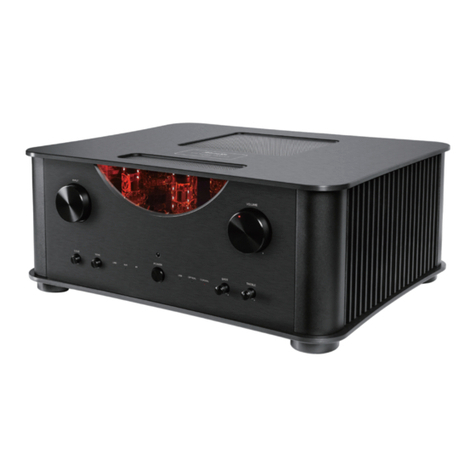
Advanced Visual Solutions AVSP340A User manual

Advanced Visual Solutions Ltd
Unit 2, Eastman Way
Hemel Hempstead, Hertfordshire HP2 7DU
Telephone : ( 01442 ) 252280 Fax : ( 01442 ) 244578
Model
AVSP340A & AVSP480A
340 Watt and 480 Watt
Public Address Mixer
Amplifiers
Installation and Operating
Instructions
Document No. AVSP340-
A
VSP480-OEM01 REVISION 2.1 28
th
October 2008

PUBLIC ADDRESS AMPLIFIER AVSP 340/480 SERIES
_____________________________________________________________________________________________
Contents
Page
Unpacking & Installation............................................... 3
Features ......................................................................... 4
Front Panel Controls..................................................... 5
Rear Panel Controls...................................................... 6
Connecting Audio Signals to the Inputs……………... 10
Installation of the Speaker(s)........................................ 11
Technical Specifications............................................... 13
Illustrations and Diagrams
Front Panel Controls..................................................... 5
Rear Panel Controls & Connections............................ 6
Connecting Audio Sources : Overview & Details…… 9
Loudspeaker Connection Examples............................ 11
Complete Mixer/Amplifier Block Diagram……….…… 12
Document No. AVSP340-AVSP480-OEM03 REVISION 2.1 : 28th October 2008 Page 2 of 13

PUBLIC ADDRESS AMPLIFIER AVSP 340/480 SERIES
_____________________________________________________________________________________________
Unpacking and Installation
Although it is neither complicated to install nor difficult to operate your Public Address Amplifier,
a few minutes of your time is required to read this manual for a properly wired installation and
becoming familiar with its many features and how to use them. Please take a great care in
unpacking your set and do not discard the carton and other packing materials. They may be
needed when moving your set and are required if it ever becomes necessary to return your set
for service.
Never place the unit near radiator, in front of heating vents, to direct sunlight, in excessive
humid or dusty locations to avoid early damage and for years of quality use. Connect your
complementary components as described or illustrated in the following pages.
To prevent fire or shock hazard, do not
Expose the unit to rain or moisture.
** CAUTION **
RISK OF ELECTRIC
SHOCK
DO NOT OPEN
CAUTION TO REDUCE THE RISK OF ELECTRIC
SHOCK DO NOT REMOVE COVER (OR BACK).
NO USER-SERVICEABLE PARTS INSIDE
REFER SERVICING TO QUALIFIED PERSONNEL
This symbol is intended to alert the user to the
presence of uninsulated “dangerous Voltage”
within the product’s enclosure that may be of
sufficient magnitude to constitute a risk of
electric shock to persons.
This symbol is intended to alert the user to the
presence of important operation and
maintenance (servicing) instructions in the
literature accompanying the appliance
Caution: To prevent electric shock do not
use this (polarized) plug with an
extension cord, receptacle or other
outlet unless the blades can be fully
inserted to
p
revent blade ex
p
osure
WARNING
Document No. AVSP340-AVSP480-OEM03 REVISION 2.1 : 28th October 2008 Page 3 of 13

PUBLIC ADDRESS AMPLIFIER AVSP 340/480 SERIES
_____________________________________________________________________________________________
Features
MODULAR AMPLIFIER
This amplifier is perfect for applications requiring high reliability and excellent audio
quality.
Optional modules may be installed in multiple configurations (up to 2 modules). The
option available are AVSP-CDA (CD Player), AVSP-T (AM/FM Radio Tuner) and AVSP-
CT (Cassette Tape Player).
INPUT GAIN & EQ CONTROLS
This system allows adjustment to the input gain & 3-band EQ on the rear panel, which
are all adjustable per channel, for the ultimate convenience.
SPEAKER SELECT
6 speaker selector switches are provided to enable you to select 5 speaker zones
individually or all speaker zones globally. These may be operated by remote-control via
the 15 pin “D” type connector on the rear panel.
SELECTABLE PRIORITY MUTING
Switchable audio signal priority for Channel 1, Channel 2, CHIME and TELEPHONE
inputs over other sources.
5 ZONE DESKTOP MICROPHONE (OPTIONAL)
A desktop microphone is available which plugs directly into the REMOTE connector.
This allows the operator to make an announcement over any or all of the 5 speaker
zones. Contact Advanced Visual Solutions sales department for details.
REMOTE CONTROL SYSTEM
Speaker zones can be selected and the chime function operated by a compatible
remote control system (not available if above microphone is connected).
Document No. AVSP340-AVSP480-OEM03 REVISION 2.1 : 28th October 2008 Page 4 of 13

PUBLIC ADDRESS AMPLIFIER AVSP 340/480 SERIES
_____________________________________________________________________________________________
Front Panel Controls
123
4
5
6
7
9 8
1. CASSETTE DECK, CD PLAYER OR TUNER OPTION
These panels are used for connecting the CD player or TUNER.
*Connection of option is provided by means of a connector inside the unit.
2. PROTECTION INDICATOR
This LED indicates the condition of the protection circuit. When the protection LED is “ON”
the amplifier is not operating normally (overheating and limiting), please check the
INPUT/OUTPUT condition of the amplifier.
3. OUTPUT LEVEL DISPLAY
This display indicates the output level (RMS).
4. POWER SWITCH
Pressing this switch to ON will supply the power to this unit.
The power indicator LED illuminates when the unit is switched on and receiving power.
5. SPEAKER SELECTOR
These switches are used for connecting the output of amplifier to the speaker zones
individually or globally.
6. CHIME BUTTON
Pressing this button will activate the chime circuit.
7. MASTER VOLUME
This control is used for adjusting the overall volume of the mixed audio.
8. TONE CONTROL
High and Low frequency level is adjusted to ±12dB by these 2 controls from 100Hz to 10kHz.
9. Channel 1 ~ Channel 6 VOLUME
These controls adjust the individual volume levels of Channels 1 to 6.
Document No. AVSP340-AVSP480-OEM03 REVISION 2.1 : 28th October 2008 Page 5 of 13

PUBLIC ADDRESS AMPLIFIER AVSP 340/480 SERIES
_____________________________________________________________________________________________
Rear Panel Connections and Controls
EM EXT
CHIME EXT
MUTE
Mains
Inlet
1
8
9
15
REMOTE AMPLIFIER
1
2
3
4
5
9
10
6
7
8
11
12
13
14
15
16
1
7
1. SPEAKER OUTPUT TERMINALS
These terminals are for connection of speaker lines to deliver output to the speaker zones.
These outputs are 100V line outputs, and allow for long-distance loudspeaker cable runs. Be
sure to use only speakers whose combined power rating is equal to or lower than the rated
output power of the amplifier.
PLEASE NOTE : The lower terminals marked COMMON are NOT common to each other,
they are PAIRED. For example, if you wire a speaker to the SP3 (zone 3) output terminal, you
must connect it’s return wire to the COMMON TERMINAL 3 (immediately below the SP3
terminal). The same applies to all the speaker zone output terminals.
2. ANTENNA (AERIAL) : (Only used for Tuner Option Module)
This terminal is for connecting the antenna terminal, when you use the Optional Tuner Module.
3. PHANTOM POWER SWITCH
These switches turn on or off the phantom power supply for each channel.
Use this switch when you are using condenser microphones which require phantom power.
When this switch is on, +22 Volts DC will be supplied to pins 2 and 3 of each INPUT connector.
If you do not need phantom power, (e.g. when using a dynamic microphone), be sure to leave
the switch turned off.
It is safe to connect balanced dynamic microphones or line level devices even if this switch is
left on, but connecting unbalanced devices or devices whose transformers are center-grounded
will cause hum or malfunctions.
4. PRIORITY SWITCH
These switches give priority to the channel to which they belong.
5. H.F. EQUALISER CONTROL
This Eq. section provides ±12dB of control over high frequencies, centered around 10kHz.
6. M.F. EQUALISER CONTROL
This Eq. section provides ±12dB of control over medium frequencies, centered around 1kHz.
7. L.F. EQUALISER CONTROL
This equalizer section provides ±12dB of control over low frequencies, centered around 100 Hz.
Document No. AVSP340-AVSP480-OEM03 REVISION 2.1 : 28th October 2008 Page 6 of 13

PUBLIC ADDRESS AMPLIFIER AVSP 340/480 SERIES
_____________________________________________________________________________________________
8. INPUT GAIN CONTROL
This control should be adjusted according to the input signal source. It should be set so that the
input signal does not exceed input sensitivity. When the input level exceeds the rated sensitivity,
the audio output signal of the amplifier will be distorted and may overload the output stage. Gain
adjustment range of these controls is 44dB, and, as a general guide, the position of these
controls will typically be as follows: -
DYNAMIC MICROPHONE ..................... -50 ~ -60dB
ELECTRET MICROPHONE ................... -30 ~ -50dB
AUX. (FastScan ETC.)............................ …0 ~ -20dB
9. Channel 1 ~ Channel 6 INPUT CONNECTORS (XLR)
These input connections are designed to accept balanced-line signals. Unbalanced devices
may be used by connecting the “cold” terminal to ground. In this case, use this terminal for the
cable screen connection.
10. LINK IN JACK
Allows the expansion of input channels. This jack is provided to accept an input from the output
terminal of an external mixer or other device. Inserting a plug into this connector does not affect
the operation of the system.
11. AMP IN JACK
This jack is for connecting an external signal to the power amplifier input. When a plug is
inserted into this jack, the mixed signal of all the local inputs are disconnected from the power
amplifier, and only the external signal connected to this jack are heard.
12. PREAMP OUT JACK
This jack is for connecting the on-board mixer/preamp output signal to an external device. When
a plug is inserted into this jack, the mixed signal of all the local inputs are disconnected from the
power amplifier. This method of connection is known as an “effects Loop”. The PREAMP OUT
is the “send” path, and the AMP IN is the “Return” path.
13. REMOTE CONTROL INPUT CONNECTOR
This 15 pin, “D” type connector allows remote control of the zone switching and chime
operation. The ZONE control inputs source 700mV DC @ 1mA. Pin functions are as follows: -
PIN 01 : Remote Audio Signal Input HOT (+) PIN 09 : Speaker Remote Control Ground
PIN 02 : Remote Audio Signal Input COLD (-) PIN 10 : +24 Volts DC
PIN 03 : Signal Ground PIN 11 : Chime Trigger
PIN 04 : Speaker Zone 1 Control PIN 12 : No Connection
PIN 05 : Speaker Zone 2 Control PIN 13 : No Connection
PIN 06 : Speaker Zone 3 Control PIN 14 : No Connection
PIN 07 : Speaker Zone 4 Control PIN 15 : No Connection
PIN 08 : Speaker Zone 5 Control SHELL = Ground
The optional 5 zone microphone will plug in here. If this option is used, the remote control
connector cannot be used for any other purpose.
14. MAINS POWER INLET (FIXED CABLE)
15. EXT. MUTE
When these terminals are short-circuited, the signals from Channel 3 to Channel 6, Tuner
module and CD Player module are muted. The signals from Channel 1, Channel 2, LINK IN and
CHIME are not muted. You can use these terminals for remote controlled muting and cascading
amplifiers.
Document No. AVSP340-AVSP480-OEM03 REVISION 2.1 : 28th October 2008 Page 7 of 13

PUBLIC ADDRESS AMPLIFIER AVSP 340/480 SERIES
_____________________________________________________________________________________________
16. EXT. CHIME
When these terminals are short-circuited, the 4-tone chime circuit is activated. You can use
these terminals for remote controlled chiming and cascading amplifiers.
17. EMERGENCY MESSAGE
When the voice store IC option is fitted internally, closing these contacts will broadcast the
stored message.
Document No. AVSP340-AVSP480-OEM03 REVISION 2.1 : 28th October 2008 Page 8 of 13

PUBLIC ADDRESS AMPLIFIER AVSP 340/480 SERIES
_____________________________________________________________________________________________
CONNECTING AUDIO SOURCES TO THE AMPLIFIER
Audio sources generally fall into one of two categories, namely BALANCED and UNBALANCED
(unbalanced sources are sometimes referred to as “single-ended”). Unbalanced sources use
the cable screen (normally Earthed) as one of the conductors and tend to be high impedance
(typically 47K Ohms or more). Balanced types tend to be low impedance (600 Ohms or less).
Electret condenser microphones require a supply Voltage to operate. This is usually provided
from an internal battery, but some can also use power supplied down the cable. This is known
as “PHANTOM POWER” and is available on all inputs (CH1-CH6) of the amplifier.
**CAUTION** When using any source which is not phantom-powered ENSURE THAT THE
PHANTOM SWITCH IS OFF FOR THAT CHANNEL.
CONNECTION TO AN UN-BALANCED SOURCE
An unbalanced (single-ended) audio source may be
connected to any of the input channels. A screened,
single core microphone cable should be used, although it
is permissible to use one core of a twisted pair as long it
has an overall screen. The trim control of the selected
channel should be set to a point where distortion is not
present on the channel.
ENSURE THAT THE CHANNEL’S “PHANTOM” SWITCH
IS IN THE OFF POSITION (OUT).
CONNECTION TO A BALANCED MICROPHONE
A balanced-line microphone may be connected to any of
the input channels. A single-pair or twin-core microphone
cable with overall screen should be used. If the
microphone is an electret condenser type which can
utilise phantom power, set the PHANTOM switch to ON
(In) otherwise set it to OFF.
ENSURE THAT THE CHANNEL’S “PHANTOM” SWITCH
IS IN THE OFF POSITION (OUT) WHEN USING
DYNAMIC TYPE BALANCED MICROPHONES.
CONNECTION TO AN UN-BALANCED MICROPHONE
An unbalanced (single-ended) microphone may be
connected to any of the input channels. A screened,
single core microphone cable should be used, although it
is permissible to use one core of a twisted pair as long it
has an overall screen. The trim control of the selected
channel should be set to a point where distortion is not
present on the channel.
ENSURE THAT THE CHANNEL’S “PHANTOM” SWITCH
IS IN THE OFF POSITION (OUT).
CONNECTION TO ADPRO REMOTE TRANSMITTERS
The Adpro models, FastScan, FastVu and FastTrace all
have unbalanced audio outputs. This drawing shows the
connections for these. A screened, single core
microphone cable should be used, although it is
permissible to use one core of a twisted pair as long it
has an overall screen. The trim control of the selected
channel should be set to minimum.
ENSURE THAT THE CHANNEL’S “PHANTOM” SWITCH
IS IN THE OFF POSITION (OUT).
Document No. AVSP340-AVSP480-OEM03 REVISION 2.1 : 28th October 2008 Page 9 of 13

PUBLIC ADDRESS AMPLIFIER AVSP 340/480 SERIES
_____________________________________________________________________________________________
CONNECTING TO ADPRO FastScan, FastVu or FastTrace TRANSMITTERS.
ENSURE THAT THE CHANNEL’S “PHANTOM” SWITCH IS IN THE OFF POSITION (OUT).
If any ADPRO transmitter is connected to the amplifier’s input while the “Phantom” switch is set
to the ON position, the transmitter may suffer permanent damage or fail to operate correctly.
The audio output from the ADPRO transmitter should be taken from the 15 pin “D” type
connector marked “AUXILIARY I/O”, in the case of a FastScan transmitter, or “SWITCHER” in
case of a FastVu or FastTrace transmitter.
You MUST use a screened microphone type cable, connecting it to the XLR input connector as
shown in the diagram on the previous page.
The signal should be connected into INPUT 1 of the amplifier, and the “INPUT TRIM” control,
shown on the rear panel control drawing on page 6, should be set to minimum (fully anti-
clockwise).
Set the EQ controls for this channel as follows:-
“HIGH” Set to mid-way
“MID Set to mid-way
“LOW” Set fully anti-clockwise
The remaining inputs may be used for other audio sources (e.g. local microphones, Paging
systems etc).
Document No. AVSP340-AVSP480-OEM03 REVISION 2.1 : 28th October 2008 Page 10 of 13

PUBLIC ADDRESS AMPLIFIER AVSP 340/480 SERIES
_____________________________________________________________________________________________
Example 2
Installation of the Loudspeakers
There is no low-impedance output from these amplifiers. All speakers should be of the 100 Volt
Line type.
When you connect the loudspeakers, remove the power cord from the Mains AC outlet.
Connect loudspeakers in parallel (either star or daisy-chain). You can continue to connect high-
impedance speakers (100 Volt Line types) in parallel until the total power rating of all the
speakers added together equal the power rating of the amplifier. Two examples are shown
below.
Example 1
30W 60W 20W
40W
30W
Speaker Terminals
In this example, the total power demand of the speakers, when all speaker zones are selected,
is 180 Watts (30+30+60+40+20). This would require an amplifier capable of delivering at least
180 Watts RMS power. In this case the AVSP340A would deliver the required power and leave
160 Watts spare capacity.
90W 80W 30W
In this example, the total power demand of the speakers, when all speaker zones are selected,
this case the AVSP340A would deliver the required power and leave
50 Watts spare capacity.
Speaker Terminals
90W
is 290 Watts (90+90+80+30). This would require an amplifier capable of delivering at least
290 Watts RMS power. In
Document No. AVSP340-AVSP480-OEM03 REVISION 2.1 : 28th October 2008 Page 11 of 13

PUBLIC ADDRESS AMPLIFIER AVSP 340/480 SERIES
_____________________________________________________________________________________________
AVSP360A / AVSP480A BLOCK DIAGRAM
Document No. AVSP340-AVSP480-OEM03 REVISION 2.1 : 28th October 2008 Page 12 of 13

PUBLIC ADDRESS AMPLIFIER AVSP 340/480 SERIES
_____________________________________________________________________________________________
TECHNICAL SPECIFICATIONS
Rated Output Power (THD 1%) AVSP120A : 120W (RMS)
AVSP340A : 340W
(RMS)
AVSP480A : 480W (RMS)
Frequency Response (Amp In) 80Hz—20KHz
T.H.D (at 1 kHz Half Power Output) Less than 1%
S/N Ratio Better than 88dB
Input Sensitivity/Impedance
CH1 ~ CH6 1 mV~160mV/600Ω
Link In 100mV/10kΩ
Amp In 1V/20kΩ
Remote In 1V 10KΩ
Pre Amp Voltage Output / Impedance 1V @ 600Ω
Global Tone Control (100Hz, 10KHz centres) ±12dB
Channel E.Q. Control (100Hz, 1KHz, 10KHz centres) ±12dB
Speaker Voltage Output / Impedance
AVSP120A (120 Watt) 4Ω120W
70V = 42Ω
100V = 83Ω
AVSP340A (340 Watt) 100V = 29.4Ω
AVSP480A (480 Watt) 100V = 20.8Ω
Power Source AC 110V / 240V, 50/60 Hz
Power Consumption AVSP120A : 300W @ Full Output Power
AVSP340A : 620W @ Full Output Power
AVSP480A : 880W @ Full Output Power
Weight
AVSP120A : 13.0kg (28.7lb)
AVSP340A : 13.5kg (29.7lb)
AVSP480A : 15.5kg (34.2lb)
Dimensions 420(W) x 132(H) x 360(D)mm
Operating Temperature 14oF ~ 104oF ( -10oC ~ +40oC)
** Specifications and design subject to change without notice for improvements **
Document No. AVSP340-AVSP480-OEM03 REVISION 2.1 : 28th October 2008 Page 13 of 13
This manual suits for next models
1
Table of contents
Other Advanced Visual Solutions Amplifier manuals
